Advertisement
Installer's Guide
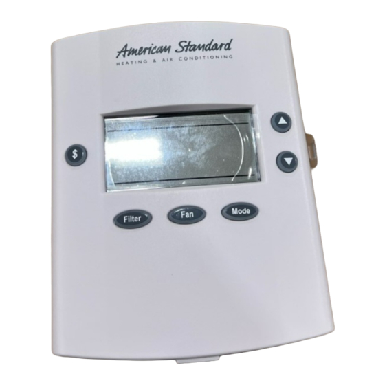
ACONT200AN11AA
1 Heat (Gas, Oil* or Elec) / 1 Cool
Electronic Non-Programmable, 4 Wire Hookup
ALL phases of this installation must comply with NATIONAL, STATE AND LOCAL CODES
Note: Read the entire instruction manual before starting the
installation.
Contents
Introduction ........................................................................ 1
Application .......................................................................... 1
Product Specifications ...................................................... 1
Installation .......................................................................... 2
Mounting and Wiring .......................................................... 2
SETUP ................................................................................. 4
Checkout ............................................................................. 4
Troubleshooting .................................................................. 6
Features .............................................................................. 7
▲
!
To prevent shortening its service life, the control should not
be installed until construction is completed.
Introduction
ACONT200AN11AA is a digital non-programmable 1Heat/1
Cool wall mounted low voltage (24Vac) Comfort Control with
backlit LCD and keypad. It maintains room temperature by
controlling the operation of heating and cooling systems. The
Comfort Control is easily configured for Heating Only (gas or
electric) or Cooling Only applications via the user friendly
Installer Setup menu. The Comfort Control features separate
heating and cooling setpoints, selectable Auto or Manual
Changeover, adjustable Energy Saving mode, adjustable
filter reminder and LitePort technology for extended system
diagnostics and fault notification. Setup selections and
diagnostics are stored indefinitely in the Comfort Controls
nonvolatile memory eliminating the need for battery backup.
Safety Considerations
Read the following manufacturer instructions carefully.
Follow all local codes during installation. All wiring must
conform to local and national electrical codes. Improper
wiring or installation may damage comfort control.
Recognize safety information. This is the safety alert symbol
▲
!
. When you see this symbol on the equipment and in the
instruction manual, be alert to the potential for personal
injury.
Understand the signal words DANGER, WARNING and
CAUTION. These words are used with the safety-alert
symbol. DANGER indentifies the most serious hazards which
will result in severe personal injury or death. WARNING
signifies a hazard which could result in personal injury or
death. CAUTION is used to identify unsafe practices which
could result in minor personal injury or product and prop-
erty damage.
© 2008 American Standard Heating & Air Conditioning
CAUTION
$
Application Hook-up diagrams
1 Heat / 1 Cool (Gas or Electric)
1 Heat / 0 Cool (Gas or Electric)
0 Heat / 1 Cool
1 Heat / 1 Cool (Oil Furnace)
1 Heat / 0 Cool (Oil Furnace)
SYSTEM MODE: HEAT, COOL, AUTO and OFF
FAN MODE: AUTO or ON
* Requires external relay for Oil furnace applications.
Product Specifications
- Power Source: /20V-30VAC, 50/60Hz, Load Powered
through W and Y.
- Cooling setpoint temperature range: 65F - 90F,
18.0C - 33.0C, 1F and 0.5C resolution.
- Heating setpoint temperature range: 40F- 85F,
5.0C - 30.0C, 1F and 0.5C resolution.
- Default set points: 68F, 20.0C Heat, 78F, 25.5C Cool
- Storage Range: -40F to 140F, 5% - 90% RH non-
condensing.
- Operating Temperature range: 32F - 110F, 5 - 90% RH
non-condensing.
- Minimum Cycle Off Time Delay: Cooling - 5 minutes,
Heating - 1 minute.
- Use minimum 18 gauge NEC approved control
wiring.
11-HD03D1-3
Available in French Canadian (FC)
FILTER
FAN
MODE
FIG
Fig. 3, 4, & 5
Fig. 6
Fig. 5
Fig. 7
Fig. 8
Advertisement
Table of Contents

Related Manuals for American Standard ACONT200AN11AA


Summary of Contents for American Standard ACONT200AN11AA
-
Page 1: Product Specifications
CAUTION is used to identify unsafe practices which Heating - 1 minute. could result in minor personal injury or product and prop- - Use minimum 18 gauge NEC approved control erty damage. wiring. © 2008 American Standard Heating & Air Conditioning... -
Page 2: Installation
Installer’s Guide Fold Business card & insert My Company Installation into slot A/C & Heating Location Service The Comfort Control should be mounted approximately 60” (1.5m) off the floor on an interior partition wall. Never install (123) 456-7890 the Home Comfort Control on an outside wall. For proper temperature sensing, avoid mounting the Comfort Control where it will be exposed to heat radiated from lamps, sun light, fireplaces or any other radiant heat sources. -
Page 3: Hd03D1
Installer’s Guide Figure 3 SINGLE STAGE FURNACE / SINGLE STAGE COOLING Figure 7 SINGLE STAGE OIL FURNACE / SINGLE STAGE COOLING COMFORT CONTROL SINGLE STAGE SINGLE STAGE COMFORT CONTROL TERMINAL BLOCK GAS FURNACE OIL FURNACE TERMINAL BLOCK 24VAC HOT 24VAC HOT SINGLE STAGE SINGLE STAGE AIR CONDITIONER... -
Page 4: Setup
Installer’s Guide SETUP Checkout There are two methods of verifying that the Comfort Control Enter INSTALLER Setup: operates the system as intended. (See Table 2, steps 1-50 for option details) Method 1: Normal Mode 1.) Set System Mode to OFF This can be accomplished by pressing the appropriate keypad button(s) to cycle the system through each of the 2.) Set Fan to AUTO... - Page 5 Installer’s Guide Control Setup Ta b le 2 IN S TA L L E R S E T U P (IS U ) U S E R S E T U P (U S U ) 1 . S e t S y s te m M O D E to O F F 2 .
-
Page 6: Troubleshooting
Installer’s Guide Troubleshooting Table 3 Troubleshooting Symptom Possible Cause Action 1. Blown fuse or tripped circuit breaker. 1. Replace fuse or reset breaker. 2. Furnace power switch OFF. 2. Turn switch to ON. Display will not come on. 3. Furnace blower compartment door or panel 3. -
Page 7: Features
Installer’s Guide Keypad Lock Features Locking the control’s keypad can help prevent unwanted Cycle Rate tampering or changing the thermostat settings by pressing The selected number of system cycles per hour. If the cycle the controls UP and DOWN arrow keypad buttons at the rate were set to 3, each cycle would be 20 minutes long. - Page 8 Notes Since American Standard Heating & Air Conditioning has a policy of continuous product and product data improvement, it reserves the right to change specifications and design without notice. Technical Literature - Printed in U.S.A. American Standard Heating & Air Conditioning...
Need help?
Do you have a question about the ACONT200AN11AA and is the answer not in the manual?
Questions and answers