
Related Manuals for Skywalker X8


Summary of Contents for Skywalker X8
- Page 1 Skywalker X8 Assembly manual January 2013 This Manual Was Created by Ray Grauberger www.raygrauberger.com ...
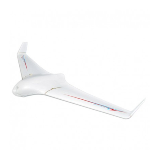
- Page 2 Technical Data This is the X-8 FPV wing from Skywalker Technology. The BIG FPV wing! The X-8 has been specifically designed for FPV and UAV, customized for F-Tek stabilizer systems. An awesome looking and fantastic flying FPV / UAV platform, molded out of EPO so it's nearly...
- Page 3 CENTER OF GRAVITY The position of the center of gravity for the Skywalker X8 is 440 millimeters away from the nose, a 5 millimeter correction either forward or backwards from this point may be needed. The design of the Skywalker X8 puts the Center of Gravity point and the rear edge of the hand hold slots on the bottom of the model, so measuring is not needed.
- Page 4 PARTS LIST QUANTITY DESCRIPTION 1 2 Part EPO (expanded polyolefin) Split Fuselage 1 EPO Fuselage Hatch 2 EPO Main Wings 2 EPO Main Wing Access Panels 2 EPO Winglets 1 590.55 millimeter Front Carbon Fiber Wing Tube 1 889 millimeter Rear Carbon Fiber Wing Tube 1 Wooden Oval Motor Mount 4 ...
- Page 5 ...
- Page 6 Skywalker X8 Assembly Procedure 1. Glue the winglet butt‐plate to the winglet PHOTOS 1A, 1B, 1C, 1D 2. Glue the magnetic hold down structures together PHOTOS 2A, 2B 3. Glue the magnetic hold down structures into the wing body PHOTOS 3A, 3B, 3C 4. Gluing the rudder horns PHOTOS 4A, 4B 5. Trial fitting the servo and elevon configuration 6. Advanced wing configuration using Drag Rudders (see Appendix A) 7. Gluing the servos in place PHOTOS 7A, 7B ...
- Page 7 Assembly Instructions Glue the winglet butt‐plate to the winglet Spread the supplied glue evenly over the winglet bottom. Also spread the supplied glue on one side of the wooden butt‐plate, (make sure this is NOT the butt‐plate marked with a “T”). Wait approximately 5 minutes for the glue to dry until it is no longer sticky. Do this for both pieces before pressing them together, this will allow you to better align the winglet and the butt‐plate. See Photos: 1A, 1B, 1C, and 1D. PHOTO 1A PHOTO 1B ...
- Page 8 PHOTO 1C PHOTO 1D Glue the magnets and the hold down structure together Assemble the hatch magnets into the magnet holders by forcing them into the precut holes in the wooden magnet holders. Make sure you have 4 North and 4 South Pole sets, mark the holders in a way that you don’t mix them up. Doing this incorrectly will reverse the magnetic force, the wrong magnetic direction could cause an unwanted failure or hatch loss in flight. After you have forced the magnets into place, use Cyanoacrylate or ...
- Page 9 (CA) to affix the magnets permanently in the wooden magnet holders. Just a drop will be plenty to hold the magnets. See Photos 2A and 2B. PHOTO 2A PHOTO 2B 3. Glue the magnetic hold down structure into the wing body Using the supplied glue apply liberally to the magnetic hold downs, allow the glue to dry for approximately 5 minutes. Apply glue to the wings hatch and fuselage wait approximately 5 minutes for the glue to dry. After the glue has dried, paying close attention to the North and South poles of the magnets insert them into the wing ...
- Page 10 and fuselage. If you previously marked the North and South poles of your magnet hold downs as mentioned in Step 2, this assembly procedure will go much easier. After the glue has set in both the fuselage and hatch put the two pieces together and inspect the fit, make any adjustments at this time to insure there is a solid fit between the hatch and the wing. Pay careful attention to the spacing between the two hold down parts and the wing and hatch. See Photos 3A, 3B, and 3C. PHOTO 3A PHOTO 3B ...
- Page 11 PHOTO 3C 4. Gluing the Rudder Horns Spread just enough glue onto the wings control surface to accept the rudder control horn. Make sure you spread the glue evenly and allow it to dry. Do the same for the control horn itself. After both the control surface and control horn have dried, insert the control horn into the pre‐marked holes in the control surface. See Photos 4A and 4B. PHOTO 4A ...
- Page 12 PHOTO 4B 5. Trial fitting the servo and elevon configuration This is the standard radio set‐up for the Skywalker X8. At this point you should have your radio setup for a delta wing, elevon configuration. If you have not set‐up your radio yet, do this now before continuing. With all of your electronics turned on let the servos self‐center themselves. Turn off your electronics and attach the servo horns to your servos at a right angle to the longest surface of the servo. 6. Advanced Wing Configuration using Drag Rudders There is a more advanced flying configuration that requires control surface and wing modification with advanced radio set‐up discussed later in this document. See Appendix A. Gluing the servos in place Use a standard size servo or a servo that has more than 2.5 KG of force for the Skywalker X8. Plug in the servo extension cable supplied with the kit. Apply glue to one side of the servo and also apply glue to the servo cut‐ out in the wings. Wait for the glue to dry (approximately 5 minutes) then place the servo into the wing. Place the servo extension wire into the preformed channel in the wing. See Photos 7A and 7B. ...
- Page 13 PHOTO 7A PHOTO 7B ...
- Page 14 8. Mounting the Pushrod and Pushrod Connector Insert the pushrod into the uppermost hole in the servo arm. Slide the pushrod connector onto the pushrod and attach the pushrod connector with one of the supplied black screws. Cut off any excess length off the pushrod. The pushrod should not extend more than 1/8” of an inch past the pushrod connector. See Photo 8A. PHOTO 8A 9. Gluing the Main Wing Winglet Butt‐Plate Liberally apply a smooth layer of glue to the winglet butt‐plate these butt‐plates are marked with a “T”. Apply a smooth layer of glue to the main wing as well. Allow the glue to dry on both the wing and butt‐plate (about 5 minutes), then press them together aligning them accurately. See Photos 9A and 9B. PHOTO 9A...
- Page 15 PHOTO 9B 10. Separating the Control surface from the Wing Use a new or extremely sharp blade to cut the control surface sides from the wing. You will NOT be removing the control surface completely, just allowing it to move up and down with the longest side uncut. It is recommended to leave a 1.5 millimeter gap between the wing and the control surface. See Photo 10A. PHOTO 10A ...
- Page 16 11. Wing Plate Bonding with Servo Extension Installation If you are using drag rudders, do NOT do this step until you have read and completed Appendix A. Spread glue onto the recess in the wing where the wing plate will sit. Make sure you do NOT cover the Wing Tube area with glue. Carefully insert the servo extension into the wing panel cut‐out channel, make sure that the servo wire is firmly in place and the extension is tight from the servo. Spread glue evenly onto the wing plate allowing the wing glue and wing plate to dry (about 5 minutes). Carefully compress the wing panel to the wing adjusting for fit. Try to make sure that the butt end of the wing plate is even with the end of the wing. See Photos 11A, 11B, 11C and 11D. PHOTO 11A PHOTO 11B ...
- Page 17 PHOTO 11C PHOTO 11D 12. Adding the Wing Butt‐Plate to the Main Wing Apply the supplied glue to the inner wing edge, make sure not to get any glue into the wing tube hole. Also apply glue to the butt‐plate, allow the glue to dry on both pieces for about 5 minutes. After the glue has dried insert the wing tube into it the wing tube cavity to help align the butt‐plate for the most accurate fit. Next insert the wing tube into the wing tube hole in the butt‐plate, and attach the butt‐plate to the wing. ...
- Page 18 See Photos 12A, 12B, 12C, and 12D. PHOTO 12A PHOTO 12B ...
- Page 19 PHOTO 12C PHOTO 12D ...
- Page 20 13. Running the Servo Extension into the Main Fuselage Body You will need to widen the slot in the fuselage so that the plug end of the servo lead will fit through the hole after the fuselage has been glued together. See Photos 13A and 13B. PHOTO 13A PHOTO 13B 14. Installing the Motor Mount into the Fuselage Optionally you can attach your motor to the motor mount before gluing it into the fuselage. If you do not attach your motor at this time you should have no problems mounting the motor after further construction. See Photos 14A, 14B, 14C, and 14D ...
- Page 21 PHOTO 14A PHOTO 14B. ...
- Page 22 PHOTO 14C PHOTO 14D ...
- Page 23 15. Gluing the Fuselage Halves Apply glue to the top and bottom sections of your fuselage. Wait approximately 5 minutes for the glue to dry. After the glue has dried press the two halves together forming a tight bond between the two halves together. Make sure to avoid the wing tube cut‐out area. See Photos 15A, 15B, 15C, and 15D. PHOTO 15A PHOTO 15B ...
- Page 24 PHOTO 15C PHOTO 15D 16. Installing the Wing Butt‐Plate onto the Fuselage Apply the supplied glue to the inner fuselage wing edge, make sure not to get any glue into the wing tube hole. Also apply glue to the butt‐plate, allow the glue to dry on both pieces for about 5 minutes. After the glue has dried insert the wing tube into it the fuselage wing tube cavity to help align the butt‐plate for the most accurate fit. Next attach the butt‐plate to the fuselage. See Photos 16A, 16B, and 16C. ...
- Page 25 PHOTO 16A PHOTO 16B ...
- Page 26 PHOTO 16C 17. Winglet Final Assembly Attach the winglet to the main wing with the two supplied 3x8 screws. If you plan on removing the winglets and re‐attaching prior to transport and flying you should add some foam safe CA to the winglet screw holes. By adding CA to the screw holes you are hardening the wood to accept the screws for multiple attachment and detachment of the winglet. See Photo 17A PHOTO 17A ...
- Page 27 18. Attaching the Motor If you did not pre‐attach the motor in step 15, you should attach the motor now. Follow the directions from the manufacturer of your motor to mount it. If your motor is not centered using the pre drilled holes in the motor mount, you should drill new holes to attach your motor, trying to keep the shaft as centered as possible in the center of the rear fuselage hole. See Photos 18A and 18B. PHOTO 18A PHOTO 18B ...
- Page 28 19. Recessed Camera Mount There are a multitude of fixed board cameras that will mount in the front of your Skywalker X8 without modification. There is also a pre‐formed hole in the fuselage to run your camera wires through. Also with the wide fuselage you have plenty of room to separate your video and audio transmitter from you radios receiver. If you are using a GOPRO camera for you FPV implementation you will need to make some modifications to the fuselage. First you will need to cut out a round hole to accommodate the GOPRO’s round lens, also beveling the surface so that you are not obscuring the wide‐angle lens. See Photos 19A, 19B, and 19C. PHOTO 19A PHOTO 19B ...
- Page 29 PHOTO 19C 20. The Skywalker X8 Final Assembly Your final assembly should look almost identical to what you see in the photo. See Photos 20A, 20B, and 20C. PHOTO 20A ...
- Page 30 PHOTO 20B PHOTO 20C ...
- Page 31 21. Skywalker X8 Center of Gravity The center of gravity is marked by the rear most part of the cutouts for hand launching. This position is 440 millimeters away from the front of the fuselage. You may have to adjust the CG approximately either 5 millimeters forward or backwards from this starting point. See Photo 21A. PHOTO 21A 22. Assembly and Disassembly for Transportation Here the Skywalker X8 is shown partially disassembled for transportation or storage. See Photos 22A, 22B, 22C, 22D, and 22E. PHOTO 22A ...
- Page 32 PHOTO 22B PHOTO 22C ...
- Page 33 PHOTO 22D PHOTO 22E ...
- Page 34 23. Finished Skywalker X8 At this point the assembly of the Skywalker X8 should be complete. The last part of your assembly should be you radios receiver and you FPV equipment. See Photo 23A. PHOTO 23A ...
- Page 35 APPENDIX A READ THIS COMPLETELY BEFORE CONTINUING ON TO THIS CONFIGURATION CONVERTING STANDARD ELEVON TO DRAG RUDDER CONFIGURATION To convert the Skywalker X8 to a drag rudder configuration, you will need the following additional parts. Quantity Description 2 Control horns 2 Control rods 2 Pushrod connectors 2 Servos with a minimum of 2.5 Kg of force 2 Servo extensions 1. Measure the control surface, divide the control surface into two equal parts marking the location. 2. Cut the control surface into two equal parts, leaving about a 1.5 millimeter gap between the now two control surfaces so that they move independently of each other. ...
Need help?
Do you have a question about the X8 and is the answer not in the manual?
Questions and answers