Advertisement
Table of Contents
- 1 Table of Contents
- 2 Warning Decal Placement
- 3 Important Precautions
- 4 Before You Begin
- 5 Part Identification Chart
- 6 Assembly
- 7 How to Use the Elliptical
- 8 Fcc Information
- 9 Maintenance and Troubleshooting
- 10 Exercise Guidelines
- 11 Part List
- 12 Exploded Drawing
- 13 Ordering Replacement Parts
- 14 Limited Warranty
- Download this manual
www.nordictrack.com
Model No. 831.23900.0
Serial No.
Write the serial number in the space
above for reference.
Serial
Number
Decal
ACTIVATE YOUR
WARRANTY
To register your product and
activate your warranty today, go
to www.nordictrackservice.com/
registration.
CUSTOMER CARE
For service at any time, go to
www.nordictrackservice.com.
Or call 1-800-TO-BE-FIT
(1-800-862-3348)
Mon.–Fri. 6 a.m.–6 p.m. MT
Sat. 8 a.m.–12 p.m. MT
Please do not contact the store.
CAUTION
Read all precautions and instruc-
tions in this manual before using
this equipment. Keep this manual
for future reference.
USER'S MANUAL
Advertisement
Table of Contents

Related Manuals for NordicTrack A.C.T. Elite


Summary of Contents for NordicTrack A.C.T. Elite
- Page 1 USER’S MANUAL Model No. 831.23900.0 Serial No. Write the serial number in the space above for reference. Serial Number Decal ACTIVATE YOUR WARRANTY To register your product and activate your warranty today, go to www.nordictrackservice.com/ registration. CUSTOMER CARE For service at any time, go to www.nordictrackservice.com.
-
Page 2: Table Of Contents
® Bluetooth SIG, Inc. and are used under license. Google Maps is a trademark of Google Inc. IFIT is a registered trademark of ICON Health & Fitness, Inc NORDICTRACK is a registered trademark of ICON Health & Fitness, Inc. -
Page 3: Important Precautions
IMPORTANT PRECAUTIONS WARNING: To reduce the risk of serious injury, read all important precautions and instructions in this manual and all warnings on your elliptical before using your elliptical. ICON assumes no responsibility for personal injury or property damage sustained by or through the use of this product. - Page 5 STANDARD SERVICE PLANS...
-
Page 6: Before You Begin
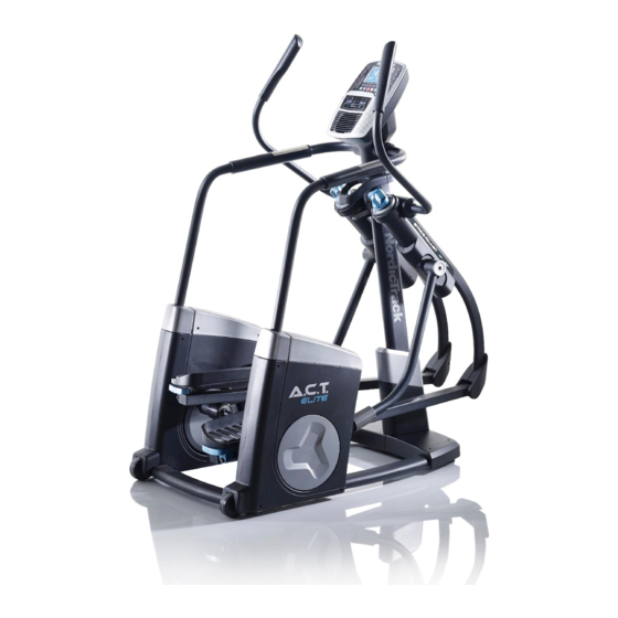
BEFORE YOU BEGIN Thank you for selecting the revolutionary reading this manual, please see the front cover of this NORDICTRACK ACT ELITE elliptical. The ACT ELITE manual. To help us assist you, note the product model ® elliptical provides an impressive selection of features number and serial number before contacting us. -
Page 7: Part Identification Chart
PART IDENTIFICATION CHART Use the drawings below to identify the small parts needed for assembly. The number in parentheses below each drawing is the key number of the part, from the PART LIST near the end of this manual. The number following the key number is the quantity needed for assembly. -
Page 8: Assembly
ASSEMBLY • Assembly requires two persons. • In addition to the included tool(s), assembly requires the following tools: • Place all parts in a cleared area and remove the one Phillips screwdriver packing materials. Do not dispose of the packing materials until you fi... - Page 9 3. Have a second person lift the Right Pedal (9) and the Right Pedal Arm (15). Using a plastic bag to keep your fingers clean, apply some of the included grease to the right Link Arm Bracket (43) in the location shown. Tip: Avoid pinching your fingers.
- Page 10 5. Attach the lower end of the Right Handrail (5) to the Frame (1) with four M8 x 20mm Screws (61); do not tighten the Screws yet. Attach the lower end of the Left Handrail (4) in the same way. See step 2.
- Page 11 7. Align the plastic post inside the Right Handrail Cover (7) with the indicated hole in the Right Shield Cover (76). Press the Right Handrail Cover (7) onto the Right Shield Cover (76) and onto the Right Outer Post and Inner Shields (17, 19). Attach the Right Handrail Cover (7) with an M4 x Hole 16mm Screw (67).
- Page 12 9. Have a second person hold the Console (3) near the Upright (2). Avoid pinching Plug the Upper Wire (81) into the large recepta- the wires cle on the back of the Console (3). Next, plug the Right and Left Pulse Wires (80, 85) into the right and left receptacles.
- Page 13 11. Identify the Right Handlebar (11). Attach the Right Handlebar (11) to the Right Handlebar Arm (13) with three M8 x 25mm Flat Head Screws (68). Attach the Left Handlebar (10) in the same way. 12. Attach the right Handlebar Cover (31) to the Right Handlebar (11) with three M4 x 16mm Screws (67).
- Page 14 13. Plug the Power Adapter (84) into the receptacle on the frame of the elliptical. Note: To plug the Power Adapter (84) into an outlet, see HOW TO PLUG IN THE POWER ADAPTER on page 15. 14. Make sure that all parts are properly tightened before you use the elliptical. Note: Extra parts may be included.
-
Page 15: How To Use The Elliptical
HOW TO USE THE ELLIPTICAL HOW TO PLUG IN THE POWER ADAPTER HOW TO LEVEL THE ELLIPTICAL IMPORTANT: If the elliptical has been exposed to If the elliptical rocks cold temperatures, allow it to warm to room tem- slightly on your perature before you plug in the power adapter. - Page 16 HOW TO ADJUST THE POSITIONS OF THE HOW TO EXERCISE ON THE ELLIPTICAL PEDALS To mount the elliptical, hold the handlebars and step Each pedal can be adjusted to several positions. onto the pedal that is in the lower position. Then, step To adjust each pedal, simply pull the pedal handle onto the other pedal.
- Page 17 CONSOLE DIAGRAM MAKE YOUR FITNESS GOALS A REALITY WITH Upload your workout results to the iFit cloud IFIT.COM and track your accomplishments. With your new iFit-compatible fitness equipment, you can use an array of features on iFit.com to make your Set calorie, time, or distance goals for your fitness goals a reality: workouts.
- Page 18 FEATURES OF THE CONSOLE HOW TO USE THE MANUAL MODE The advanced console offers an array of features 1. Begin pedaling or press any button on the designed to make your workouts more effective and console to turn on the console. enjoyable.
- Page 19 Distance—This display will show the distance that heart rate monitor (see page 23 for infor- mation about the optional chest heart rate you have pedaled in miles (mi) or kilometers (km). monitor). Note: The console is compatible with Pulse (BPM)—This display will show your heart BLUETOOTH Smart heart rate monitors.
- Page 20 HOW TO USE AN ONBOARD WORKOUT speed will appear in the display for a few seconds to alert you. The resistance of the pedals will then 1. Begin pedaling or press any button on the change. console to turn on the console. As you exercise, keep your pedaling speed near When you turn on the console, the display will turn the target speed for the current segment.
- Page 21 HOW TO USE A SET-A-GOAL WORKOUT Note: The calorie goal is an estimate of the number of calories that you will burn during 1. Begin pedaling or press any button on the the workout. The actual number of calories that console to turn on the console.
- Page 22 HOW TO USE AN IFIT WORKOUT and decrease buttons to select the desired work- out. Then, press the Enter button to start the You must have an iFit module to use an iFit workout. workout. To purchase an iFit module at any time, go to www.iFit.com or call the telephone number on the For more information on the iFit workouts, front cover of this manual.
- Page 23 HOW TO USE THE SOUND SYSTEM THE OPTIONAL CHEST HEART RATE MONITOR To play music or audio books through the console Whether your sound system while you exercise, plug a 3.5 mm male goal is to to 3.5 mm male audio cable (not included) into the jack burn fat or to on the console and into a jack on your MP3 player, strengthen your...
- Page 24 HOW TO CHANGE CONSOLE SETTINGS To view distance in miles, select ENGLISH. To view distance in kilometers, select METRIC. 1. Select the settings mode. Demo—The console features a display demo To select the settings mode, press the Settings mode, designed to be used if the elliptical is dis- button.
-
Page 25: Fcc Information
FCC INFORMATION This equipment has been tested and found to comply with the limits for a Class B digital device, pursuant to part 15 of the FCC Rules. These limits are designed to provide reasonable protection against harmful interference in a residential installation. This equipment generates, uses, and can radiate radio frequency energy and, if not installed and used in accordance with the instructions, may cause harmful interference to radio communications. -
Page 26: Maintenance And Troubleshooting
MAINTENANCE AND TROUBLESHOOTING MAINTENANCE Using a standard (flat) screwdriver, carefully pry off the Left Shield Disc (103). Inspect and tighten all parts of the elliptical regularly. Replace any worn parts immediately. To clean the elliptical, use a damp cloth and a small amount of mild soap. - Page 27 HOW TO ADJUST THE DRIVE BELT Next, loosen the Pivot Screw (97), tighten the Belt Adjustment Screw (79) until the Drive Belt (57) is tight, If the pedals slip while you are pedaling, even while and then retighten the Pivot Screw. the resistance is adjusted to the highest level, the drive belt may need to be adjusted.
-
Page 28: Exercise Guidelines
EXERCISE GUIDELINES Burning Fat—To burn fat effectively, you must exer- WARNING: cise at a low intensity level for a sustained period of Before beginning this time. During the first few minutes of exercise, your or any exercise program, consult your physi- body uses carbohydrate calories for energy. - Page 29 SUGGESTED STRETCHES The correct form for several basic stretches is shown at the right. Move slowly as you stretch; never bounce. 1. Toe Touch Stretch Stand with your knees bent slightly and slowly bend forward from your hips. Allow your back and shoulders to relax as you reach down toward your toes as far as possible.
- Page 30 NOTES...
-
Page 31: Part List
PART LIST Model No. 831.23900.0 R0814A Key No. Qty. Description Key No. Qty. Description Frame Wheel Upright Leveling Foot Console Pulley Left Handrail Right Frame Cover Right Handrail Eddy Mechanism Left Handrail Cover Left Frame Cover Right Handrail Cover Drive Belt Link Arm M8 Jam Nut Right Pedal... - Page 32 Key No. Qty. Description Key No. Qty. Description M10 Split Washer Link Arm Spacer Left Shield Cover Sliding Block Left Shield Disc End Block Assembly Left Shield Insert Pedal Arm Axle M10 Locknut M6 x 36mm Bolt M4 x 19mm Screw Adjustment Assembly Right Pedal Handle M8 x 45mm Bolt...
-
Page 33: Exploded Drawing
EXPLODED DRAWING A Model No. 831.23900.0 R0814A... - Page 34 EXPLODED DRAWING B Model No. 831.23900.0 R0814A...
- Page 35 EXPLODED DRAWING C Model No. 831.23900.0 R0814A...
-
Page 36: Ordering Replacement Parts
ORDERING REPLACEMENT PARTS To order replacement parts, please see the front cover of this manual. To help us assist you, be prepared to provide the following information when contacting us: • the model number and serial number of the product (see the front cover of this manual) •...
Need help?
Do you have a question about the A.C.T. Elite and is the answer not in the manual?
Questions and answers
Is monitor battery or electric