Table of Contents
Advertisement
Advertisement
Chapters
Table of Contents
Troubleshooting

Related Manuals for Tennant 215


Summary of Contents for Tennant 215
- Page 1 Operator and Parts Manual (Operator Manual) MM157...
- Page 2 CALIFORNIA PROPOSITION 65 WARNING: Engine exhaust from this product contains chemicals known to the State of California to cause cancer, birth defects, or other reproductive harm. Copyright E 1986, 1987, 1988, 1989, 1990, 1991, 1993, 1994, 1998 TENNANT, Printed in U.S.A.
-
Page 3: General Information
- - Use Cardboard To Locate Leaking Unless Designed For Use In Those Hydraulic Fluid Under Pressure. Areas. - - Use TENNANT Supplied Or Equivalent - - In Areas With Possible Falling Objects Replacement Parts. Unless Equipped With Overhead Guard. - Page 4 HOPPER WARNING LABEL - - LOCATED ON THE HOPPER SIDE OF THE FRONT SUPPORT PARTITION. HOPPER SUPPORT BAR WARNING LABEL FOR SAFETY LABEL - - LOCATED ON THE - - LOCATED ON THE OPERATOR SIDE OF SEAT SHROUD. THE HOPPER. 215 MM157 (6- -96)
- Page 5 ....1--3 GENERAL MACHINE PERFORMANCE 1--3 MACHINE DIMENSIONS ....1--4 215 MM157 (6- -88)
- Page 6 SPECIFICATIONS 215 MM157 (6- -88)
-
Page 7: Machine Specifications 1
Cylinder (LPG) --- single action type, 2 in (50 Maximum reverse speed -- 2 mph (3 km/h) mm) bore x 5.7 in (145 mm) stroke, 1 in (25 Turning radius -- 67 in (1700 mm) mm) diameter rod,2500 psi (17,240 kPa) maximum rated pressure. 215 MM157 (6- -88) -
Page 8: Machine Dimensions 1
SPECIFICATIONS MACHINE DIMENSIONS 63.75 in (1620 mm) 46.75 in (1190 mm) TOP VIEW 53.75 in (1365 mm) SIDE VIEW 07194 215 MM157 (11- -91) -
Page 9: Table Of Contents
....2-16 STORING MACHINE ....2-16 215 MM157 (4- -90) - Page 10 OPERATION 215 MM157 (6- -88)
-
Page 11: Preparation For Operation
3. Multi-level dump model machines: Check the hydraulic fluid level in the hydraulic fluid FOR SAFETY: When Servicing Machine, reservoir. See HYDRAULICS in the Keep Flames And Sparks Away From MAINTENANCE section. Fuel System Service Area. Keep Area Well Ventilated. 215 MM157 (11- -91) -
Page 12: Operation Of Controls
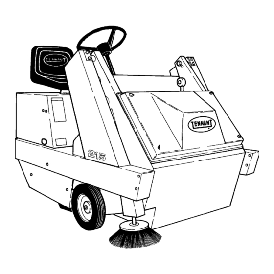
OPERATION OPERATION OF CONTROLS 03062 MACHINE COMPONENTS A. Operator Seat E. Hopper B. Steering Wheel F. Side Brush C. Instrument Panel G. Access Door D. Filter Cover H. Seat Support 215 MM157 (11- -91) -
Page 13: Instrument Panel Symbols
Side Brush Down Side Brush Up Main Brush Down Main Brush Up Main Brush Extra Down Pressure Hopper Door Close Hopper Door Open Hopper Up Hopper Down Filter Shaker Start Hazard Light Operational Lights Key Switch 215 MM157 (4- -90) -
Page 14: Controls And Instruments
F. Hazard Light Switch P. Side Brush Lever G. Lights Switch Q. Steering Wheel H. Filter Shaker Switch R. Main Brush Adjustment Knob Hopper Door Switch S. Circuit Breakers J. Hopper Switch T. Parking Brake Release Lever 215 MM157 (11- -91) -
Page 15: Brake Pedal
To release the parking brake, pull the release lever. Always park on a level surface, stop the engine, and set the parking brake before leaving the machine unattended and before working on the machine. 215 MM157 (4- -90) -
Page 16: Hopper Door Switch
Brush Extra Down Pressure) adjusts the main brush contact with the floor. To increase main brush contact with the floor, turn the knob to the right. To decrease main brush contact with the floor, turn the knob to the left. 215 MM157 (4- -90) -
Page 17: Circuit Breakers And Fuses
--- Multi-Level Dump fuses than those specified in this manual. Model The circuit breakers are located on the instrument panel. The fuse is located on the fan support bracket. 03067 CIRCUIT BREAKERS A. Instrument Panel B. Circuit Breakers 215 MM157 (4- -90) -
Page 18: Hopper Support Bar
TO DISENGAGE HOPPER SUPPORT BAR 1. Raise the hopper. 2. Place the support bar in its storage position. 3. Lower the hopper. 03068 ENGAGED HOPPER SUPPORT BAR - - LOW DUMP MODEL A. Lintel B. Support Bar 2-10 215 MM157 (11- -91) -
Page 19: Machine Operation
7. Drive the machine to the area to be swept. Check service records to determine service requirements. TO START MACHINE NOTE: Before starting machine, perform the pre-start checks. 1. LPG machines: Slowly open the liquid service valve. 2-11 215 MM157 (4- -90) -
Page 20: To Sweep
FOR SAFETY: When Using Machine, Go bottom (Hopper Door Open) position to Slow On Grades And Slippery Surfaces. dump the hopper. The maximum rated climb and descent angle is 2-12 215 MM157 (4- -90) -
Page 21: Machine Troubleshooting
Transmission drive belt slipping or Check and adjust or replace broken Transmission malfunction Repair or replace Transmission Wheel drive chains or sprockets Check and replace broken Jackshaft belt broken or slipping Check and adjust or replace 2-13 215 MM157 (4- -90) -
Page 22: Transporting Machine
FOR SAFETY: When Servicing Machine, Jack 10. Remove the jack stands from under the Machine Up At Designated Locations Only. machine. Block Machine Up With Jack Stands. 11. Lower the machine. 12. Remove the blocks from the tires. 2-14 215 MM157 (11- -91) -
Page 23: Machine Tie-Downs
REAR TIE-DOWN LOCATION A. Tie-Down Hole When transporting the machine on a trailer or in a truck, be sure to engage the machine parking brake and block the machine tires to prevent the machine from rolling. 2-15 215 MM157 (4- -90) -
Page 24: Machine Storage
8. Remove the spark plug and pour 1 oz (30 cc) of new engine oil into the cylinder. 9. Crank the engine to distribute the oil, then replace the spark plug. 10. Clean the engine cooling fins. 2-16 215 MM157 (4- -90) - Page 25 ......3-39 BELT ......3-20 215 MM157 (6- -88)
- Page 26 MAINTENANCE 215 MM157 (6- -88)
-
Page 27: Recommended First 20-Hour Machine Inspection
After the first 20 hours of operation, the following 2. Check the floor skirts to floor clearance. procedures are recommended: 3. Check the side brush and main brush 1. Check the brush pattern for correct brush patterns. adjustment. 215 MM157 (6- -88) -
Page 28: Maintenance Chart
Change oil Clean air filter precleaner element Clean cooling fins Transmission Check oil level Hydraulic reservoir Check fluid level HYDO 50 Hours Intermediate side brush Check tension and wear belt Engine belt Check tension and wear 215 MM157 (6- -88) - Page 29 Check starter motor brushes EO -- Engine oil HYDO -- Tennant Company or approved hydraulic fluid SPL -- Special lubricant, Lubriplate EMB grease (TENNANT part No. 01433--1) NOTE: More frequent intervals may be required in extremely dusty conditions. 215 MM157 (6- -88)
-
Page 30: Lubrication
The differential drives the two front wheels. Two grease fittings are located on the differential housing for lubrication. The differential should be lubricated by applying Lubriplate EMB grease TENNANT Part No. 01433--1 to the grease fittings after every 100 hours of operation. 215 MM157 (4- -90) -
Page 31: Steering Gear
The top lift cylinder bearing should be lubricated lubricated by applying Lubriplate EMB grease by applying Lubriplate EMB grease TENNANT TENNANT Part No. 01433--1 to the grease fitting Part No. 01433--1 to the grease fitting after every after every 100 hours of operation. -
Page 32: Hydraulics
TENNANT Hydraulic Fluid, as well as the other features described. Do not substitute automatic transmission fluid for hydraulic fluid. -
Page 33: Hydraulic Schematic
MAINTENANCE 03078 HYDRAULIC SCHEMATIC 215 MM157 (6- -88) -
Page 34: Engine
A. Foam Precleaner unfiltered air. B. Dry Cartridge-Type Air Filter C. Wing Nut D. Filter Cover 5. Remove the foam precleaner. 6. Wash the foam precleaner in liquid detergent and water. 3-10 215 MM157 (11- -91) -
Page 35: Fuel System -- Gasoline
The carburetor should be adjusted with the fuel combustion chamber air flow. tank approximately one-half full and with the engine running at approximately 2350 RPM. Turn the main fuel adjusting needle valve out until the 3-11 215 MM157 (11- -91) -
Page 36: Fuel Tanks
The valve must be closed except ratherthan liquid. when in service. 3-12 215 MM157 (11- -91) -
Page 37: To Change An Lpg Fuel Tank
13. Open the tank service valve slowly and check for leaks. If an LPG leak is found, close the service valve immediately and notify the appropriate personnel. 14. If no leaks are found, the engine is ready to start. 3-13 215 MM157 (NIL) -
Page 38: Fuel Filter Lock
If any malfunction is noted, completely disassemble the regulator. Clean all of the parts in alcohol. Inspect all of the parts and replace where needed. Carefully reassemble the regulator with the seal repair kit. Check for proper operation. 3-14 215 MM157 (11- -91) -
Page 39: Lpg Fuel Troubleshooting
Plugged fuel filter Replace filter Kinked or restricted fuel line Straighten or replace fuel line Engine out of tune Tune-up engine Restricted air filter Clean or replace air filter element Regulator maladjusted Adjust regulator 3-15 215 MM157 (6- -88) -
Page 40: Electrical System
(.4 to .5 mm) Valve clearances, cold: in- 0.006 to 0.008 in STARTER take (0.15 to 0.20mm) The starter motor brushes must be inspected after exhaust 0.017 to 0.019 in every 400 hours of operation. (0.43 to 0.48mm) 3-16 215 MM157 (6- -88) -
Page 41: Electrical System
80_ F (27_ C). plates, but do not overfill. Never add acid to batteries, only water. Keep vent plugs firmly in place at all times, except when adding water or taking hydrometer readings. 3-17 215 MM157 (11- -91) -
Page 42: Electrical Schematic
MAINTENANCE 03077 ELECTRICAL SCHEMATIC 3-18 215 MM157 (6- -88) -
Page 43: Belts And Chains
1. Stop the engine and set the parking brake. B. Tension Bolt C. Jam Nut FOR SAFETY: Before Leaving Or Servicing Machine; Stop On Level 4. Remove the existing belt. Surface, Set Parking Brake, And Turn Off Machine. 2. Open the seat support. 3-19 215 MM157 (4- -90) -
Page 44: Transmission Belt
50 hours of 9. Check the alignment as described in DRIVE operation as described in DRIVE CHAIN AND CHAIN AND BELT ALIGNMENT AND BELT ALIGNMENT AND TENSIONING. TENSIONING. 10. Close the seat support. 3-20 215 MM157 (4- -90) -
Page 45: Jackshaft Belt
7. Check the alignment and tension the belt as described in DRIVE CHAIN AND BELT ALIGNMENT AND TENSIONING. 03552 BELT ADJUSTMENT BOLT 8. Close the seat support. A. Jackshaft Bracket B. Adjustment Bolt C. Jam Nut 3-21 215 MM157 (4- -90) -
Page 46: Intermediate Side Brush Belt
12. Reinstall the right side access door and C. Side Brush Belt machine frame plugbutton. 6. Remove the existing belt. 13. Close the seat support. 7. Position the rear of the new belt over the rear sheave. 3-22 215 MM157 (4- -90) -
Page 47: Main Brush Belt
B. Belt Idler Spring locking collars, align the sprockets, and C. Main Brush Belt tighten the locking collars. D. Belt Guard 5. Disconnect the main brush belt idler spring. 3-23 215 MM157 (4- -90) - Page 48 If they are not lined up, loosen the sheave set screws, align the sheave, and retighten the set screws. The belt is automatically tensioned by an idler spring assembly. 3-24 215 MM157 (6- -88)
- Page 49 To adjust tension, adjust the belt adjustment bolt under the jackshaft bracket. Tighten jam nut. 03551 FRONT ADJUSTMENT BOLT A. Engine B. Adjustment Bolt 03552 C. Jam Nut ADJUSTMENT BOLT A. Jackshaft Bracket B. Adjustment Bolt 3-25 215 MM157 (6- -88)
-
Page 50: Static Drag Chain
Loosen the adjustable idler bolt and slide the idler forward to reduce spring length or backward to increase spring length. Tighten the adjustable idler bolt and rehook the belt tension spring. Repeat procedure as required. 17. Close the seat support. 3-26 215 MM157 (6- -88) -
Page 51: Debris Hopper And Dust Filter
Servicing Machine; Stop On Level Surface, Set Parking Brake, And Turn Off Machine. 2. Unthread the four front filter cover screws and remove the front filter cover. 03084 HOPPER STOP BOLTS A. Hopper B. Stop Bolts 3-27 215 MM157 (4- -90) - Page 52 Plug the shaker motor 3. Unplug the shaker motor leads. Remove leads together. the shaker motor and springs assembly. Remove the dust filter. 7. Secure the front filter cover on the filter frame with the four screws. 3-28 215 MM157 (6- -88)
-
Page 53: Skirts And Seals
RIGHT SIDE SKIRT A. Retaining Strip B. Side Skirt 7. Loosen the skirt retaining strip, adjust the skirt height, and retighten the retaining strip. 8. Check the skirt clearance. 9. Reinstall the right side access door. 3-29 215 MM157 (4- -90) -
Page 54: Hopper Seals
C. Seal Retaining Strip 7. Mount the new seal or skirt to the machine with the retaining strip removed earlier. 7. Remove the seal. 8. Raise the hopper, disengage the hopper support bar, and lower the hopper. 3-30 215 MM157 (4- -90) -
Page 55: Rear Skirts
7. Slide the vertical rear skirt up or down so it is 0 to 0.12 in (0 to 5 mm) above the floor. 4. Loosen the two right side access door screws and remove the right side access 8. Retighten the retaining strip bolts. door. 3-31 215 MM157 (4- -90) -
Page 56: Hopper Lip Skirt
6. Position the new skirt on the hopper. Secure Machine; Stop On Level Surface, Set Parking it in place with the retaining strip. Brake, And Turn Off Machine. 7. Raise the hopper, disengage the hopper support bar, and lower the hopper. 3-32 215 MM157 (4- -90) -
Page 57: Brushes
Servicing Machine; Stop On Level drive plug, and out of the main brush Surface, Set Parking Brake, And Turn compartment. Off Machine. 2. Place the main brush position lever in the (Main Brush Down) position. 3-33 215 MM157 (4- -90) -
Page 58: To Install Main Brush
8. Tighten the brush idler arm retaining bolts. 00601 TAPERED MAIN BRUSH PATTERN 9. Close the left side access door. A. Main Brush Pattern 10. Check and adjust the main brush pattern as describe in TO CHECK AND ADJUST MAIN BRUSH PATTERN. 3-34 215 MM157 (4- -90) -
Page 59: Side Brush
B. Retaining Bolt turn the main brush height adjustment knob C. Side Brush Drive Shaft counterclockwise. Recheck the pattern width after making any adjustments. 4. Slide the side brush off the side brush drive shaft. 3-35 215 MM157 (4- -90) -
Page 60: To Install Side Brush
2. Insert the side brush retaining bolt through the side brush hub and shaft. 3. Thread a nut onto the threads of the bolt. 4. Tighten the nut and bolt to secure the side brush. 3-36 215 MM157 (6- -88) -
Page 61: Transmission
ATTENTION! Cleaning the transmission with high pressure water spray or live steam may allow water to enter the reservoir. A few drops of water in the system will result in loss of oil, and loss of power. 3-37 215 MM157 (6- -88) -
Page 62: Transmission Linkage
The rear stop bolt should be adjusted so that the A. Transmission threaded end of the bolt is 1 in (25 mm) from the B. Forward Stop Bolt bracket. C. Centering Spring D. Pintle Arm E. Rear Stop Bolt 3-38 215 MM157 (6- -88) -
Page 63: Brakes And Tires
03073 BRAKE ASSEMBLY A. Right Side Tire B. Brake Cable C. Clevis D. Brake Assembly 3-39 215 MM157 (6- -88) - Page 64 MAINTENANCE 3-40 215 MM157 (6- -88)
- Page 65 ....4--4 HYDRAULIC O--RING FITTING TORQUE CHART ......4--4 215 MM157 (6- -88)
- Page 66 APPENDIX 215 MM157 (6- -88)
- Page 67 32676, 0.5 ml tube. Main brush drive plug nut --- 30 ft lb (40 Nm) Locktite 271 red --- high strength thread then tighten to next slot. locking compound. TENNANTr Part No. 19857, 0.5 ml tube. 215 MM157 (6- -88)
- Page 68 NOTE: Do not use sealant on o ---ring threads. 0.62 Nm) 0.88--- 14 40 ft lb (54 0.75 Nm) 1.12--- 12 70 ft lb (95 *Aluminum bodied components 1.0 Nm) 1.31--- 12 90 ft lb (122 215 MM157 (6- -88)
Need help?
Do you have a question about the 215 and is the answer not in the manual?
Questions and answers