Aprilaire Home Comfort Control 8910W Safety & Installation Instructions
Hide thumbs
Also See for Home Comfort Control 8910W:
- Owner's manual (21 pages) ,
- Safety & installation instructions (26 pages) ,
- User manual
Table of Contents
Advertisement
ReaD anD saVe THese InsTRuCTIons
Safety &
Installation
Instructions
Table oF ConTenTs
WI-FI seTup
Wi-Fi Setup . . . . . . . . . . . . . . . . . . . . . . . . . . . . . . . . . . 2
Thermostat mounting . . . . . . . . . . . . . . . . . . . . . . . . . . . 2
recommendations . . . . . . . . . . . . . . . . . . . . . . . . . . . . . . 2
Equipment control module mounting . . . . . . . . . . . . . . 2
Thermostat wiring . . . . . . . . . . . . . . . . . . . . . . . . . . . . . 3
Remote temperature sensor (optional) . . . . . . . . . . . . . 3
Equipment control module wiring . . . . . . . . . . . . . . . . . 4
Outdoor temperature sensor (included) . . . . . . . . . . . . . 5
Optional wireless outdoor temperature sensor . . . . . . 5
Return air temperature sensor (optional) . . . . . . . . . . . 6
Leaving air temperature sensor (optional) . . . . . . . . . . 6
Conventional heat/cool single transformer . . . . . . . . . . 7
Conventional heat/cool two transformer . . . . . . . . . . . 7
Heat pump single transformer . . . . . . . . . . . . . . . . . . . . 8
Heat pump two transformer . . . . . . . . . . . . . . . . . . . . . 8
Home Comfort Control
Power and reset options . . . . . . . . . . . . . . . . . . . . . . . 10
Removal of Indoor Air Quality control buttons . . . . . . 10
Equipment type selection switch (SW1) . . . . . . . . . . . 11
Installer setup menu . . . . . . . . . . . . . . . . . . . . . . . . . . 11
Change system settings . . . . . . . . . . . . . . . . . . . . . . . . 11
HVAC installer system settings table . . . . . . . . . . 12-13
Indoor Air Quality system settings tables . . . . . . . . . . 14
Air cleaning system settings table . . . . . . . . . . . . . . 14
Humidifier system settings table . . . . . . . . . . . . . . . 14
Dehumidifier system settings table . . . . . . . . . . . . . 15
Ventilation system settings table . . . . . . . . . . . . 15-16
System test menu . . . . . . . . . . . . . . . . . . . . . . . . . 17-18
System test tables . . . . . . . . . . . . . . . . . . . . . . . . . 18-20
ReFeRenCes
Quick reference to controls & display . . . . . . . . . . 21-22
Troubleshooting . . . . . . . . . . . . . . . . . . . . . . . . . . . 22-23
Error codes . . . . . . . . . . . . . . . . . . . . . . . . . . . . . . . . . . 23
Home Comfort Control features . . . . . . . . . . . . . . . . . 23
Specifications . . . . . . . . . . . . . . . . . . . . . . . . . . . . . . . . 24
with Wi-Fi
™
Model 8910W
Advertisement
Table of Contents

Related Manuals for Aprilaire Home Comfort Control 8910W


Summary of Contents for Aprilaire Home Comfort Control 8910W
-
Page 1: Table Of Contents
Home Comfort Control with Wi-Fi ™ Model 8910W ReaD anD saVe THese InsTRuCTIons Safety & Installation Instructions Table oF ConTenTs WI-FI seTup poWeR & ReseT opTIons Power and reset options . . . . . . . . . . . . . . . . . . . . . . . 10 Wi-Fi Setup . -
Page 2: Wi-Fi Setup
WI-FI seTup InsTallaTIon For detailed instructions for connecting the Home Comfort Control ™ to a Wi-Fi network and registering it to an THeRMosTaT WIRInG Aprilaire account, refer to the Wi-Fi Quick Start Guide included in the box. Wire specifications: 18-24 gauge thermostat wire InsTallaTIon Installation notes: THeRMosTaT InsTallaTIon loCaTIon ReCoMMenDaTIons T1 T2 • E nsure power at the HVAC equipment is off. -
Page 3: Equipment Control Module Wiring
InsTallaTIon InsTallaTIon eQuIpMenT ConTRol MoDule WIRInG ouTDooR TeMpeRaTuRe sensoR (InCluDeD) Outdoor temperature can be measured by installing an 8052 sensor to the ODT terminals and enabling the outdoor sensor in the installer set-up menu. When an outdoor sensor is installed, the features below will be enabled. In heat pump mode the outdoor temperature sensor can be used to efficiently utilize an air source heat pump: • W hen the outdoor temperature is less than the Low Balance Point, the heat pump will be locked out and only auxiliary heating will be used to provide heating. -
Page 4: Return Air Temperature Sensor (Optional)
40°F TRANSFORMER and less than 100°F . 1 . Locate the Aprilaire Model 8052 sensor THERMOSTAT in the return trunk . 2 . Mount the sensor according to the... -
Page 5: Heat Pump Single Transformer
HVaC WIRInG DIaGRaMs InDooR aIR QualITy WIRInG DIaGRaMs HeaT puMp sInGle TRansFoRMeR (use JuMpeR WIRe) InDooR aIR QualITy WIRInG WITH sepaRaTe TRansFoRMeRs TRANSFORMER HUMIDIFIER HEAT PUMP TRANSFORMER THERMOSTAT DHnc HEATING HEATING DEHUMIDIFIER TRANSFORMER REVERSING VALVE NORMALLY COMPRESSOR CLOSED DAMPER COMPRESSOR TRANSFORMER REVERSING VALVE PILOT RELAY FOR... -
Page 6: Power & Reset Options
poWeR & ReseT opTIons seTup & TesTInG The equipment control module is powered from 24VAC . eQuIpMenT Type seleCTIon sWITCH (sW1) The thermostat is powered from the equipment control RESET module . In the case of power loss the thermostat will This Home Comfort Control has the option of being used BUTTON maintain the clock for 24 hours . -
Page 7: Hvac Installer System Settings Table
Three (only available in Heat/Cool) Enable predefined setpoint(s) using a single button 06 . Heat/Cool: Heating Stages Heat/Cool: Number of Heat Stages. press in the Aprilaire mobile and web apps . The Heat Pump: Aux Heat Heat Pump: Number of Auxiliary Heat Stages. predefined setpoint(s) is set by the user in the app . Stages... -
Page 8: Indoor Air Quality System Settings Tables
seTup & TesTInG seTup & TesTInG Dehumidifier system settings Table InDooR aIR QualITy sysTeM seTTInGs Tables Factory default setting (bold) The following tables contain the Indoor Air Quality system settings and their details . Default settings are shown in system setting Description and setting range bold . -
Page 9: System Test Menu
seTup & TesTInG seTup & TesTInG Ventilation system settings Table (continued) sysTeM TesT Menu Factory default setting (bold) The system test menu is used to test a system after installation . The outputs of the Home Comfort Control can be system setting Description and setting range... -
Page 10: System Test Tables
seTup & TesTInG seTup & TesTInG sysTeM TesT Menu sysTeM TesT Tables (ConTInueD) (ConTInueD) While the equipment test is active the corresponding test information will be shown . Heat pump Heating equipment Test (electric Heat) press [neXT] to accept the selection and proceed to the next test selection. Compressor stages stages 1st Stage Test 2nd Stage Test HUMIDITY... -
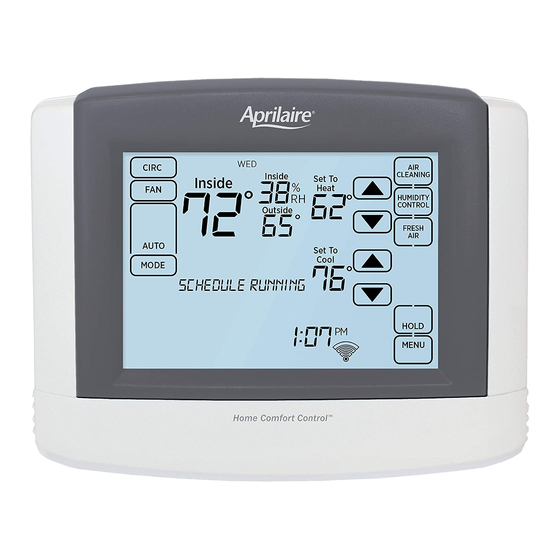
Page 11: Quick Reference To Controls & Display
seTup & TesTInG QuICK ReFeRenCe To ConTRols & DIsplay sysTeM TesT Tables HoMe sCReen (ConTInueD) ROOM TEMPERATURE CURRENT DAY OUTDOOR TEMPERATURE TEMPERATURE SETTING ROOM RELATIVE HUMIDITY Heat / Cool Cooling equipment Test AIR CLEANING BUTTON FAN MODE (ENTERS EVENT-BASED ™ SETTING 1st Stage Test CLEANING CONTROL SCREEN) 2nd Stage Test HUMIDITY CONTROL BUTTON FAN MODE BUTTON (ENTERS HUMIDITY CONTROL 3rd Stage Test... -
Page 12: Troubleshooting
QuICK ReFeRenCe To ConTRols & DIsplay TRoublesHooTInG eQuIpMenT ConTRol MoDule leDs HeaT/Cool boTH on aT saMe TIMe “HeaTInG” Is noT DIsplayeD • C heck SW1 (Equipment Type), to make sure it is set • C heck Installer System Setting 04 (Control Setup) is poWeR/sTaTus – On solid during normal operation . Flashes to match the installed heating/cooling equipment . set correctly . -
Page 13: Specifications
Cool: 50° to 99°F (10° to 37°C) Humidification: 10% to 50% R .H . Setpoint humidity range Dehumidification: 40% to 90% R .H . P.O. Box 1467 • Madison, WI 53701-1467 • Phone: 800/334-6011 • Fax: 608/257-4357 www.aprilairepartners.com 61001131 4 .15 U.S. Patent Numbers 8,146,376, 8,596,078 and other patents pending. B2206504B © 2015 Aprilaire – A division of Research Products Corporation...
Need help?
Do you have a question about the Home Comfort Control 8910W and is the answer not in the manual?
Questions and answers