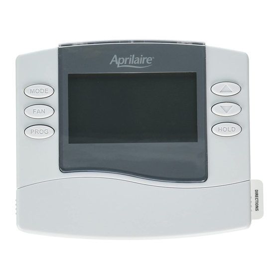
Aprilaire 8400 Series Safety & Installation Instructions
Hide thumbs
Also See for 8400 Series:
- Safety & installation instructions (28 pages) ,
- Installation instructions manual (28 pages) ,
- Owner's manual (12 pages)
Summary of Contents for Aprilaire 8400 Series
- Page 1 8400 Series Thermostats Safety & Installation Instructions READ AND SAVE THESE INSTRUCTIONS...
-
Page 2: Table Of Contents
TABLE OF CONTENTS INSTALLATION INSTALLATION INSTALLATION LOCATION RECOMMENDATIONS Installation location recommendations . . . . . . . . . . . . . . . . . . . . . . . . . . . . . . . . . . . . . . . . . . . . . . . . . . . . . . . . . . . . . . . .3 Thermostat should be mounted: Do not mount thermostat: Outdoor temperature sensor (optional) . -
Page 3: Outdoor Temperature Sensor (Optional)
INSTALLATION INSTALLATION OUTDOOR TEMPERATURE SENSOR (OPTIONAL) THERMOSTAT MOUNTING POWER & RESET OPTIONS Outdoor temperature can be measured by attaching an • Install on side of building out of direct sunlight The thermostat is dual power . It can either be AC or 8052 sensor to the S1 and S2 terminals . -
Page 4: Wiring Terminal
INSTALLATION INSTALLATION WIRING TERMINAL WIRING – MODEL 8463 & 8444 SINGLE WIRING – MODEL 8463 & 8444 TWO TRANSFORMER (USE JUMPER WIRE) TRANSFORMERS (REMOVE JUMPER WIRE) Wire specifications RC – 24 VAC supply cooling* R – 24 VAC supply heating* 18-24 gauge thermostat wire W –... - Page 5 INSTALLATION INSTALLATION WIRING – MODEL 8465 & 8446 SINGLE WIRING – MODEL 8465 & 8446 TWO WIRING – MODEL 8466 & 8448 SINGLE WIRING – MODEL 8466 & 8448 TWO TRANSFORMER (USE JUMPER WIRE) TRANSFORMERS (REMOVE JUMPER WIRE) TRANSFORMER (USE JUMPER WIRE) TRANSFORMERS (REMOVE JUMPER WIRE) FOR HEAT/COOL SYSTEM FOR HEAT/COOL SYSTEM...
-
Page 6: Setup & Testing
INSTALLATION SETUP & TESTING WIRING – MODEL 8466 & 8448 SINGLE WIRING – MODEL 8466 & 8448 TWO SYSTEM SETUP INSTRUCTIONS TRANSFORMER (USE JUMPER WIRE) TRANSFORMERS (REMOVE JUMPER WIRE) The following instructions show how to enter the system setup menu and change settings . The table on the FOR HEAT PUMP SYSTEM FOR HEAT PUMP SYSTEM following pages lists the settings and their details . - Page 7 SETUP & TESTING SETUP & TESTING SYSTEM SETUP INSTRUCTIONS SYSTEM SETUP INSTRUCTIONS (CONTINUED) (CONTINUED) Thermostat models 8448 & 8466 have the option of being used in heat pump or heat/cool systems . The equipment System setting Setting range, default in bold type switch located on the back of the thermostat’s face is used to select this .
- Page 8 SETUP & TESTING SETUP & TESTING SYSTEM SETUP INSTRUCTIONS SYSTEM SETUP INSTRUCTIONS (CONTINUED) (CONTINUED) System setting Setting range, default in bold System setting Setting range, default in bold 1°F (0.5°C) 17 High Balance Pt . (8446, 8448HP, 8465, 8466HP) 65°F (18°C) 09 1st stage differential 1°F to 4°F (0 .5°C to 2°C) System setting 05 must be enabled...
-
Page 9: System Test Mode
SETUP & TESTING SETUP & TESTING SYSTEM TEST MODE SYSTEM TEST MODE (CONTINUED) The system test mode is used to test a system after installation . The outputs of the thermostat can be manually How to enter the system test menu Press to turn on the output (01) . - Page 10 SETUP & TESTING SETUP & TESTING Test steps for 8444 & 8463 Test steps for 8448HC & 8466HC System Setting Display (Output) System Setting Display (Output) Step Key Input Step Key Input HEATING COOLING FAN ON HEATING HEATING COOLING COOLING FAN ON ON (W) ON (Y)
- Page 11 SETUP & TESTING SETUP & TESTING Test steps for 8446 & 8465 Test steps for 8448HP & 8466HP System Setting Display (Output) System Setting Display (Output) 01 AUX 01 AUX 02 AUX Step Key Input Step Key Input HEATING COOL/HEAT FAN ON HEATING HEATING...
-
Page 12: Quick Reference To Controls & Display
QUICK REFERENCE TO CONTROLS & DISPLAY QUICK REFERENCE TO CONTROLS & DISPLAY NON-PROGRAMMABLE MODELS (8444, 8446, 8448) PROGRAMMABLE MODELS (8463, 8465, 8466) CURRENT INDOOR TEMPERATURE CURRENT INDOOR TEMPERATURE OUTDOOR TEMPERATURE (OPTIONAL) CURRENT TIME OUTDOOR TEMPERATURE (OPTIONAL) SYSTEM MODE SYSTEM MODE SETTING SETTING TEMPERATURE SETTING... -
Page 13: Thermostat Features
THERMOSTAT FEATURES TROUBLESHOOTING ALL 8400 SERIES THERMOSTATS PROGRAMMABLE MODELS ONLY DISPLAY IS BLANK HEATING SYSTEM DOES NOT RESPOND (8463, 8465, 8466) (“HEATING” APPEARS ON SCREEN) • Large, clear, backlit display is easy to read – even • Check circuit breaker and reset if necessary . -
Page 14: Troubleshooting
TROUBLESHOOTING SPECIFICATIONS COOLING SYSTEM DOES NOT RESPOND HEAT/COOL BOTH ON AT SAME TIME Environment (“COOLING” APPEARS ON SCREEN) • Check SW1 (Equipment Type), to make sure it is set Operating: 32° to 120°F (0° to 48 .9°C) • Check for 24 VAC at the equipment on the secondary to match the installed heating/cooling equipment Temperature Shipping: -30°... -
Page 15: Specifications
Temperature setting range Cool: 50° to 99°F (10° to 37°C) P .O . Box 1467 • Madison, WI 53701-1467 • Phone: 800/334-6011 • Fax: 608/257-4357 www.aprilairepartners.com 61000652 8 .16 B2204777E © 2016 Aprilaire – A division of Research Products Corporation...


Need help?
Do you have a question about the 8400 Series and is the answer not in the manual?
Questions and answers