Aprilaire Home Comfort Control 8910 Safety & Installation Instructions
Hide thumbs
Also See for Home Comfort Control 8910:
- User manual ,
- Owner's manual (19 pages) ,
- Safety & installation instructions (13 pages)
Table of Contents
Advertisement
ReaD anD saVe THese InsTRuCTIons
Safety &
Installation
Instructions
Table of ConTenTs
Thermostat mounting . . . . . . . . . . . . . . . . . . . . . . . . . . . 2
recommendations . . . . . . . . . . . . . . . . . . . . . . . . . . . . . . 2
Equipment control module mounting . . . . . . . . . . . . . . 2
Thermostat wiring . . . . . . . . . . . . . . . . . . . . . . . . . . . . . 3
Remote temperature sensor (optional) . . . . . . . . . . . . . 3
Equipment control module wiring . . . . . . . . . . . . . . . . . 4
Outdoor temperature sensor . . . . . . . . . . . . . . . . . . . . . 5
Optional wireless outdoor temperature sensor . . . . . . 5
Return air temperature sensor (optional) . . . . . . . . . . . 6
Leaving air temperature sensor (optional) . . . . . . . . . . 6
Conventional heat/cool single transformer . . . . . . . . . . 7
Conventional heat/cool two transformer . . . . . . . . . . . 7
Heat pump single transformer . . . . . . . . . . . . . . . . . . . . 8
Heat pump two transformer . . . . . . . . . . . . . . . . . . . . . 8
Home Comfort Control
PoWeR & ReseT oPTIons
Power and reset options . . . . . . . . . . . . . . . . . . . . . . . 10
Equipment type selection switch (SW1) . . . . . . . . . . . 11
Installer setup menu . . . . . . . . . . . . . . . . . . . . . . . . . . 11
Change system settings . . . . . . . . . . . . . . . . . . . . . . . . 11
HVAC installer system settings table . . . . . . . . . . 12-13
Indoor Air Quality system settings tables . . . . . . . . . . 14
Air cleaning sytem settings table . . . . . . . . . . . . . . 14
Humidifier system settings table . . . . . . . . . . . . . . . 14
Dehumidifier system settings table . . . . . . . . . . . . . 15
Ventilation system settings table . . . . . . . . . . . . 15-16
System test menu . . . . . . . . . . . . . . . . . . . . . . . . . 17-18
System test tables . . . . . . . . . . . . . . . . . . . . . . . . . 18-20
RefeRenCes
Quick reference to controls & display . . . . . . . . . . 21-22
Troubleshooting . . . . . . . . . . . . . . . . . . . . . . . . . . . 22-23
Error codes . . . . . . . . . . . . . . . . . . . . . . . . . . . . . . . . . . 23
Home Comfort Control features . . . . . . . . . . . . . . . . . 23
Specifications . . . . . . . . . . . . . . . . . . . . . . . . . . . . . . . . 24
™
Model 8910
Advertisement
Table of Contents

Subscribe to Our Youtube Channel
Related Manuals for Aprilaire Home Comfort Control 8910


Summary of Contents for Aprilaire Home Comfort Control 8910
-
Page 1: Table Of Contents
Home Comfort Control ™ Model 8910 ReaD anD saVe THese InsTRuCTIons Safety & Installation Instructions Table of ConTenTs InsTallaTIon PoWeR & ReseT oPTIons Power and reset options . . . . . . . . . . . . . . . . . . . . . . . 10 Thermostat installation location recommendations . -
Page 2: Installation
InsTallaTIon InsTallaTIon THeRMosTaT InsTallaTIon loCaTIon ReCoMMenDaTIons THeRMosTaT WIRIng Thermostat should be mounted: Do not mount thermostat: Wire specifications: • O n an interior wall, in a frequently occupied space. • B ehind doors, in corners or other dead air spaces. 18-24 gauge thermostat wire • A pproximately 5‘ above floor. • I n direct sunlight, near lighting fixtures, or other Installation notes: appliances that give off heat . -
Page 3: Equipment Control Module Wiring
InsTallaTIon InsTallaTIon eQuIPMenT ConTRol MoDule WIRIng ouTDooR TeMPeRaTuRe sensoR Outdoor temperature can be measured by installing an 8052 sensor (included) to the ODT terminals and enabling the outdoor sensor in the installer set-up menu. When an outdoor sensor is installed, the features below will be enabled. In heat pump mode the outdoor temperature sensor can be used to efficiently utilize an air source heat pump: • W hen the outdoor temperature is less than the Low Balance Point, the heat pump will be locked out and only auxiliary heating will be used. -
Page 4: Return Air Temperature Sensor (Optional)
40°F TRANSFORMER and less than 100°F . 1 . Locate the Aprilaire Model 8052 sensor THERMOSTAT in the return trunk . 2 . Mount the sensor according to the... -
Page 5: Hvac Wiring Diagrams
HVaC WIRIng DIagRaMs InDooR aIR QualITy WIRIng DIagRaMs HeaT PuMP sIngle TRansfoRMeR (use JuMPeR WIRe) InDooR aIR QualITy WIRIng WITH sePaRaTe TRansfoRMeRs TRANSFORMER HUMIDIFIER HEAT PUMP TRANSFORMER THERMOSTAT DHnc HEATING HEATING DEHUMIDIFIER TRANSFORMER REVERSING VALVE NORMALLY COMPRESSOR CLOSED DAMPER COMPRESSOR TRANSFORMER REVERSING VALVE PILOT RELAY FOR... -
Page 6: Setup & Testing
PoWeR & ReseT oPTIons seTuP & TesTIng The equipment control module is powered from eQuIPMenT TyPe seleCTIon sWITCH (sW1) 24VAC . The thermostat is powered from the equipment RESET interface module and has a battery back-up option for BUTTON This Home Comfort Control has the option of being used the clock . -
Page 7: Hvac Installer System Settings Table
seTuP & TesTIng seTuP & TesTIng HVaC InsTalleR sysTeM seTTIngs Table HVaC InsTalleR sysTeM seTTIngs Table (ConTInueD) The following table contains the system settings and their details . Default settings are shown in bold . Some settings factory default setting (bold) are only available dependent upon the value of other settings . -
Page 8: Indoor Air Quality System Settings Tables
seTuP & TesTIng seTuP & TesTIng Dehumidifier system settings Table InDooR aIR QualITy sysTeM seTTIngs Tables factory default setting (bold) The following tables contain the Indoor Air Quality system settings and their details . Default settings are shown in system setting Description and setting range bold . -
Page 9: System Test Menu
seTuP & TesTIng seTuP & TesTIng Ventilation system settings Table (continued) sysTeM TesT Menu factory default setting (bold) The system test menu is used to test a system after installation . The outputs of the Home Comfort Control can be system setting Description and setting range... -
Page 10: System Test Tables
seTuP & TesTIng seTuP & TesTIng sysTeM TesT Menu sysTeM TesT Tables (ConTInueD) (ConTInueD) While the equipment test is active the corresponding test information will be shown . Heat Pump Heating equipment Test (electric Heat) Press [neXT] to accept the selection and proceed to the next test selection. Compressor stages stages 1st Stage Test 2nd Stage Test HUMIDITy... -
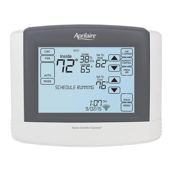
Page 11: Quick Reference To Controls & Display
seTuP & TesTIng QuICK RefeRenCe To ConTRols & DIsPlay sysTeM TesT Tables HoMe sCReen (ConTInueD) ROOM TEMPERATURE CURRENT DAy OUTDOOR TEMPERATURE TEMPERATURE SETTING ROOM RELATIVE HUMIDITy Heat / Cool Cooling equipment Test AIR CLEANING BUTTON FAN MODE (ENTERS EVENT-BASED ™ BUTTON 1st Stage Test CLEANING CONTROL SCREEN) 2nd Stage Test HUMIDITy CONTROL BUTTON FAN MODE SETTING (ENTERS HUMIDITy CONTROL 3rd Stage Test... -
Page 12: Troubleshooting
QuICK RefeRenCe To ConTRols & DIsPlay TRoublesHooTIng eQuIPMenT ConTRol MoDule leDs HeaT/Cool boTH on aT saMe TIMe “HeaTIng” Is noT DIsPlayeD • C heck SW1 (Equipment Type), to make sure it is set • C heck Installer System Setting number 05 PoWeR/sTaTus – On solid during normal operation . Flashes to match the installed heating/cooling equipment . (Control Setup) is set correctly . -
Page 13: Specifications
Cool: 50° to 99°F (10° to 37°C) Humidification: 10% to 50% R .H . Setpoint humidity range Dehumidification: 50% to 90% R .H . P.O. Box 1467 • Madison, WI 53701-1467 • Phone: 800/334-6011 • Fax: 608/257-4357 www.aprilairepartners.com 61000850 2 .12 Patent Pending B2205646B © 2012 Aprilaire – A division of Research Products Corporation...
Need help?
Do you have a question about the Home Comfort Control 8910 and is the answer not in the manual?
Questions and answers