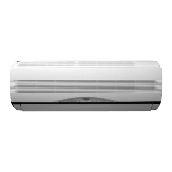
Panasonic CS-E9BKP Service Manual
Room air conditioner
Hide thumbs
Also See for CS-E9BKP:
- Service manual (89 pages) ,
- Operating instructions manual (83 pages) ,
- Руководство по эксплуатации (14 pages)
Table of Contents
Advertisement
CONTENTS
CS-E9BKP CU-E9BKP5
CS-E12BKP CU-E12BKP5
Page
2
3
6
10
12
13
14
16
36
© 2001 Matsushita Air-Conditioning Corp. Sdn. Bhd.
(183914D) All rights reserved. Unauthorized copying
and distribution is a violation of law.
Order No: MAC0112083C2
Room Air Conditioner
Page
41
52
61
70
73
74
75
76
77
Advertisement
Table of Contents

Related Manuals for Panasonic CS-E9BKP


Summary of Contents for Panasonic CS-E9BKP
-
Page 1: Table Of Contents
Order No: MAC0112083C2 Room Air Conditioner CS-E9BKP CU-E9BKP5 CS-E12BKP CU-E12BKP5 CONTENTS Page Page 1 Features 10 Installation And Servicing Air Conditioner Using R410A 2 Functions 11 Installation Instructions 3 Product Specifications 12 Servicing Information 4 Dimensions 13 Technical Data 5 Refrigeration Cycle Diagram... -
Page 2: Features
CS-E9BKP CU-E9BKP5 / CS-E12BKP CU-E12BKP5 1 Features • Product • Serviceability − Microcomputer-controlled − Washable Front Panel compressor operating frequency − Breakdown Self Diagnosis function − Vertical and Horizontal Airflow Directions − Five modes of operation selection • Environmental Protection −... -
Page 3: Functions
CS-E9BKP CU-E9BKP5 / CS-E12BKP CU-E12BKP5 2 Functions Remote Control Illuminable buttons FAN SPEED Indoor Fan Speed Selection • • Medium- • Medium OFF/ON • Medium+ • High Operation OFF / ON • Automatic Fan Speed AUTO TEMP MODE Room Temperature Setting Operation Mode Selection •... - Page 4 CS-E9BKP CU-E9BKP5 / CS-E12BKP CU-E12BKP5 Indoor Unit Automatic Operation Switch Five Operation Modes • Press for < 5s to run Automatic Operation. • Automatic, Heating, Cooling, Soft Dry (Used when the remote control cannot be used.) and Fan Operation. • Press continuously for 5s and < 8s to run Forced Cooling Operation.
- Page 5 CS-E9BKP CU-E9BKP5 / CS-E12BKP CU-E12BKP5 Outdoor Unit Breakdown Self Diagnosis Function Time Delay Safety Control Low Pressure Control (Gas Leakage Detection) 30 seconds Forced Operation Indoor Power Relay Control High Pressure Control Automatic Restart Control Total Running Current Control Deodorizing Control...
-
Page 6: Product Specifications
CS-E9BKP CU-E9BKP5 / CS-E12BKP CU-E12BKP5 3 Product Specifications Unit CS-E9BKP CU-E9BKP5 Cooling Capacity 2.6 (0.60 - 3.00) kcal/h 2,240 (520 - 2,580) Heating Capacity 3.6 (0.60 - 5.00) kcal/h 3,100 (520 - 4,300) Moisture Removal Pint/h (3.4) Power Source Phase... - Page 7 CS-E9BKP CU-E9BKP5 / CS-E12BKP CU-E12BKP5 Power Cord Length 2.1 m — Number of core-wire 3 core wires × 1.0 mm — Dimensions Height inch (mm) 10 - 31/32 (275) 21 - 9/32 (540) Width inch (mm) 31 - 15/32 (799)
- Page 8 CS-E9BKP CU-E9BKP5 / CS-E12BKP CU-E12BKP5 Unit CS-E12BKP CU-E12BKP5 Cooling Capacity 3.45 (0.60 - 4.00) kcal/h 2,970 (520 - 3,440) Heating Capacity 4.80 (0.60 - 6.50) kcal/h 4,130 (520 - 5,590) Moisture Removal Pint/h (4.2) Power Source Phase Single Cycle Airflow Method...
- Page 9 CS-E9BKP CU-E9BKP5 / CS-E12BKP CU-E12BKP5 Dimensions Height inch (mm) 10 - 31/32 (275) 21 - 9/32 (540) Width inch (mm) 31 - 15/32 (799) 27 - 17/32 (980) Depth inch (mm) 7 - 27/32 (210) 11 - 7/32 (289) Net Weight lb (kg) 20 (9.0)
-
Page 10: Dimensions
CS-E9BKP CU-E9BKP5 / CS-E12BKP CU-E12BKP5 4 Dimensions... - Page 11 CS-E9BKP CU-E9BKP5 / CS-E12BKP CU-E12BKP5...
-
Page 12: Refrigeration Cycle Diagram
CS-E9BKP CU-E9BKP5 / CS-E12BKP CU-E12BKP5 5 Refrigeration Cycle Diagram... -
Page 13: Block Diagram
CS-E9BKP CU-E9BKP5 / CS-E12BKP CU-E12BKP5 6 Block Diagram... -
Page 14: Wiring Diagram
CS-E9BKP CU-E9BKP5 / CS-E12BKP CU-E12BKP5 7 Wiring Diagram... - Page 15 CS-E9BKP CU-E9BKP5 / CS-E12BKP CU-E12BKP5...
-
Page 16: Operation Details
CS-E9BKP CU-E9BKP5 / CS-E12BKP CU-E12BKP5 8 Operation Details 8.1. BASIC FUNCTION Inverter control, which equipped with a microcomputer in determining the most suitable operating mode as time passes, automatically adjust output power for maximum comfort always. In order to achieve the suitable operating mode, the microcomputer maintains the set temperature by measuring the temperature of the environment and performing temperature shifting. - Page 17 CS-E9BKP CU-E9BKP5 / CS-E12BKP CU-E12BKP5 Table (a): Auto Operation Mode Setting Mode Shift: Temperature Shift (K) E9BKP E12BKP Cooling/Soft Dry → Heating -2.0 -2.0 Heating → Cooling/Soft Dry +2.0 +2.0 Table (b): Outdoor Air Temperature Shifting Mode: Outdoor Temperature, X (°C):...
- Page 18 CS-E9BKP CU-E9BKP5 / CS-E12BKP CU-E12BKP5 8.1.2. Frequency Instruction for Compressor Operation Operation of compressor is based on instructed frequency, continuously from indoor unit´s microcomputer after performing temperature sampling and judgment. There are total 30 different frequency values, which listed as Table on Frequency Number, to be instructed based on the...
- Page 19 CS-E9BKP CU-E9BKP5 / CS-E12BKP CU-E12BKP5 Table on Shifting Frequency Zone Temperature, X (K) Zone Frequency No. Shifting (shifting direction): (Intake Air - Internal Setting) Cooling Mode / Soft Dry Mode Heating Mode -2.5 Shift to Freq. MIN (↑) Shift to Freq. MAX (↓) -2.5 <...
- Page 20 CS-E9BKP CU-E9BKP5 / CS-E12BKP CU-E12BKP5 The frequency judgment will perform every 30 seconds. Nevertheless, the frequency is instructed to outdoor compressor after every 90 seconds except when either one of the below conditions is met: (a) The frequency judged changes from frequency number decreasing zones (Zone No. 0 or 1 or 2 or 3) to frequency number increasing zones (Zone No.
-
Page 21: Indoor Fan Motor Operation
CS-E9BKP CU-E9BKP5 / CS-E12BKP CU-E12BKP5 8.1.3. Indoor Fan Motor Operation There are 31 fan speed numbers assigned for different fan speed operation at designed conditions, as shown in below table. The fan speed can be set manually using remote control (5 speeds for cooling mode: Lo, Me-, Me, Me+, Hi; 5 speeds for heating: Lo, Me-, Me, Me+, Shi) or let it automatically changes depending on the operation and its environment. - Page 22 CS-E9BKP CU-E9BKP5 / CS-E12BKP CU-E12BKP5 8.1.4. Cooling Mode Automatic Indoor Fan Speed The automatic fan speed for cooling operation is as shown in below patterns (a → b → c → → h) with each pattern 10 seconds. The fan speed for each level (X or Y or Z) is as below table.
-
Page 23: Outdoor Fan Motor Operation
CS-E9BKP CU-E9BKP5 / CS-E12BKP CU-E12BKP5 2. Auto Fan Speed Note: a. UP: • If move from Lo-, the fan speed will be shifted to Maximum. • If move from Maximum, the fan speed no change. • Other than that, the fan speed will be increased one Fan Speed No. -
Page 24: Airflow Direction
CS-E9BKP CU-E9BKP5 / CS-E12BKP CU-E12BKP5 8.1.7. Airflow Direction 1. There are two types of airflow, vertical airflow (directed by horizontal vane) and horizontal airflow (directed by vertical vanes). 2. Control of airflow direction can be automatic (angles of direction is determined by operation mode, heat exchanger temperature and intake air temperature) and manual (angles of direction can be adjusted using remote controller). -
Page 25: Automatic Mode Operation
CS-E9BKP CU-E9BKP5 / CS-E12BKP CU-E12BKP5 2. Manual horizontal airflow direction can be set using remote controller; the angles of the vane are as stated below and the positions of the vane are as Figure 2 above. Pattern Airflow Direction Patterns at Remote Controller Vane Angle (°) -
Page 26: Sleep Mode Operation
CS-E9BKP CU-E9BKP5 / CS-E12BKP CU-E12BKP5 The operation mode chart for this example is as shown in below figure and the operation mode to be performed will depend on indoor intake air temperature and outdoor air temperature at the time when the judgment is made. -
Page 27: Protection Control Features
CS-E9BKP CU-E9BKP5 / CS-E12BKP CU-E12BKP5 3. For Heating Mode operation, during Sleep Shift operation, indoor fan motor will operate at Lo- speed. The internal setting temperature is shifted as stated in below figure and table. Remote Controller Setting Fan Speed Shifting Temperature (°C) -
Page 28: Indoor Power Relay Control
CS-E9BKP CU-E9BKP5 / CS-E12BKP CU-E12BKP5 8.2.3. Indoor Power Relay Control Power relay will turn on during operation or in progress of stopping operation. Although operation stops, the power relay continues on for three minutes. However, during instantaneous power failure (< 0.5s), power relay will turn off. Then, it will turn on two minutes after power recover and the unit will operate as previous operation condition. - Page 29 CS-E9BKP CU-E9BKP5 / CS-E12BKP CU-E12BKP5 8.2.7. IPM (Power transistor) Prevention Control This control is applicable to all kinds of operation mode. A. DC Peak Current Control 1. When electric current to IPM exceeds set value of 22.5 A, the compressor will stop operate. Then, operation will restart after three minutes.
-
Page 30: Auto Restart Control
CS-E9BKP CU-E9BKP5 / CS-E12BKP CU-E12BKP5 8.2.10. Minimum Operation Frequency Protection Control This control is applicable to all kinds of operation mode. When the compressor operate at frequency lower than 26 Hz (E9BKP) or 28 Hz (E12BKP) for 240 minutes, the operation frequency will be increased to 26 Hz (E9BKP) or 28 Hz (E12BKP) for two minutes. - Page 31 CS-E9BKP CU-E9BKP5 / CS-E12BKP CU-E12BKP5 2. For Heating Mode operation, the compressor operating frequency is regulated in accordance to outdoor air temperature as shown in the below figures. This control will begin 50 seconds after the compressor starts. 8.2.14. Deodorizing Control This type of control is applicable on Cooling Mode and Soft Dry Mode operation only.
- Page 32 CS-E9BKP CU-E9BKP5 / CS-E12BKP CU-E12BKP5 8.2.15. High Pressure at Minimum Frequency Control This type of control is applicable on Cooling Mode and Soft Dry Mode operation only. 1. When outdoor air temperature increases to 38.6°C, compressor operating frequency reduces to minimum of 30 Hz and 32 Hz for E9BKP and E12BKP respectively.
- Page 33 CS-E9BKP CU-E9BKP5 / CS-E12BKP CU-E12BKP5 8.2.18. Indoor Heat Exchanger Temperature Control This control is applicable for Heating Mode operation only. The compressor operating frequency is regulated in accordance to indoor heat exchanger temperature as shown in below figures. 8.2.19. Intake Air Temperature Control This control is applicable for Heating Mode operation only.
- Page 34 CS-E9BKP CU-E9BKP5 / CS-E12BKP CU-E12BKP5 Freq. E9BKP Free Free (Hz) E12BKP Free Free Indoor fan motor Free Free Free Outdoor fan motor 4-way valve 8.2.21. Auto Clean Deice Control This control is applicable for Heating Mode operation only and before operation starting time set by ON Timer control to improve heating start-up operation if residual ice on outdoor heat exchanger detected.
-
Page 35: Indication Panel
CS-E9BKP CU-E9BKP5 / CS-E12BKP CU-E12BKP5 8.2.22. Indication Panel POWER MONITOR POWER SLEEP TIMER POWERFUL Color Orange Green Orange Orange Orange Light ON Operation ON Operation ON Sleep Mode ON Timer Setting ON Powerful Mode ON Light OFF Operation OFF Operation OFF... -
Page 36: Operating Instructions
CS-E9BKP CU-E9BKP5 / CS-E12BKP CU-E12BKP5 9 Operating Instructions SAFETY PRECAUTIONS Installation Precautions Operation Precautions Before operating, please read the following “Safety Precautions” carefully. Warning Warning To prevent personal injury, injury to others and This sign warns of death or serious injury. - Page 37 CS-E9BKP CU-E9BKP5 / CS-E12BKP CU-E12BKP5 NAME OF EACH PART How to Insert the Batteries 1 Signal Transmitter Remote Control 2 Operation Display 3 Powerful Mode Operation Button 4 Room Temperature Setting Button (self-illuminating button) UTO HEA HEAT COOL COOL DRY FAN...
- Page 38 CS-E9BKP CU-E9BKP5 / CS-E12BKP CU-E12BKP5 Setting the Fan Speed Notes Notes • Press 4 to select:- • If the unit is not going to be used for an extended • Do not adjust the vertical airflow direction louver downward There are five stages of fan speed in addition to period of time, turn off the main power supply.
- Page 39 CS-E9BKP CU-E9BKP5 / CS-E12BKP CU-E12BKP5 CARE AND MAINTENANCE Pre-season Inspection Cleaning the Indoor Unit and Remote Air Purifying Filters Control Is the discharged air cold/warm? • Wipe gently with a soft, dry cloth. Operation is normal if 15 minutes after the start of •...
- Page 40 CS-E9BKP CU-E9BKP5 / CS-E12BKP CU-E12BKP5 TROUBLESHOOTING Before calling your dealer, refer to the checklist Call the Dealer Immediately If the following conditions occur, turn off and unplug the Problem? Check main power supply, and then call the dealer immediately. • Has a circuit breaker been tripped or a fuse blown? •...
-
Page 41: Installation And Servicing Air Conditioner Using R410A
CS-E9BKP CU-E9BKP5 / CS-E12BKP CU-E12BKP5 10 Installation And Servicing Air Conditioner Using R410A 10.1. OUTLINE 10.1.1. About R410A Refrigerant 1. Converting air conditioners to R410A Since it was declared in1974 that chlorofluorocarbons (CFC), hydro chlorofluorocarbons (HCFC) and other substances pose a destructive danger to the ozone layer in the earth´s upper stratosphere (20 to 40 km above the earth), measures have been... - Page 42 CS-E9BKP CU-E9BKP5 / CS-E12BKP CU-E12BKP5 d. R410A refrigerating machine oil Conventionally, mineral oil or a synthetic oil such as alkylbenzene has been used for R22 refrigerating machine oil. Because of the poor compatibility between R410A and conventional oils like mineral oil, however, there is a tendency for the refrigerating machine oil to collect in the refrigerating cycle.
-
Page 43: R410A Tools
CS-E9BKP CU-E9BKP5 / CS-E12BKP CU-E12BKP5 10.2.2. R410A Tools 1. Cooper tube gauge for clearance adjustment (used when flaring with the conventional flaring tool (clutch type)) • This gauge makes it easy to set the clearance for the copper tube to 1.0-1.5 mm from the clamp bar of the flaring tool. - Page 44 CS-E9BKP CU-E9BKP5 / CS-E12BKP CU-E12BKP5 5. Charging hose • The pressure resistance of the charging hose has been raised to match the higher pressure of R410A. The hose material has also been changed to suit HFC use, and the size of the fitting has been changed to match the manifold ports.
- Page 45 CS-E9BKP CU-E9BKP5 / CS-E12BKP CU-E12BKP5 8. Electronic scale for refrigerant charging • Because of the high pressure and fast vaporizing speed of R410A, the refrigerant cannot be held in a liquid phase inside the charging cylinder when charging is done using the charging cylinder method, causing bubbles to form in the measurement scale glass and making it difficult to see the reading.
-
Page 46: Refrigerant Piping Work
CS-E9BKP CU-E9BKP5 / CS-E12BKP CU-E12BKP5 10.3. REFRIGERANT PIPING WORK 10.3.1. Piping Materials It is recommended that you use copper and copper alloy jointless pipes with a maximum oil adherence of 40 mg/10m. Do not used pipes that are crushed, deformed, or discolored (especially the inside surface). If these inferior pipes are used, impurities may clog the expansion valves or capillaries. - Page 47 CS-E9BKP CU-E9BKP5 / CS-E12BKP CU-E12BKP5 Table 11 R410A flaring dimensions Nominal Outside Wall thickness A (mm) diameter diameter (mm) R410A flaring Conventional flaring tool (mm) tool, clutch type Clutch type Wing-nut type 6.35 0 - 0.5 1.0 - 1.5 1.5 - 2.0 9.52...
-
Page 48: Refrigerant Piping
CS-E9BKP CU-E9BKP5 / CS-E12BKP CU-E12BKP5 b. Copper pipes Use only copper pipes with the thickness given in table 10, and with minimal impurities. Because the surface of the pipe is exposed, you should take special care, and also take measures such as marking the pipes to make sure they are easily distinguished from other piping materials, to prevent mistaken use. - Page 49 CS-E9BKP CU-E9BKP5 / CS-E12BKP CU-E12BKP5 10.4.2. Transferring (Using New Refrigerant Piping) 1. Removing the unit a. Collecting the refrigerant into the outdoor unit by pumping down The refrigerant can be collected into the outdoor unit (pumping down) by pressing the TEST RUN button, even when the temperature of the room is low.
- Page 50 CS-E9BKP CU-E9BKP5 / CS-E12BKP CU-E12BKP5 5. Set the refrigerant cylinder onto the electronic scale, then correct the hose the cylinder and to the connection port for the electronic scale. (1)(2) Precaution: Be sure to set up the cylinder for liquid charging. If you use a cylinder equipped with a siphon tube, you can charge the liquid without having to turn the cylinder around 6.
- Page 51 CS-E9BKP CU-E9BKP5 / CS-E12BKP CU-E12BKP5 10.4.6. Brazing As brazing requires sophisticated techniques and experiences, it must be performed by a qualified person. In order to prevent the oxide film from occurring in the pipe interior during brazing, it is effective to proceed with brazing while letting dry nitrogen gas (N2) flow.
-
Page 52: Installation Instructions
CS-E9BKP CU-E9BKP5 / CS-E12BKP CU-E12BKP5 11 Installation Instructions Required tools for Installation Works 1. Philips screw driver 5. Spanner 9. Gas leak detector 13. Multimeter 2. Level gauge 6. Pipe cutter 10. Measuring tape 14. Torque wrench 18 N.m (1.8 kgf.m) 42 N.m (4.2 kgf.m) - Page 53 CS-E9BKP CU-E9BKP5 / CS-E12BKP CU-E12BKP5 1. The equipment must be earthed. It may cause electrical shock if grounding is not perfect. 2. Do not install the unit at place where leakage of flammable gas may occur. In case gas leaks and accumulates at surrounding of the unit, it may cause fire.
- Page 54 CS-E9BKP CU-E9BKP5 / CS-E12BKP CU-E12BKP5 Attached accessories Piping size Common Max. Max. Additional Length Elevation Piping Refrigerant Model Gas Liquid Length (g/m) E9BK 3/8” 1/4” E12BK 1/2” 1/4” Indoor/Outdoor Unit Installation Diagram Applicable piping kit CZ-3F5, 7AEN (E9BK) CZ-4F5, 7, 10AN (E12BK)
- Page 55 CS-E9BKP CU-E9BKP5 / CS-E12BKP CU-E12BKP5 11.2. INDOOR UNIT 11.2.1. SELECT THE BEST LOCATION 11.2.3. TO DRILL A HOLE IN THE WALL (Refer to “Select the best location” AND INSTALL A SLEEVE OF section) PIPING 1. Insert the piping sleeve to the hole.
- Page 56 CS-E9BKP CU-E9BKP5 / CS-E12BKP CU-E12BKP5 3. For the embedded piping (This can be used for left rear piping & left bottom piping also.)
- Page 57 CS-E9BKP CU-E9BKP5 / CS-E12BKP CU-E12BKP5 INSTALLATION OF AIR PURIFYING FILTERS 1. Open the front panel. 2. Remove the air filters. 3. Put air purifying filters (left) and solar refreshing deodorizing filter (right) into place as shown in illustration below. HOW TO TAKE OUT FRONT GRILLE Please follow the steps below to take out front grille if necessary such as when servicing.
- Page 58 CS-E9BKP CU-E9BKP5 / CS-E12BKP CU-E12BKP5 11.3. OUTDOOR UNIT AUTO SWITCH OPERATION The below operations will be performed by pressing the 11.3.1. SELECT THE BEST LOCATION “AUTO” switch. (Refer to “Select the best location” 1. AUTO OPERATION MODE section) The Auto operation will be activated immediately once the Auto Switch is pressed.
- Page 59 CS-E9BKP CU-E9BKP5 / CS-E12BKP CU-E12BKP5 CUTTING AND FLARING THE PIPING 1. Please cut using pipe cutter and then remove the burrs. 2. Remove the burrs by using reamer. If burrs is not removed, gas leakage may be caused. Turn the piping end down to avoid the metal powder entering the pipe.
-
Page 60: Pipe Insulation
CS-E9BKP CU-E9BKP5 / CS-E12BKP CU-E12BKP5 CHECK THE DRAINAGE 11.3.5. CONNECT THE CABLE TO THE OUTDOOR UNIT • Open front panel and remove air filters. (Drainage checking can be carried out without removing the 1. Remove the control board cover from the unit by loosening front grille.) -
Page 61: Servicing Information
CS-E9BKP CU-E9BKP5 / CS-E12BKP CU-E12BKP5 12 Servicing Information 12.1. Troubleshooting Rated Frequency Operation During troubleshooting and servicing, rated compressor operating frequency must be obtained in order to check the specification and technical data. Below are the methods used to obtain rated compressor operating specification. -
Page 62: Troubleshooting
CS-E9BKP CU-E9BKP5 / CS-E12BKP CU-E12BKP5 Troubleshooting Air Conditioner Refrigeration cycle system In order to diagnose malfunctions, make sure that there are no electrical problems before inspecting the refrigeration cycle. Such problems include insufficient insulation, problem with the power source, malfunction of a compressor and a fan. -
Page 63: Breakdown Self Diagnosis Function
CS-E9BKP CU-E9BKP5 / CS-E12BKP CU-E12BKP5 1. Relationship between the condition of the air conditioner and pressure and electric current Cooling Mode Heating Mode Condition of the air conditoner Low Pressure High Pressure Electric current Low Pressure High Pressure Electric current... -
Page 64: Error Code Table
CS-E9BKP CU-E9BKP5 / CS-E12BKP CU-E12BKP5 Error Codes Table Diagnosis Abnormality / Protection control Abnormality Emergency Primary location to verify display Judgement operation • Internal / external cable connections Indoor / outdoor abnormal > 1 min after starting Indoor fan operation... -
Page 65: Remote Control
CS-E9BKP CU-E9BKP5 / CS-E12BKP CU-E12BKP5 12.3. Remote Control • Remote Control Reset When the batteries are inserted for the first time, or the batteries are replaced, all the indications will blink and the remote control might not work. If this happen, remove the cover of the remote control and push the reset point once to clear the memory data. -
Page 66: Disassembly Of Parts
CS-E9BKP CU-E9BKP5 / CS-E12BKP CU-E12BKP5 12.4. Disassembly of Parts a. Indoor Control Board Removal Procedures 1. Remove the Front Grille Fig. 2 Fig. 1 2. Remove the Indoor Control Board Fig. 3 Fig. 4 Fig. 5 Fig. 6... - Page 67 CS-E9BKP CU-E9BKP5 / CS-E12BKP CU-E12BKP5 b. Electronic Controller Removal Procedures 1. Remove Main Electronic Controller 2. Remove Power Electronic Controller Fig. 10 Fig. 7 Fig. 11 Fig. 8 Fig. 9...
- Page 68 CS-E9BKP CU-E9BKP5 / CS-E12BKP CU-E12BKP5 c. Cross Flow Fan and Fan Motor Removal Procedures 1. Remove Cross Flow Fan Fig. 13 Fig. 12 2. Remove the Fan Motor Fig. 14 Fig. 15...
- Page 69 CS-E9BKP CU-E9BKP5 / CS-E12BKP CU-E12BKP5 c. Outdoor Electronic Controller Removal Procedure • Be save to return the wiring to its original position 1. Remove the top panel and front panel • There are many high voltage components within the heat sink cover so never touch the interior during operation.
-
Page 70: Technical Data
CS-E9BKP CU-E9BKP5 / CS-E12BKP CU-E12BKP5 13 Technical Data... - Page 71 CS-E9BKP CU-E9BKP5 / CS-E12BKP CU-E12BKP5...
- Page 72 CS-E9BKP CU-E9BKP5 / CS-E12BKP CU-E12BKP5 230V Outdoor Temp. (°C) Indoor wet bulb temp. 17.0°C 2.58 1.96 0.64 2.41 1.88 0.69 2.24 1.80 0.74 2.04 1.71 0.80 19.0°C 2.60 0.70 19.5°C 2.83 2.05 0.65 2.65 1.97 0.70 2.46 1.89 0.75 2.24 1.80...
-
Page 73: Exploded View
CS-E9BKP CU-E9BKP5 / CS-E12BKP CU-E12BKP5 14 Exploded View Note: The above exploded view is for the purpose of parts disassembly and replacement. The non-numbered parts are not kept as standard service parts. -
Page 74: Replacement Parts List
CS-E9BKP CU-E9BKP5 / CS-E12BKP CU-E12BKP5 15 Replacement Parts List <Model: CS-E9BKP / CS-E12BKP> REF NO. DESCRIPTION & NAME QTY. CS-E9BKP CS-E12BKP REMARKS ← CHASSY COMPLETE CWD50C1177 ← FAN MOTOR CWA981056 ← CROSS-FLOW FAN COMPLETE CWH02C1012 ← SCREW - CROSS-FLOW FAN CWH4580304 ←... -
Page 75: Exploded View
CS-E9BKP CU-E9BKP5 / CS-E12BKP CU-E12BKP5 16 Exploded View Note: The above exploded view is for the purpose of parts disassembly and replacement. The non-numbered parts are not kept as standard service parts. -
Page 76: Replacement Parts List
CS-E9BKP CU-E9BKP5 / CS-E12BKP CU-E12BKP5 17 Replacement Parts List <Model: CU-E9BKP5 / CU-E12BKP5> REF NO. DESCRIPTION & NAME QTY. CU-E9BKP5 CU-E12BKP5 REMARKS ← CHASSY ASSY CWD50K2045A ← ANTI-VIBRATION BUSHING CWH50077 ← COMPRESSOR 5CS102XEA ← NUT-COMPRESSOR MOUNT CWH56000 SOUND PROOF MATERIAL CWG302111 ←... -
Page 77: Electronic Circuit Diagram
CS-E9BKP CU-E9BKP5 / CS-E12BKP CU-E12BKP5 18 Electronic Circuit Diagram • CS-E9BKP / CU-E9BKP5 SCHEMATIC DIAGRAM 1/3 CN-MAIN PH10 (WHT) R14 510 (WHT) (WHT) TEMPERATURE FUSE R3 100 R6 100 R8 5.1k 0.1µ 0.022µ 100µ 47µ 1000p TO OUTDOOR R1 43... - Page 78 CS-E9BKP CU-E9BKP5 / CS-E12BKP CU-E12BKP5 SCHEMATIC DIAGRAM 2/3 EXCML32A680U CN-CLNSW R12 1k 1000p PS2501 0.01µ 0.01µ CN-CLN R39 100 EXCML32A680U DTC114EK 50V 100mA TD62003AF (PH5) CN-STM1 VERTICAL TD62003AF (PH5) CN-STM2 R28 1k HORIZONTAL TOD0 RECEIVER INTP3 INTP2 A67C3859 CN-RCV PH302C INTP1 5.1k...
- Page 79 CS-E9BKP CU-E9BKP5 / CS-E12BKP CU-E12BKP5 SCHEMATIC DIAGRAM 3/3 ELECTRONIC CONTROL UNIT F001 CN001 C003 L001 Z001 C002 C005 DB004 C004 Z002 R056 TH002 TH001 D007 R030 R046 CN002 R003 L002 R028 PC005 Q002 R029 R113 PC001 R114 R008 R002 PC004...
- Page 80 CS-E9BKP CU-E9BKP5 / CS-E12BKP CU-E12BKP5 • CS-E12BKP / CU-E12BKP5 SCHEMATIC DIAGRAM 1/3 REACTOR GRY2 GRY1 C-PFC2 BLUE DC+2 R174 ZNR109 R196 FUSE101 DC-2 PIC3 BLACK R175 R195 R148 232k 1/4W 1% R177 R178 PIC2 DC-1 ZNR107 R194 R197 BLACK R199...
- Page 81 CS-E9BKP CU-E9BKP5 / CS-E12BKP CU-E12BKP5 SCHEMATIC DIAGRAM 2/3 R228 R227 R229 R239 R202 100k C206 R205 R245 0.01 C214 C205 C208 R215 C201 C202 IC204 0.01 1000p 0.01 0.01 R201 R218 10k R233 C211 R206 R207 R208 AN14 0.01 AN13...
- Page 82 CS-E9BKP CU-E9BKP5 / CS-E12BKP CU-E12BKP5 SCHEMATIC DIAGRAM 3/3 NJM78M15F ERA2204-04 C113 0.01 0.01 (JUMPER) D10 ERB83-006 0.22 CN-FM1 630V NJM78M05F R104 R101 R102 R133 R103 + C70 0.01 R134 R137 ERA22-04 C125 R138 R135 R126 4.7k 1/4W C124 R136 C123...
- Page 83 CS-E9BKP CU-E9BKP5 / CS-E12BKP CU-E12BKP5...
- Page 84 CS-E9BKP CU-E9BKP5 / CS-E12BKP CU-E12BKP5 How to use electronic circuit diagram...
- Page 85 CS-E9BKP CU-E9BKP5 / CS-E12BKP CU-E12BKP5 18.1. REMOTE CONTROL...
- Page 86 CS-E9BKP CU-E9BKP5 / CS-E12BKP CU-E12BKP5 18.2. PRINT PATTERN INDOOR UNIT PRINTED CIRCUIT BOARD...
- Page 87 CS-E9BKP CU-E9BKP5 / CS-E12BKP CU-E12BKP5 18.3. PRINT PATTERN OUTDOOR UNIT PRINTED CIRCUIT BOARD VIEW...
- Page 88 CS-E9BKP CU-E9BKP5 / CS-E12BKP CU-E12BKP5...
- Page 89 CS-E9BKP CU-E9BKP5 / CS-E12BKP CU-E12BKP5 [MACC] Printed in Malaysia...