Advertisement
Table of Contents
- 1 Package Checklist
- 2 Mounting Dimensions
- 3 DIN-Rail Mounting
- 4 Wiring Requirements
- 5 Safety First
- 6 Grounding the Etherdevice Switch
- 7 Wiring the Power Inputs
- 8 Communication Connections
- 9 Led Indicators
- 10 Dual Speed Functionality and Switching
- 11 Switching, Filtering, and Forwarding
- 12 Switching and Address Learning
- 13 Auto-Negotiation and Speed Sensing
- 14 Specifications
- Download this manual
Advertisement
Table of Contents

Related Manuals for MISUMI IESH-MB205-R Series


Summary of Contents for MISUMI IESH-MB205-R Series
- Page 1 Misumi EtherDevice Switch MISUMI EtherDevice スイッチ IESH-MB205-R Hardware Installation Guide IESH-MB205-R ハードウェア・インストール・ガイド Second Edition, July 2012 第 2 版、2012 年 7 月 P/N: 1802002050211 2012 Misumi, all rights reserved. Reproduction without permission is prohibited. 許可なく複製することを禁止します。...
-
Page 2: Package Checklist
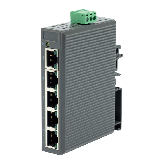
Overview The IESH-MB205-R switches are entry-level 5- port Ethernet switches that provide a cost-effective solution for your industrial Ethernet connection. You could choose either a DC power input from 12 to 48 V or AC power input from 18 to 30 V. These switches can operate from -10 to 60 C, and the rugged hardware design makes the IESH-MB205-R switches perfect for ensuring that your Ethernet equipment can be used for demanding industrial applications. - Page 3 Panel Layout of the IESH-MB205-R Series 1. Heat dissipation orifices 2. Terminal block for power input and grounding 3. Misumi logo 4. Power input LED 5. 10/100BaseT(X) Port 6. TP port’s 100 Mbps LED 7. TP port’s 10 Mbps LED 8.
-
Page 4: Mounting Dimensions
Mounting Dimensions - 4 -... -
Page 5: Din-Rail Mounting
DIN-Rail Mounting The plastic DIN-Rail attachment plate should already be fixed to the rear panel of the EDS when you take it out of the box. If you need to reattach the DIN-Rail attachment plate, make sure the DIN-Rail kit is situated towards the top, as shown in the figures below. -
Page 6: Grounding The Etherdevice Switch
You should also pay attention to the following points: Use separate paths to route wiring for power and devices. If power wiring and device wiring paths must cross, make sure the wires are perpendicular at the intersection point. NOTE: Do not run signal or communications wiring and power wiring in ... -
Page 7: Wiring The Power Inputs
Wiring the Power Inputs The two left-most contacts of the 3-contact terminal block connector on the top panel are used for the DC and AC inputs. Top and front views of one of the terminal block connectors are shown here. STEP 1: Insert the negative/positive DC wires into the V-/V+ terminals. -
Page 8: Communication Connections
Communication Connections The IESH-MB205-R has five10/100BaseT(X) Ethernet ports. 10/100BaseT(X) Ethernet Port Connection The 10/100BaseT(X) ports located on the switch’s front panel are used to connect to Ethernet-enabled devices. Below we show pinouts for both MDI (NIC-type) ports and MDI-X (HUB/Switch-type) ports, and also show cable wiring diagrams for straight-through and cross-over Ethernet cables. -
Page 9: Led Indicators
LED Indicators The front panel of the Switch contains several LED indicators. The function of each LED is described in the table below. Color State Description Power is being supplied to the power input. AMBER Power is not being supplied to the power input. -
Page 10: Switching And Address Learning
Switching and Address Learning The EtherDevice switch has an address table that can hold up to 1K node addresses, making it suitable for use with large networks. The address tables are self-learning, so that as nodes are added or removed, or moved from one segment to another, the switch automatically adds new node locations to the tables. - Page 11 EN61000-4-3 (RS) , level 3 EN61000-4-4 (EFT) , level 3 EN61000-4-5 (Surge) , level 3 EN61000-4-6 (CS) , level 3 Shock IEC 60068-2-27 Freefall IEC 60068-2-32 Vibration IEC 60068-2-6 Applier Misumi Korea Corp. Device Name Ethernet switch Manufacturer Moxa, Inc. - 11 -...
- Page 12 概要 IESH-MB205-R シリーズの MISUMI EtherDevice™ スイッチはエントリ・レベルの 5 ポート・イーサネット・スイッチで、産業用イーサネット接続のための費用対効果に優 れたソリューションを提供します。 IESH-MB205-R では、12~48 V の DC 電源入力または 18~30V の AC 電源入 力のいずれかを選択できます。IESH-MB205-R シリーズは-10℃から 60℃の稼動 時温度に対応し、堅牢なハードウェア設計を採用しているので、要求の多い産業 条件でもイーサネット装置を確実に使用できます。 本書では、MISUMI の EtherDevice スイッチを略して EDS と表記しま メモ す。すなわち、 EDS = MISUMI EtherDevice スイッチ 梱包品確認リスト MISUMI IESH-MB205-R には以下のアイテムが同梱されています。不足しているも...
- Page 13 IESH-MB205-R シリーズのパネル・レイアウト 9. 散熱口 10. 電源入力およびアース用端子台 11. MISUMI のロゴ 12. 電源入力 LED 13. 10/100BaseT(X) ポート 14. TP ポートの 100 Mbps LED 15. TP ポートの 10 Mbps LED 16. DIN レール・キット - 13 -...
- Page 14 取り付け寸法 側面 前面 背面 単位: mm DIN レール・マウント EDS をボックスから取り出すと、リア・パネルにプラスチックの DIN レール装着用プレー トが固定されています。DIN レール・キットを再装着する必要がある場合は、以下の 図ように、必ず DIN レール・キットを上にして装着してください。 ステップ 1: ステップ 2: DIN レールの上部をスロットに挿入しま 下図のように、DIN レール装着ユニットを す。 所定の場所にしっかり取り付けます。 DINレール DINレール - 14 -...
- Page 15 MISUMI IESH-MB205-RのDINレール を取り外すには、マイナスのドライバを IESH-MB205-Rの下のDINレール・キッ トに水平に挿入して引き上げるようにし ます。 DINレール 配線要件 安全第一! MISUMI EtherDevice スイッチのインストールまたは配線の前に電 注意 源コードを必ず外してください。 各電線および共通線の最大許容電流量を計算してください。各 回線容量の最大共許容電流を規定するすべての電気法規を 厳守してください。 電流が最大定格を超えると、配線が過熱して、装置に深刻な 損傷を与える原因となります。 以下の事項にも注意を払ってください: • 電源とデバイスの回線は分離してください。電線とデバイス線を交差させる必要 がある場合は、2 本の回線を必ず直交させてください。 • メモ: 同じ電導管に信号線または通信線と電線を混在させないでください。干 渉を避けるため、信号特性の異なる回線は分離してください。 • 回線を通して送信される信号の種類により、どの回線を分離するかを決定でき ます。通常、同様の電気特性を共有する回線は結束されます。 • 入力線と出力線は分離してください。 • 必要なら、システムのすべてのデバイスの配線に表示を付けておくように強く推奨 します。 - 15 -...
- Page 16 MISUMI EtherDevice スイッチの接地 接地と回線のルーティングは電磁干渉 上面 (EMI)によるノイズを制限するのに役立ち ます。デバイスを接続する前に、3 接点端 子台の右端を接地してください。 前面 この製品は金属パネルなどの接地に優れた搭載面に取り付けるよ うに設計されています。 電源入力の配線 EDS の上部パネルの 3 接点端子台コネクタの左端の 2 接点は EDS の DC または AC 入力に使用されます。端子台コネクタの 1 つの上面および前面は以下の図の 通りです。 ステップ 1: マイナス/プラスの DC 配線を V-/V+端子 に挿入します 上面 ステップ 2: DC ケーブルが緩まないように、小型のマイ...
- Page 17 通信接続 IESH-MB205-R は 5 基の 10/100BaseT(X) イーサネット・ポートを搭載していま す。 10/100BaseT(X) イーサネット・ポートの接続 EDS のフロント・パネル上の 10/100BaseT(X) ポートはイーサネット対応デバイスの 接続に使用されます。 以下は MDI(NIC 型)ポートと MDI-X(ハブ/スイッチ型)ポートの両方のピンアウトお よびストレートとクロス・オーバー・イーサネット・ケーブルの配線図です。 RJ45(8 ピン、MDI)ポートのピンアウト RJ45(8 ピン、MDI-X)ポートのピンアウト RJ45 (8 ピン)-RJ45 (8 ピン) ストレート・ケーブルの配線 RJ45 (8 ピン)-RJ45 (8 ピン) クロス・オーバー・ケーブルの配線 - 17 -...
- Page 18 ない 自動 MDI/MDI-X 接続 自動 MDI/MDI-X 機能を使えば、接続に使用されているイーサネット・ケーブルの種 類を気にせずに、MISUMI EtherDevice スイッチの 10/100BaseTX ポートをあらゆる 種類のイーサネット・デバイスに接続できます。したがって、ストレート・ケーブルやクロ ス・オーバー・ケーブルを使って EDS をイーサネット・デバイスに接続できます。 デュアル・スピード機能とスイッチング MISUMI EtherDevice スイッチの 10/100 Mbps スイッチド RJ45 ポートは両者が対 応している最大データ通信速度で自動ネゴシエートします。MISUMI EtherDevice スイッチの全製品はインストールおよびメンテナンス時にソフトウェア設定が不要な Plug & Play デバイスです。スイッチド RJ45 ポートの半/全二重モードはユーザーに 従属しており、接続デバイスが対応する通信測度により、(自動ネゴシエーション で)全二重または半二重に変更されます。 スイッチング、フィルタリング、フォワーディング パケットがスイッチド・ポートの 1 つに到達するたびに、パケットをフィルタリングするか、...
- Page 19 ・ラーニングに対応しているので、ノードが追加されたり、削除されたり、1 つのセグメ ントから他のセグメントに移動したりすると、MISUMI EtherDevice スイッチはノード 場所を自動的に更新します。アドレス・エージングのアルゴリズムにより、より新しいア ドレスや使用頻度の高いアドレスは使用頻度の低いアドレスを書き換えます。アド レス・バッファをリセットするには、本体の電源を入れ直してください。 自動ネゴシエーションと速度センシング MISUMI EtherDevice スイッチの RJ45 イーサネット・ポートはすべて IEEE 802.3u 規 格に従った動作で 10BaseT モードと 100BaseTX モードの速度の自動ネゴシエーシ ョンに対応しています。したがって、ノードの一部は他のノードが 100 Mbps で動作し ている時に、10 Mbps で同時に動作できます。 自動ネゴシエーションは RJ45 ケーブルが接続されており、LINK がオンになっている 場合に可能となります。MISUMI EtherDevice スイッチは 10 Mbps または 100 Mbps の通信速度を使用して同機能に対応していることを主張し、ケーブルの他端のデバ...
- Page 20 FCC Part 15, CISPR (EN55022) class A EN61000-4-2 (ESD), EN61000-4-3 (RS), EN61000-4-4 (EFT), EN61000-4-5 (Surge), EN61000-4-6 (CS), 衝撃 IEC 60068-2-27 自由落下 IEC 60068-2-32 振動 IEC 60068-2-6 保証 1 年 Applier Misumi Korea Corp. Device Name Ethernet switch Manufacturer Moxa, Inc - 20 -...
Need help?
Do you have a question about the IESH-MB205-R Series and is the answer not in the manual?
Questions and answers