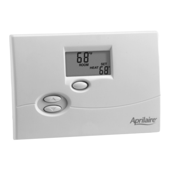
Aprilaire 8346 Installation Manual

Aprilaire 8346 Installation Manual

Aprilaire electronic thermostats installation manual 8346, 8344, 8348, 8363, 8365, 8366
Hide thumbs Also See for 8346:

Advertisement

Electronic
Thermostats
MODEL 8344 HEAT/COOL NON-PROGRAMMABLE
MODEL 8346 HEAT PUMP NON-PROGRAMMABLE
MODEL 8348 HEAT/COOL MULTI-STAGE NON-PROGRAMMABLE
MODEL 8363 HEAT/COOL 5/2 DAY PROGRAMMABLE
MODEL 8365 HEAT PUMP 5/2 DAY PROGRAMMABLE
MODEL 8366 HEAT/COOL MULTI-STAGE 5/2 DAY PROGRAMMABLE

Installation Manual

Advertisement

Table of Contents
loading

Summary of Contents for Aprilaire 8346

  • Page 1: Installation Manual

    Electronic Thermostats MODEL 8344 HEAT/COOL NON-PROGRAMMABLE MODEL 8346 HEAT PUMP NON-PROGRAMMABLE MODEL 8348 HEAT/COOL MULTI-STAGE NON-PROGRAMMABLE MODEL 8363 HEAT/COOL 5/2 DAY PROGRAMMABLE MODEL 8365 HEAT PUMP 5/2 DAY PROGRAMMABLE MODEL 8366 HEAT/COOL MULTI-STAGE 5/2 DAY PROGRAMMABLE Installation Manual...
  • Page 2: Specifications

    RH and W for Models 8344, 8348, 8363 and 8366, and between R and W2 for Models 8346 and 8365. This device is intended to prevent freezing of water pipes should battery replacement be neglected.
  • Page 3 THERMOSTAT INSTALLATION INSTRUCTIONS Step1. Choose a location to mount the thermostat • Approximately 5 feet off the floor (refer to local codes for compliance with the Americans with Disabilities Act). • On an interior wall where the temperature is most representative of the zone being controlled by the thermostat.
  • Page 4 Step 3. Mount the thermostat on the wall There are two sets of mounting holes – one set for use when mounting to a junction box, another set for direct wall mounting. IMPORTANT! TURN OFF POWER AT THE HVAC EQUIPMENT BEFORE PROCEEDING WITH THERMOSTAT INSTALLATION! Mounting the thermostat directly to the wall (without junction box) 1.
  • Page 5 Mounting the thermostat to a junction box 1. Install the top j-box screw (not included), until the head is approximately 1/8” from the surface of the wall. 2. Slide the thermostat on to the top screw. 3. Install the bottom screw (not included) to finish the installation. Mounting the Thermostat to a Junction Box Step 4.
  • Page 6 Set the O/B reversing valve jumper in the proper position (Models 8346 and 8365 only) The thermostat comes with an O/B terminal which can be configured to be an ‘O’ terminal (for most heat pumps) or to be a ‘B’ terminal. Configure as an ‘O’...
  • Page 7: Wire The Thermostat

    Diagram 1 – Model 8344 or 8363 Thermostat Wiring FURNACE STAGE HEAT 1ST STAGE COOL RELAY COOLING EQUIPMENT COOL APRILAIRE MODEL 8344 OR 8363 THERMOSTAT ELEC AUTO HI opens at 100°F±9°F LO closes at 41°F±9°F...
  • Page 8 Diagram 2 – Model 8348 or 8366 Thermostat Wiring HEAT/BLOWER EQUIPMENT STAGE HEAT 2ND STAGE COOL STAGE HEAT 1ST STAGE COOL RELAY COOLING EQUIPMENT COOL COOL APRILAIRE MODEL 8348 OR 8366 THERMOSTAT ELEC AUTO HI opens at 100°F±9°F LO closes at 41°F±9°F...
  • Page 9: Model 8346/8365 Thermostat Wiring

    Diagram 3 – Model 8346 or 8365 Thermostat Wiring HEAT/BLOWER EQUIPMENT 1ST STAGE COMPRESSOR AUX. HEAT RELAY Step 6. Install supplied batteries Install two new AA alkaline batteries (included). Do not mix old and new batteries Step 7. Reassemble the thermostat No tools required –...
  • Page 10: Perform Check-Out

    GAS/ELEC switch on the thermostat is set correctly (see Step 4, MODELS 8344, 8348, 8363 & 8366 ONLY). MODELS 8346 & 8365 – If cold air is coming out of the registers, the reversing valve terminal may need to be configured – see Step 4.
  • Page 11 9. Return the Mode switch to the Off position to stop the cool call. MODELS 8346 & 8365 ONLY 10. Slide the Mode switch to the E-Heat position. 11. Use the ADJUST – Up button to raise the temperature 2°-3° above the current room temperature.
  • Page 12 Step 9. Set up temperature scale, differential, offset and Water Panel/filter change indicators 1. Slide the Mode switch to the Off position. 2. Press and hold both the ADJUST – Up and Down buttons until “ROOM” and “OFF” are no longer displayed. 3.
  • Page 13 Change value is not set to “OFF”. Use the ADJUST – Up or ADJUST – Down button to set this value to “1” if the home has an Aprilaire Model 400 whole house humidifier. The Water Panel in the Model 400 should be changed twice per season and this feature will cause the Water Panel Change Alert to appear on the display 90 days after the first alert.
  • Page 14 (pleated) media type filters. TABLE 1 lists general recommendations, refer to manufacturer literature for recommendations on the filter in your particular application. Set to 12 if the media is original Aprilaire High Efficiency Air Cleaner media. Set the value to “OFF” to disable this feature.
  • Page 15 10. Weekend Events – Use this feature to set the number of events for the weekend program. The default value is 4 events (The E setting), which will result in the “LEAVE” and “RETURN” events to be used during programmed operation. If the owners schedule is such that the home or building is generally occupied during the weekends, switch to 2 events on the weekend.
  • Page 16 Press the CURRENT TIME button to enter the minutes value and access the “day of the week” value. Use the ADJUST – Up and ADJUST – Down buttons to set the current day of the week. CURRENT TIME [ Advance Time ] Press the CURRENT TIME button again to finish.

This manual is also suitable for:

83448348836383658366

Table of Contents