Panasonic CS-ME7NKE Technical & Service Manual
Dc inverter multi-system air conditioner
Hide thumbs
Also See for CS-ME7NKE:
- Operating instructions manual (128 pages) ,
- Technical & service manual (186 pages) ,
- Operating instructions manual (20 pages)
Table of Contents
Advertisement
Available languages
Available languages
Quick Links
TECHNICAL & SERVICE MANUAL
INDOOR UNIT :
DC INVERTER MULTI-SYSTEM AIR CONDITIONER
CS-ME7NKE
CS-ME9NKE
CS-ME12NKE
RoHS
This product does not contain any hazardous substances prohibited by the RoHS Directive.
•
WARNING
• You are requested to use RoHS compliant parts for maintenance or repair.
• You are requested to use lead-free solder.
CS-ME7NKE
CS-ME9NKE
CS-ME12NKE
CS-ME18NKE
CS-ME24NKE
Capacity
Indoor Model No.
2.20 kW
CS-ME7NKE-Y
2.65 kW
CS-ME9NKE-Y
3.50 kW
CS-ME12NKE-Y
5.15 kW
CS-ME18NKE-Y
7.10 kW
CS-ME24NKE-Y
Wall Mounted Type Indoor Unit
Applicable Multi-Outdoor Units >
<
CU-5E34NBE
F-GAS REGULATION (EC) No 842 / 2006
Do not vent R410A into atmosphere : R410A is a fluorinated greenhouse gas,
covered by Kyoto Protocol, with a Global Warming Potential (GWP) = 1975.
Product Code No.
1 852 362 22
1 852 362 23
1 852 362 24
1 852 362 25
1 852 362 26
CS-ME18NKE
CS-ME24NKE
(5-room multi unit)
SM
700884
REFERENCE NO.
Advertisement
Chapters
Table of Contents
Troubleshooting

Related Manuals for Panasonic CS-ME7NKE


Summary of Contents for Panasonic CS-ME7NKE
- Page 1 TECHNICAL & SERVICE MANUAL INDOOR UNIT : CS-ME7NKE CS-ME9NKE CS-ME12NKE CS-ME18NKE CS-ME24NKE DC INVERTER MULTI-SYSTEM AIR CONDITIONER Capacity Indoor Model No. Product Code No. 2.20 kW CS-ME7NKE-Y 1 852 362 22 2.65 kW CS-ME9NKE-Y 1 852 362 23 3.50 kW...
- Page 2 Important! When Transporting Please Read Before Starting Be careful when picking up and moving the indoor and outdoor units. Get a partner to help, and bend your knees This air conditioning system meets strict safety and when lifting to reduce strain on your back. Sharp edges or operating standards.
-
Page 3: Table Of Contents
8-4. Trouble Diagnosis of Fan Motor ................... 8-5. Noise Malfunction and Electromagnetic Interference ..............................APPENDIX A Operating Instructions (CS-ME7NKE, CS-ME9NKE, CS-ME12NKE) ................... APPENDIX B Operating Instructions (CS-ME18NKE, CS-ME24NKE) APPENDIX C INSTALLATION INSTRUCTIONS ................( When combined with CU-5E34NBE ) -
Page 4: Applicable Multi-Outdoor Units
APPLICABLE MULTI-OUTDOOR UNITS Multi-Outdoor Unit 5-Room CU-5E34NBE Indoor Unit CS-ME7NKE CS-ME9NKE CS-ME12NKE CS-ME18NKE CS-ME24NKE... -
Page 5: Operating Range
1. OPERATING RANGE Outdoor Unit : CU-5E34NBE Indoor Unit : CS-ME7NKE, CS-ME9NKE, CS-ME12NKE CS-ME18NKE, CS-ME24NKE Temperature Indoor Air Intake Temp. Outdoor Air Intake Temp. Maximum 32 °C DB / 23 °C WB 43 °C DB Cooling – 10 °C DB Minimum 19 °C DB / 14 °C WB... -
Page 6: Specifications
2. SPECIFICATIONS 2-1. Unit Specifications CS-ME7NKE Indoor Unit Type Wall Mounted Type Indoor Unit Power Source 220 to 240V Single-Phase 50Hz Voltage Rating 230V Performance Cooling Heating Capacity BTU/h 7,500 8,500 Air Circulation (High) Moisture Removal (High) Liters/h Electrical Rating... - Page 7 CS-ME9NKE Indoor Unit Type Wall Mounted Type Indoor Unit Power Source 220 to 240V Single-Phase 50Hz Voltage Rating 230V Performance Cooling Heating Capacity 2.65 BTU/h 9,000 12,300 Air Circulation (High) Moisture Removal (High) Liters/h Electrical Rating Cooling Heating Available Voltage Range 198 to 264 Running Amperes 0.21...
- Page 8 CS-ME12NKE Indoor Unit Type Wall Mounted Type Indoor Unit Power Source 220 to 240V Single-Phase 50Hz Voltage Rating 230V Performance Cooling Heating Capacity BTU/h 11,900 14,300 Air Circulation (High) Moisture Removal (High) Liters/h Electrical Rating Cooling Heating Available Voltage Range 198 to 264 Running Amperes 0.23...
- Page 9 CS-ME18NKE Indoor Unit Type Wall Mounted Type Indoor Unit Power Source 220 to 240V Single-Phase 50Hz Voltage Rating 230V Performance Cooling Heating Capacity 5.15 BTU/h 17,600 20,500 Air Circulation (High) Moisture Removal (High) Liters/h Electrical Rating Cooling Heating Available Voltage Range 198 to 264 Running Amperes 0.33...
- Page 10 CS-ME24NKE Indoor Unit Type Wall Mounted Type Indoor Unit Power Source 220 to 240V Single-Phase 50Hz Voltage Rating 230V Performance Cooling Heating Capacity BTU/h 24,200 29,000 Air Circulation (High) Moisture Removal (High) Liters/h Electrical Rating Cooling Heating Available Voltage Range 198 to 264 Running Amperes 0.34...
-
Page 11: Major Component Specifications
2-2. Major Component Specifications 2-2-1. Indoor Unit CS-ME7NKE Indoor Unit Control PCB Part No. CB-CS-ME7NKE Controls Microprocessor Control Circuit Fuse 250V 3.15A Type Cross-Flow Q'ty ... Dia. and Length 1 ... D94 / L634 Fan Motor Type DC Motor Model ... Q'ty SIC-41CVJ-D847-4 ... - Page 12 CS-ME9NKE Indoor Unit Control PCB Part No. CB-CS-ME9NKE Controls Microprocessor Control Circuit Fuse 250V 3.15A Type Cross-Flow Q'ty ... Dia. and Length 1 ... D94 / L634 Fan Motor Type DC Motor Model ... Q'ty SIC-41CVJ-D847-4 ... 1 No. of Poles Rough Measure RPM (Cool / Heat) 1,100 / 1,100 Nominal Output...
- Page 13 CS-ME12NKE Indoor Unit Control PCB Part No. CB-CS-ME12NKE Controls Microprocessor Control Circuit Fuse 250V 3.15A Type Cross-Flow Q'ty ... Dia. and Length 1 ... D94 / L634 Fan Motor Type DC Motor Model ... Q'ty SIC-41CVJ-D847-4 ... 1 No. of Poles Rough Measure RPM (Cool / Heat) 1,150 / 1,150 Nominal Output...
- Page 14 CS-ME18NKE Indoor Unit Control PCB Part No. CB-CS-ME18NKE Controls Microprocessor Control Circuit Fuse 250V 3.15A Type Cross-Flow Q'ty ... Dia. and Length 1 ... D94 / L845 Fan Motor Type DC Motor Model ... Q'ty SIC-41CVJ-D847-3 ... 1 No. of Poles Rough Measure RPM (Cool / Heat) 1,200 / 1,200 Nominal Output...
- Page 15 Indoor Unit CS-ME24NKE Control PCB Part No. CB-CS-ME24NKE Controls Microprocessor Control Circuit Fuse 250V 3.15A Type Cross-Flow Q'ty ... Dia. and Length 1 ... D94 / L845 Fan Motor Type DC Motor Model ... Q'ty SIC-41CVJ-D847-3 ... 1 No. of Poles Rough Measure RPM (Cool / Heat) 1,250 / 1,250 Nominal Output...
-
Page 16: Other Component Specifications
2-3. Other Component Specifications Quantity of Sensor Model No. Sensor Name of sensor CS-ME7NKE CS-ME9NKE CS-ME12NKE CS-ME18NKE CS-ME24NKE KTEC-35-S139-1 Indoor air temp sensor (1FA4V2E056200) Temperature (°C) Quantity of Sensor Model No. Sensor Name of sensor CS-ME7NKE CS-ME9NKE CS-ME12NKE CS-ME18NKE CS-ME24NKE... -
Page 17: Dimensional Data
3. DIMENSIONAL DATA Indoor Unit CS-ME7NKE CS-ME9NKE CS-ME12NKE Unit: mm (852-0-0010-15500-0) - Page 18 CS-ME18NKE Indoor Unit CS-ME24NKE Unit: mm (852-0-0010-16200-0)
-
Page 19: Refrigerant Flow Diagram
4. REFRIGERANT FLOW DIAGRAM 4-1. Refrigerant Flow Diagram Indoor Unit CS-ME7NKE CS-ME9NKE CS-ME12NKE Indoor unit O.D. 9.52 mm (3/8") Indoor heat exchanger O.D. 6.35 mm (1/4") Cooling cycle Heating cycle Indoor Unit CS-ME18NKE Indoor unit O.D. 12.7 mm (1/2") Indoor heat exchanger O.D. -
Page 20: Performance Data
5. PERFORMANCE DATA 5-1. Air Throw Distance Charts CS-ME7NKE Indoor Unit Cooling Room air temp. : 27 °C Fan speed High Horizontal distance (m) : Flap angle 0°, : Axis air velocity 0° : Flap angle 30°, : Axis air velocity 30°... - Page 21 Indoor Unit CS-ME9NKE Cooling Room air temp. : 27 °C Fan speed High Horizontal distance (m) : Flap angle 0°, : Axis air velocity 0° : Flap angle 30°, : Axis air velocity 30° Heating Room air temp. : 20 °C Fan speed High Horizontal distance (m)
- Page 22 Indoor Unit CS-ME12NKE Cooling Room air temp. : 27 °C Fan speed High Horizontal distance (m) : Flap angle 0°, : Axis air velocity 0° : Flap angle 30°, : Axis air velocity 30° Heating Room air temp. : 20 °C Fan speed High Horizontal distance (m)
-
Page 23: Flap Angle
CS-ME18NKE Indoor Unit Cooling Room air temp. : 27 °C Fan speed High Horizontal distance (m) : Flap angle 0°, : Axis air velocity 0° : Flap angle 30°, : Axis air velocity 30° Heating Room air temp. : 20 °C Fan speed High Horizontal distance (m) -
Page 24: Axis Air Velocity
Indoor Unit CS-ME24NKE Cooling Room air temp. : 27 °C Fan speed High Horizontal distance (m) : Flap angle 0°, : Axis air velocity 0° : Flap angle 30°, : Axis air velocity 30° Heating Room air temp. : 20 °C Fan speed High Horizontal distance (m) -
Page 25: Electrical Data
6. ELECTRICAL DATA 6-1. Electric Wiring Diagrams Indoor Unit CS-ME7NKE CS-ME9NKE CS-ME12NKE To avoid electrical shock hazard, be sure to WARNING disconnect power before checking, servicing and/or cleaning any electrical parts. GRN/YEL FERRITE CORE TERMINAL BASE EVAPORATOR PL MTG FLAP MOTOR... - Page 26 CS-ME18NKE Indoor Unit CS-ME24NKE To avoid electrical shock hazard, be sure to WARNING disconnect power before checking, servicing and/or cleaning any electrical parts. GRN/YEL TERMINAL BASE EVAPORATOR PL MTG CONNECTOR FLAP FLAP 5P (WHT) LAMP 10P (WHT) FLAP MOTOR CONTROLLER ROOM THERMISTOR COIL...
-
Page 27: Functions
7. FUNCTIONS 7-1. Operation Functions Emergency operation SENSOR DRY Emergency operation is available when the remote During DRY operation, the system adjusts the room temperature and fan speed according to the conditions in the controller malfunctions, has been lost, or otherwise room, in order to maintain a comfortable room environment. -
Page 28: Night Setback
HIGH POWER NIGHT SETBACK This function acts to raise the power but keeps the AC system in • When NIGHT SETBACK operation is set, the temperature and the same operating mode. fan speed settings will be adjusted automatically to allow This function is set with the HIGH POWER button on the remote comfortable sleep. -
Page 29: Protective Functions
7-2. Protective Functions Overload prevention during heating Cold-air prevention during heating During HEAT operation, the temperature of the indoor heat During heating, the fan speed is set to "LL" (very low) or stopped. exchanger is used to control the frequency and lessen the load As the temperature of the indoor heat exchanger rises, the fan on the compressor before the protective device is activated. -
Page 30: Troubleshooting (Before Calling For Service)
8. TROUBLESHOOTING (BEFORE CALLING FOR SERVICE) 8-1. Precautions before Performing Inspection or Repair After checking the self-diagnostics monitor, turn the power OFF before starting inspection or repair. High-capacity electrolytic capacitors are used inside the outdoor unit controller (inverter). They retain an electrical charge (charging voltage DC 310V) even after the power is turned OFF, and some time is required for the charge to dissipate. -
Page 31: Operation Lamp
(1) Self-diagnostics Lamps TIMER lamp OPERATION lamp • Since the indications cover various units, the corresponding parts listed below may not be present in some models..OFF ..Blinking ..Illuminated INDICATION ON INDOOR UNIT TIMER OPERATION DIAGNOSIS CONTENTS POSSIBLE MALFUNCTION CODE •... -
Page 32: Checking The Indoor And Outdoor Units
(2) If the self-diagnostics function fails to operate • No indicators illuminate and the Check the indoor unit. indoor fan does not rotate. • Check the power voltage. Blown Is the fuse blown? Normal Replace the circuit board or the fuse. Replace the controller. -
Page 33: Trouble Diagnosis Of Fan Motor
8-4. Trouble Diagnosis of Fan Motor 8-4-1. Indoor Fan Motor This indoor DC fan motor contains an internal control PCB. Therefore, it is not possible to measure the coil resistance, and the following procedure should be used to check the motor. To perform diagnosis, operate the unit in cooling mode with indoor fan speed "High". -
Page 34: Noise Malfunction And Electromagnetic Interference
8-5. Noise Malfunction and Electromagnetic Interference An inverter A/C operates using pulse signal control and high frequencies. Therefore, it is susceptible to the effects of external noise, and is likely to cause electromagnetic interference with nearby wireless devices. A noise filter is installed for ordinary use, preventing these problems. However, depending on the installation conditions, these effects may still occur. -
Page 36: Appendix A Operating Instructions
APPENDIX A Operating Instructions CS-ME7NKE CS-ME9NKE CS-ME12NKE (852-6-4181-223-00-0) -
Page 37: Appendix B Operating Instructions
Antes de utilizar o aparelho, leia completamente este manual de instruções e guarde-o para futuras referências. EΛΛΗΝΙΚΆ 110 ~ 126 Πριν θέσετε τη μονάδα σε λειτουργία, διαβάστε πολύ καλά αυτές τις οδηγίες χρήσης και διατηρήστε τις για μελλοντική αναφορά. © Panasonic Corporation 2012 Unauthorized copying and distribution is a violation of law. 85264181223000 CV6233187747... - Page 38 FEATURES This air conditioner is an inverter type unit that automatically adjusts capability as appropriate. Details on these functions are provided below; refer to these descriptions when using the air conditioner. • Microprocessor Controlled Operation • Hot Start Heating System The interior compartment of the remote controller Right from the start, the air is warm and comfortable.
-
Page 39: Product Information
PRODUCT INFORMATION If you have problems or questions concerning your Air Conditioner, you will need the following information. Model and serial numbers are on the nameplate on the bottom of the cabinet. Model No. _______________________________________________________________________ Serial No. ________________________________________________________________________ Date of purchase __________________________________________________________________ Dealer’s address __________________________________________________________________ Phone number ____________________________________________________________________ SAFETY PRECAUTIONS... -
Page 40: Safety Instructions
SAFETY INSTRUCTIONS • Read these Operating Instructions carefully before using this air conditioner. If you still have any difficulties or problems, consult your dealer for help. • This air conditioner is designed to give you comfortable room conditions. Use this only for its intended purpose as described in these Operating Instructions. -
Page 41: Information
• The compressor may occasionally stop during thunderstorms. NOTICE This is not a mechanical failure. The unit automatically recovers after a few minutes. • The English text is the original instructions. Other languages are translation of the original instructions. Stop using the product when any abnormality/failure occurs and disconnect the power plug. -
Page 42: Names Of Parts
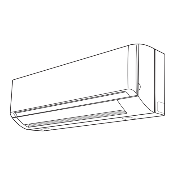
NAMES OF PARTS UNIT DISPLAY AND OPERATION BUTTON Air Intakes INDOOR UNIT INDOOR UNIT TIMER lamp OPERATION lamp Air Outlet Remote Controller OPERATION button REMOTE (ON/OFF ) CONTROL receiver Drain Hose Refrigerant Tubes IMPORTANT OUTDOOR UNIT Avoid using radio equipment such as mobile phone near (within 1 m) the remote control receiver. -
Page 43: Flap Angle
REMOTE CONTROLLER (DISPLAY) Displayed when transmitting data Displayed when indoor unit sensor is in use Displayed when setting temperature Displayed when temperature is shown Displayed when setting timer Displayed when the time display is set to 12-hour time. Symbols (1) Operation mode (4) Timer AUTO ........ - Page 44 REMOTE CONTROLLER Transmitter When you press the buttons on the remote controller, the mark appears in the display to transmit the setting changes to the receiver in the air conditioner. Display Information on the operating conditions is displayed while the remote controller is switched on.
- Page 45 Sensor A temperature sensor inside the remote controller senses the room temperature. ON/OFF operation button This button is for turning the air conditioner on and off. 1 HR. TIMER button (1-HOUR OFF TIMER) : When you press this button, regardless of whether the unit is operating or stopping, the unit operates for one hour and then shuts down.
-
Page 46: Using The Remote Controller
USING THE REMOTE CONTROLLER HOW TO INSTALL BATTERIES HOW TO USE THE REMOTE CONTROLLER When using the remote controller, always point the unit’s transmitter head directly at the air conditioner’s receiver. Air Conditioner (Indoor unit) Receiver Remote Controller (Transmitter head) ACL button REMOTE CONTROLLER INSTALLATION POSITION... -
Page 47: Operation With The Remote Controller
OPERATION WITH THE REMOTE CONTROLLER 1. Automatic Operation 2. Manual Operation The air conditioner calculates the difference between the thermostat setting and room temperature, and automatically selects ‘‘COOL’’ or ‘‘HEAT’’ mode as appropriate. Then, the air conditioner continuously operates under the mode selected at initial operation. -
Page 48: Adjusting The Fan Speed
3. Adjusting the Fan Speed B. In Heating Mode: ( A. Automatic fan speed When the night setback mode is selected, the air conditioner Simply set the FAN SPEED selector button to the automatically lowers the temperature setting 2 °C when 30 minutes have passed after the selection was made, and then position. -
Page 49: High Power Mode
SPECIAL REMARKS 6. HIGH POWER Mode ‘‘DRY’’ ( ) Operation How it works? • Once the room temperature reaches the level that was set, the unit’s operation frequency is changed automatically. • During DRY operation, the fan speed automatically runs at lower speed for providing a comfortable breeze. -
Page 50: Setting The Timer
SETTING THE TIMER 3. How to set the ON time (Example) To start operation at 7:10 am. Operation Indication Press the ON TIME setting The timer indication is button once. displayed, and the present ON NOTE time is shown. In the descriptions below, the following settings are used for the temperature and time indicator selector button on the bottom front Press the Advance, Return The timer... -
Page 51: Using The 1-Hour Off Timer
USING THE 1-HOUR OFF TIMER 1. 1-Hour OFF Timer CAUTION When the humidity is high, the vertical vanes should be in the front position during the cooling or dehumidifying operation. If the vertical vanes are positioned all of the way to the right or left, condensation may begin to form around the air vent and drip down. -
Page 52: Operation Without The Remote Controller
OPERATION WITHOUT THE Anti-Mold Filter The anti-mold filter behind the front panel should be checked and REMOTE CONTROLLER cleaned at least once every two weeks. How to remove the anti-mold filter INDOOR UNIT Open the front panel until it is nearly horizontal. Lift the anti-mold filter up slightly and then pull downward to remove the filter from the unit. -
Page 53: Troubleshooting (Before Calling For Service)
How to install the air clean filter Trouble Possible Cause Remedy The air clean filter needs to be installed behind the anti-mold filter. Open the front panel and remove the anti-mold filters, then install Air conditioner does 1. Power failure. 1. -
Page 54: Specifications
SPECIFICATIONS Indoor Unit Model No. CS-ME7NKE CS-ME9NKE CS-ME12NKE Power Source Single-phase, 220-230-240 V, 50 Hz 2.20 2.65 3.50 Cooling Capacity BTU/h 7,500 9,000 11,900 2.50 3.60 4.20 Heating Capacity BTU/h 8,500 12,300 14,300 Sound Power Level dB(A) 51/48/45 52/49/46 54/51/47... - Page 56 CARACTERÍSTICAS Este acondicionador de aire es una unidad de tipo inversor que ajusta automáticamente la capacidad de forma apropiada. A continuación se ofrecen detalles sobre estas funciones; refiérase a estas descripciones cuando utilice el acondicionador de aire. • Funcionamiento controlado por microprocesador •...
-
Page 57: Información Del Producto
INFORMACIÓN DEL PRODUCTO Si tiene preguntas o problemas relacionados con su acondicionador de aire necesitará la siguiente información. Los números de modelo y de serie se encuentran en la placa de características situada en la parte inferior del aparato. N° de modelo ____________________________________________________________________ N°... -
Page 58: Instrucciones De Seguridad
INSTRUCCIONES DE SEGURIDAD • Lea con atención estas instrucciones de funcionamiento antes de utilizar este acondicionador de aire. Si sigue teniendo alguna dificultad o problema, póngase en contacto con su concesionario para que le ayude a solucionarlo. • Este acondicionador de aire ha sido diseñado para proporcionarle un ambiente agradable en su habitación. Utilícelo solamente con la finalidad para la que ha sido diseñado según se describe en estas instrucciones de funcionamiento. -
Page 59: Información
• El compresor puede dejar de funcionar ocasionalmente durante las tormentas. No se trata AVISO de un fallo mecánico. La unidad se recuperará automáticamente al cabo de unos minutos. • El texto en inglés constituye las instrucciones originales. El resto de los idiomas son traducciones de las instrucciones originales. -
Page 60: Nombres De Las Partes
NOMBRES DE LAS VISUALIZADOR DE LA UNIDAD Y PARTES BOTONES DE OPERACIÓN Entrada de aire UNIDAD INTERIOR UNIDAD INTERIOR Lámpara del temporizador (TIMER) Lámpara de funcionamiento (OPERATION) Salida de aire Mando a distancia Botón de operación Receptor del (ON/OFF) mando a distancia Manguera de drenaje IMPORTANTE Evite utilizar equipos de radio tales como un teléfono móvil... - Page 61 MANDO A DISTANCIA (VISUALIZADOR) Presentado cuando se transmiten datos Presentado cuando se utiliza el sensor de la unidad interior Presentado cuando se ajusta la temperatura Presentado cuando se muestra la temperatura Presentado cuando se ajusta el temporizador Se visualiza cuando la visualización de la hora está...
- Page 62 MANDO A DISTANCIA Transmisor Cuando usted pulsa los botones del mando a distancia, la marca aparece en el visualizador para transmitir los cambios de ajuste al receptor del acondicionador de aire. Visualizador La información de las condiciones del funcionamiento se visualiza mientras la alimentación del mando a distancia está...
- Page 63 Sensor Un sensor incorporado en el interior del mando a distancia detecta la temperatura de la sala. Botón de operación de encendido/apagado (ON/OFF) Este botón es para encender y apagar el acondicionador de aire. Botón del temporizador de apagado en 1 hora (1 HR. TIMER) : Cuando pulse este botón, sin tener en cuenta si la unidad está...
-
Page 64: Utilización Del Mando A Distancia
UTILIZACIÓN DEL MANDO A DISTANCIA MODO DE INSTALAR LAS PILAS MODO DE UTILIZAR EL MANDO A DISTANCIA Cuando utilice el mando a distancia, oriente siempre directamente la cabeza del transmisor hacia el receptor del acondicionador de aire. Acondicionador de aire (unidad interior) Receptor (Cabeza del... -
Page 65: Funcionamiento Con El Mando A Distancia
FUNCIONAMIENTO CON EL MANDO A DISTANCIA 1. Funcionamiento automático 2. Funcionamiento manual El acondicionador de aire calcula la diferencia entre el ajuste del termostato y la temperatura de la habitación y cambia automáticamente al modo “COOL” o “HEAT” según sea apropiado. Entonces, el acondicionador de aire funciona continuamente bajo el modo seleccionado en la operación inicial. -
Page 66: Ajuste De La Velocidad Del Ventilador
3. Ajuste de la velocidad del ventilador B. En el modo de calefacción: ( Velocidad del ventilador automática Cuando se selecciona el modo de economización nocturna, el acondicionador de aire disminuye automáticamente la temperatura Ponga simplemente el botón selector FAN SPEED en la en 2 °C a los 30 minutos de haber seleccionado dicho modo, y posición ‘‘... -
Page 67: Modo High Power (Funcionamiento A Alta Potencia)
OBSERVACIONES 6. Modo HIGH POWER (funcionamiento a alta potencia) ESPECIALES Operación ‘‘DRY’’ ( ) (deshumidificación) ¿Cómo funciona? • Una vez que la temperatura de la habitación alcance el nivel que haya sido ajustado, la frecuencia de encendido y apagado de la operación de la unidad cambiará... -
Page 68: Ajuste Del Temporizador
AJUSTE DEL 3. Cómo ajustar la hora de encendido (Ejemplo) Para iniciar la operación a las 7:10 am. TEMPORIZADOR Operación Indicación Presione el botón de ajuste Se visualizará la indicación del de la hora de encendido temporizador , y se (ON TIME) una vez. -
Page 69: Utilización Del Temporizador De Apagado En 1 Hora
UTILIZACIÓN DEL TEMPORIZADOR DE APAGADO EN 1 HORA 1. Temporizador de apagado en 1 hora PRECAUCIÓN Cuando haya mucha humedad, las aspas verticales deberán estar en la posición frontal durante las funciones de enfriamiento o deshumidificación. Si las aspas verticales están posicionadas completamente hacia la derecha o hacia la izquierda, podría comenzar a formarse condensación Este temporizador hace que la unidad funcione durante una... -
Page 70: Funcionamiento Sin El Mando A Distancia
FUNCIONAMIENTO SIN EL Filtro antihongos El filtro antihongos detrás de la rejilla de entrada de aire deberá MANDO A DISTANCIA comprobarse y limpiarse por lo menos una vez cada dos semanas. UNIDAD INTERIOR Modo de retirar el filtro antihongos Abra el panel frontal hasta que esté casi horizontal. Levante el Lámpara de funcionamiento filtro antihongos un poco hacia arriba y luego tire hacia abajo para retirar el filtro de la unidad. -
Page 71: Resolución De Problemas (Antes De Avisar Al Servicio Técnico)
Modo de instalar el filtro de limpieza del aire Avería Causa posible Remedio El filtro de limpieza del aire hay que instalarlo detrás del filtro antihongos. Abra el panel frontal y retire los filtros antihongos, El acondicionador de 1. Corte de 1. -
Page 72: Especificaciones
ESPECIFICACIONES Unidad interior N° de modelo CS-ME7NKE CS-ME9NKE CS-ME12NKE Fuente de alimentación Monofásico, 220-230-240 V, 50 Hz 2,20 2,65 3,50 Capacidad de refrigeración BTU/h 7.500 9.000 11.900 2,50 3,60 4,20 Capacidad de calefacción BTU/h 8.500 12.300 14.300 Nivel de potencia... - Page 74 CARACTÉRISTIQUES Ce climatiseur est un appareil de type inverseur qui règle lui-même sa puissance en fonction des conditions environnantes. Des détails sur ces fonctions sont fournis ci-dessous ; se référer à ces descriptions lors de l’utilisation du climatiseur. • Fonctionnement contrôlé par microprocesseur •...
-
Page 75: Informations Sur Le Produit
INFORMATIONS SUR LE PRODUIT Pour tout problème ou toute question relatifs au climatiseur, il faudra les informations ci-dessous. Les numéros de série et de modèle figurent sur la plaque signalétique placée sur le fond du coffret. N° de modèle _____________________________________________________________________ N°... -
Page 76: Conseils De Sécurité
CONSEILS DE SÉCURITÉ • Lire attentivement ce mode d’emploi avant de faire fonctionner le climatiseur. Si l’on rencontre des difficultés ou des problèmes, consulter son concessionnaire. • Le climatiseur est conçu pour créer un environnement confortable chez soi. Ne l’utiliser qu’aux fins pour lesquelles il a été prévu, en suivant les instructions de ce mode d’emploi. -
Page 77: Informations
• Il se peut que le compresseur s’arrête parfois pendant des orages. Ceci n’est pas NOTIFICATION une panne mécanique. L’appareil redémarre automatiquement après quelques minutes. • Le texte anglais correspond aux instructions d’origine. Les autres langues sont les traductions des instructions d’origine. Arrêter d’utiliser le produit lorsqu’une anomalie/panne se produit et débrancher la prise d’alimentation. -
Page 78: Nom Des Pièces
NOM DES PIÈCES AFFICHEUR DE L’APPAREIL ET BOUTON DE Arrivée d’air ÉLÉMENT INTÉRIEUR FONCTIONNEMENT ÉLÉMENT INTÉRIEUR Voyant de temporisateur (TIMER) Voyant de fonctionnement (OPERATION) Sortie d’air Télécommande Bouton de fonctionnement Récepteur de (ON/OFF) télécommande Tube de vidange Tuyaux de fluide frigorigène IMPORTANT ÉLÉMENT EXTÉRIEUR... - Page 79 TÉLÉCOMMANDE (AFFICHAGE) Affiché lors de la transmission de données Affiché lorsque le capteur de l’élément intérieur est actif Affiché lors du réglage de température Affiché quand la température est indiquée Affiché lors du réglage du temporisateur Affiché uniquement lorsque l’heure est réglée sur l’horloge de 12 heures.
- Page 80 TÉLÉCOMMANDE Émetteur Quand on appuie sur les boutons de la télécommande, le voyant apparaît sur l’afficheur pour signaler la transmission des réglages au récepteur du climatiseur. Afficheur Les informations sur le mode de fonctionnement s’affichent lorsque la télécommande est allumée. Les réglages FLAP (Volet) et FAN SPEED (Vitesse de ventilation) ne sont pas affichés.
- Page 81 Capteur Le capteur de température incorporé à la télécommande détecte la température de la pièce. Bouton de marche/arrêt de fonctionnement (ON/OFF) Ce bouton permet de mettre le climatiseur en marche et de l’arrêter. Bouton de temporisateur 1 heure (1 HR. TIMER) : Qu’il soit en service ou non, quand ce bouton est actionné...
-
Page 82: Utilisation De La Télécommande
UTILISATION DE LA TÉLÉCOMMANDE INSTALLATION DES PILES UTILISATION DE LA TÉLÉCOMMANDE Quand on utilise la télécommande, toujours diriger la tête de l’émetteur droit sur le récepteur du climatiseur. Climatiseur (élément intérieur) Récepteur Télécommande (Tête de l’émetteur) Bouton ACL EMPLACEMENT D’INSTALLATION DE LA TÉLÉCOMMANDE Glisser le couvercle dans le sens indiqué... -
Page 83: Fonctionnement Avec Télécommande
FONCTIONNEMENT AVEC TÉLÉCOMMANDE 1. Fonctionnement automatique 2. Fonctionnement manuel Le climatiseur calcule la différence entre le réglage du thermostat et la température de la pièce, et il sélectionne automatiquement le mode de refroidissement (COOL) ou de chauffage (HEAT) selon le cas. -
Page 84: Réglage De La Vitesse Du Ventilateur
3. Réglage de la vitesse du ventilateur B. En mode de chauffage : ( A. Vitesse automatique du ventilateur Quand le mode d’économie nocturne est sélectionné, le Il suffit de mettre le sélecteur de vitesse du ventilateur climatiseur abaisse automatiquement de 2 °C le réglage de la température quand 30 minutes se sont écoulées après que la (FAN SPEED) sur la position sélection a été... -
Page 85: Mode De Fonctionnement À Haute Puissance (High Power)
REMARQUES SPÉCIALES 6. Mode de fonctionnement à haute puissance (HIGH POWER) Séchage (DRY ( )) Comment agit-il ? • Une fois que la température de la pièce atteint le niveau réglé, la vitesse de fonctionnement de l’appareil est modifiée automatiquement. •... -
Page 86: Réglage Du Temporisateur
RÉGLAGE DU 3. Réglage du moment de mise en marche (Exemple) pour mettre le climatiseur en marche à 7:10 a.m. TEMPORISATEUR Démarche Affichage Appuyer sur le bouton de L’indicateur réglage de l’heure de mise temporisateur apparaît et en marche (ON TIME). l’heure de mise en marche (ON) actuelle est affichée. -
Page 87: Emploi Du Temporisateur 1 Heure
EMPLOI DU TEMPORISATEUR 1 HEURE 1. Temporisateur 1 heure (1 Hour OFF Timer) ATTENTION Lorsque l’humidité est élevée, les ailettes verticales doivent se trouver à la position avant pendant le refroidissement ou le séchage. Si elles sont placées à fond vers la gauche ou la droite, une condensation risque de se produire autour de la Cette fonction fait en sorte que l’appareil fonctionne pendant sortie d’air et de s’égoutter. -
Page 88: Fonctionnement Sans Télécommande
FONCTIONNEMENT SANS Filtre anti-moisissure Le filtre anti-moisissure situé derrière le panneau avant doit être TÉLÉCOMMANDE vérifié et nettoyé au moins une fois toutes les deux semaines. Retrait du filtre anti-moisissure ÉLÉMENT INTÉRIEUR Ouvrir le panneau avant jusqu’à ce qu’il soit presque à l’horizontale. -
Page 89: Dépannage (Avant D'appeler Le Service Après-Vente)
Installation du filtre de nettoyage d’air Panne Cause possible Remède Le filtre de nettoyage d’air doit être installé derrière le filtre anti- Le climatiseur ne 1. Panne de courant. 1. Rétablir moisissure. fonctionne pas du tout. l’alimentation. Ouvrir le panneau avant et retirer les filtres anti-moisissure, puis installer le filtre de nettoyage d’air sur la position indiquée sur 2. - Page 90 CARACTÉRISTIQUES Élément intérieure N° de modèle CS-ME7NKE CS-ME9NKE CS-ME12NKE Source d’alimentation Monophasé, 220-230-240 V, 50 Hz 2,20 2,65 3,50 Capacité de refroidissement BTU/h 7 500 9 000 11 900 2,50 3,60 4,20 Capacité de chauffage BTU/h 8 500 12 300...
- Page 92 MERKMALE Dieses Klimagerät ist ein Invertergerät, das den Betrieb automatisch wie geeignet einstellt. Einzelheiten zu diesen Funktionen finden Sie unten. Beziehen Sie sich auf diese Beschreibungen, wenn Sie das Klimagerät verwenden. • Mikroprozessorgesteuerter Betrieb • Warmstart-Heizsystem Über Bedienungselemente im Innenfach der Dieses System sorgt dafür, dass die nach dem Starten Fernbedienung besteht Zugriff auf verschiedene des Heizbetriebs abgegebene Luft angenehm warm ist,...
-
Page 93: Produkt-Information
PRODUKT-INFORMATION Falls Probleme oder Fragen zu diesem Klimagerät auftreten sollten, die eine Kontaktaufnahme mit dem Kundendienst erforderlich machen, werden die folgenden Angaben benötigt. Die Modell- und die Seriennummer befinden sich auf dem Typenschild an der Unterseite des Gehäuses. Modellnummer _____________________________________________________________________ Seriennummer _____________________________________________________________________ Kaufdatum ________________________________________________________________________ Anschrift des Fachhändlers ___________________________________________________________... -
Page 94: Sicherheitsvorschriften
SICHERHEITSVORSCHRIFTEN • Vor Inbetriebnahme dieses Klimagerätes sollten Sie diese Bedienungsanleitung aufmerksam durchlesen. Falls Sie danach immer noch irgendwelche Schwierigkeiten oder Fragen haben sollten, wenden Sie sich bitte an Ihren Fachhändler. • Dieses Klimagerät ist so konstruiert, dass es für ein angenehmes Raumklima sorgt. Verwenden Sie dieses Gerät nur für seinen beabsichtigten Zweck gemäß... -
Page 95: Informationen
• Es kann vorkommen, dass der Betrieb des Kompressors bei Gewittern unterbrochen HINWEIS wird. Dies ist kein mechanischer Defekt. Das Gerät nimmt nach einigen Minuten automatisch den Betrieb wieder auf. • Bei der englischen Textfassung handelt es sich um das Original. Bei den Anleitungen in anderen Sprachen handelt es sich um Übersetzungen des Originals. -
Page 96: Bezeichnungen Der Teile
BEZEICHNUNGEN DER TEILE ANZEIGEFELD UND BETRIEBSTASTE Lufteinlass INNENEINHEIT INNENEINHEIT Zeitschaltuhrlampe (TIMER) Betriebslampe (OPERATION) Luftauslass Fernbedienung Betriebstaste Fernbedienungsempfänger (ON/OFF) Ablassschlauch WICHTIG Kältemittelleitungen Vermeiden Sie die Verwendung von Funkgeräten, AUSSENEINHEIT beispielsweise von Mobiltelefonen, in der Nähe (innerhalb von 1 m) des Fernbedienungsempfängers. Einige Funkgeräte können zu Funktionsstörungen des Klimagerätes führen. - Page 97 FERNBEDIENUNG (ANZEIGEFELD) Erscheint während der Übertragung von Daten. Erscheint, wenn der Sensor der Inneneinheit verwendet wird. Erscheint beim Einstellen der Temperatur. Erscheint, wenn die Temperatur angezeigt wird. Erscheint beim Einstellen der Zeitschaltuhr. Erscheint, wenn die 12-Stunden-Zeitanzeige verwendet wird. Symbole (1) Betriebsart (4) Zeitschaltuhr AUTO 24-Stunden-Uhr mit...
- Page 98 FERNBEDIENUNG Geber Beim Drücken der Tasten an der Fernbedienung erscheint das Symbol auf dem Anzeigefeld, um zu kennzeichnen, dass die Einstellungsänderungen an den Empfänger im Klimagerät übertragen werden. Anzeigefeld Informationen über den aktuellen Betriebszustand werden angezeigt, während die Fernbedienung eingeschaltet ist. Fall das Gerät ausgeschaltet wird, werden die Klappen- und die Gebläsedrehzahleinstellung nicht angezeigt.
- Page 99 Sensor Ein Temperatursensor in der Fernbedienung erfasst die Raumtemperatur. Betriebstaste (ON/OFF) Diese Taste dient zum Ein- und Ausschalten des Klimagerätes. 1-Stunden-Ausschaltzeitschaltuhr-Taste (1 HR. TIMER) : Nach Drücken dieser Taste arbeitet das Gerät eine Stunde lang und schaltet sich danach aus, wobei es keine Rolle spielt, ob das Gerät beim Betätigen der Taste ein- oder ausgeschaltet ist.
-
Page 100: Gebrauch Der Fernbedienung
GEBRAUCH DER FERNBEDIENUNG EINSETZEN DER BATTERIEN VERWENDUNG DER FERNBEDIENUNG Bei Verwendung der Fernbedienung deren Geberkopf stets direkt auf den Empfänger des Klimageräts richten. Klimagerät (Inneneinheit) Empfänger Fernbedienung (Geberkopf) ACL-Knopf MONTAGEPOSITION DER FERNBEDIENUNG Die Fernbedienung kann wahlweise von einer nicht ortsfesten Den Batteriefachdeckel zum Entfernen in Pfeilrichtung Position aus, oder an einer Wand montiert, bedient werden. -
Page 101: Betrieb Mit Hilfe Der Fernbedienung
BETRIEB MIT HILFE DER FERNBEDIENUNG 1. Automatischer Betrieb 2. Manueller Betrieb Bei Wahl dieser Einstellung errechnet das Klimagerät die Differenz zwischen der Thermostat-Einstellung und der Raumtemperatur und schaltet dementsprechend automatisch auf Kühlen (COOL) oder Heizen (HEAT) um. Stattdessen arbeitet das Klimagerät ständig in der ursprünglich gewählten Betriebsart. -
Page 102: Einstellen Der Gebläsedrehzahl
3. Einstellen der Gebläsedrehzahl B. In der Betriebsart für Heizen: ( A. Automatische Gebläsedrehzahl Nach Wahl der Nachtrückstell-Betriebsart erniedrigt das Einfach die Gebläsedrehzahl-Wahltaste (FAN SPEED) auf Klimagerät die eingestellte Temperatur automatisch um 2 °C, wenn 30 Minuten nach Wahl der Betriebsart verstrichen sind, einstellen. -
Page 103: Hochleistungsbetrieb (High Power)
BESONDERE HINWEISE 6. Hochleistungsbetrieb (HIGH POWER) Entfeuchtungsbetrieb ( ) Funktionsprinzip • Sobald die Raumtemperatur den eingestellten Wert erreicht hat, wird die Betriebsfrequenz des Geräts automatisch geändert. • Während des Entfeuchtungsbetriebs (DRY) wird die Gebläsedrehzahl automatisch auf eine niedrigere Drehzahl eingestellt, um eine bequeme Brise zu erzeugen. •... -
Page 104: Einstellen Der Zeitschaltuhr
EINSTELLEN DER 3. Einstellen der Einschaltzeit ZEITSCHALTUHR (Beispiel) Einschalten des Klimagerätes um 7:10 am Bedienung Anzeige Drücken Sie die Einschaltzeit- Die Zeitschaltuhr-Anzeige Einstellungstaste (ON) einmal. erscheint und zeigt die gegenwärtige Einschaltzeit an. ZUR BEACHTUNG Drücken Sie die Vorlauf- Die Zeitschaltuhr-Anzeige blinkt. -
Page 105: Gebrauch Der 1-Stunden-Ausschaltzeitschaltuhr
GEBRAUCH DER 1-STUNDEN- AUSSCHALTZEITSCHALTUHR 1. 1-Stunden-Ausschaltzeitschaltuhr VORSICHT Bei hoher Luftfeuchtigkeit sollten die vertikalen Luftleitlamellen während des Kühl- oder Entfeuchtungsbetriebs geradeaus nach vorn weisen. Wenn sie bis zum Anschlag nach rechts oder links Diese Funktion dient dazu, das Gerät eine Stunde lang arbeiten zu geschoben sind, kann sich Kondenswasser im Umfeld des lassen und danach automatisch auszuschalten, wobei es keine Rolle Luftauslaßgitters bilden und auf den Boden tropfen. -
Page 106: Betrieb Ohne Fernbedienung
BETRIEB OHNE FERNBEDIENUNG Schimmelverhütungs-Filter Der Schimmelverhütungs-Filter hinter der Frontplatte sollte mindestens alle zwei Wochen überprüft und gereinigt werden. INNENEINHEIT Entfernen des Schimmelverhütungs-Filters Öffnen Sie die Frontplatte, bis sie fast waagerecht ist. Heben Sie Betriebslampe den Schimmelverhütungs-Filter leicht an und ziehen Sie dann den (OPERATION) Filter nach unten, um ihn vom Gerät zu entfernen. -
Page 107: Fehlersuche (Bevor Der Kundendienst Gerufen Wird)
FEHLERSUCHE (BEVOR DER KUNDENDIENST Einsetzen des Reinigungs-Luftfilters Der Reinigungs-Luftfilter muss hinter dem Schimmelverhütungs- GERUFEN WIRD) Filter eingesetzt werden. Öffnen Sie die Frontplatte, entfernen Sie die Schimmelverhütungs-Filter, und setzen Sie dann den Wenn Ihr Klimagerät nicht richtig funktioniert, zuerst die folgenden Reinigungs-Luftfilter an der in der Abbildung gezeigten Position Punkte überprüfen, bevor ein Kundendiensttechniker angefordert ein. -
Page 108: Technische Daten
TECHNISCHE DATEN Innengerät Modellnummer CS-ME7NKE CS-ME9NKE CS-ME12NKE Spannungsquelle Einphasenstrom, 220-230-240 V, 50 Hz 2,20 2,65 3,50 Kühlleistung BTU/h 7.500 9.000 11.900 2,50 3,60 4,20 Heizleistung BTU/h 8.500 12.300 14.300 Schallleistungspegel dB(A) 51/48/45 52/49/46 54/51/47 (H/M/N) Kühlbetrieb Schalldruckpegel dB(A) 33/30/27 34/31/28... - Page 110 CARATTERISTICHE Questo condizionatore d’aria è un’unità di tipo inverter che regola automaticamente la capacità nel modo appropriato. Per maggiori informazioni su tali funzioni, consultate le relative descrizioni sotto riportate e fatevi riferimento per l’uso del condizionatore. • Funzionamento controllato da microprocessore •...
-
Page 111: Informazioni Riguardanti Il Prodotto
INFORMAZIONI RIGUARDANTI IL PRODOTTO In caso di difficoltà o se si hanno dei dubbi riguardo al condizionatore d’aria, sono necessarie le informazioni seguenti. I numeri del modello e di serie si trovano sulla targhetta di identificazione, sulla parte inferiore dell’armadio. No. -
Page 112: Istruzioni Di Sicurezza
ISTRUZIONI DI SICUREZZA • Leggete attentamente questi istruzioni per l’uso prima di usare il condizionatore d’aria. In caso di dubbi o problemi, rivolgersi al proprio rivenditore. • Questo condizionatore d’aria è progettato per rendere confortevoli le condizioni ambientali della vostra stanza. Utilizzarlo soltanto per lo scopo previsto, come descritto in questi istruzioni per l’uso. -
Page 113: Informazioni
• AVVISO Il compressore potrebbe occasionalmente arrestarsi durante i temporali con fulmini. Non si tratta di un guasto meccanico. L’unità riprende automaticamente a funzionare dopo qualche minuto. • Il testo in inglese corrisponde alle istruzioni originali. Le altre lingue sono traduzioni delle istruzioni originali. -
Page 114: Nome Delle Parti
NOME DELLE PARTI DISPLAY E PULSANTE DI FUNZIONAMENTO DELL’UNITÀ Prese d’aria UNITÀ INTERNA UNITÀ INTERNA Spia del timer (TIMER) Spia di funzionamento (OPERATION) Uscita dell’aria Telecomando Pulsante di funzionamento Ricevitore (ON/OFF) telecomando Manicotto di scarico IMPORTANTE Tubi del refrigerante Evitate l’uso di apparecchi radiofonici quali telefoni cellulari UNITÀ... - Page 115 TELECOMANDO (DISPLAY) Visualizzato durante la trasmissione dei dati Visualizzato quando viene usato il sensore dell’unità interna Visualizzato durante l’impostazione della temperatura Visualizzato quando viene visualizzata anche la temperatura Visualizzato durante l’impostazione del timer Visualizzato quando la visualizzazione dell’ora è impostata su 12 ore. Simboli (1) Modalità...
- Page 116 TELECOMANDO Trasmettitore Quando si premono i pulsanti sul telecomando, il segno appare sul display per trasmettere le variazioni di impostazione al ricevitore del condizionatore d’aria. Display Le informazioni sulle condizioni di funzionamento vengono mostrate quando il telecomando è acceso. Se l’unità è spenta, l’impostazione FLAP (deflettore) e l’impostazione FAN SPEED (velocità...
- Page 117 Sensore Il sensore della temperatura, all’interno del telecomando, rileva la temperatura della stanza. Pulsante di accensione/ spegnimento (ON/OFF) Serve ad accendere e spegnere il condizionatore d’aria. Pulsante del timer ad 1 ora (1 HR. TIMER) (Timer di spegnimento ad un’ora) : Premendo questo pulsante, il condizionatore d’aria funziona per un’ora e poi si spegne, indipendentemente dal fatto che sia in funzione o meno al momento della pressione del pulsante.
-
Page 118: Uso Del Telecomando
USO DEL TELECOMANDO INSTALLAZIONE DELLE BATTERIE COME USARE IL TELECOMANDO Usando il telecomando, puntare sempre direttamente la testina trasmettitore dell’unità verso il ricevitore telecomando del condizionatore d’aria. Condizionatore d’aria (unità interna) Ricevitore Telecomando (Testina del trasmettitore) Pulsante ACL POSIZIONE DI INSTALLAZIONE Far scorrere il coperchio nella direzione indicata dalla freccia e TELECOMANDO rimuoverlo. -
Page 119: Funzionamento Con Il Telecomando
FUNZIONAMENTO CON IL TELECOMANDO 1. Funzionamento automatico 2. Funzionamento manuale Il condizionatore d’aria calcola la differenza tra l’impostazione del termostato e la temperatura della stanza e seleziona automaticamente la modalità “COOL” (Raffredamento) o “HEAT” (Riscaldamento) più appropriata. Il condizionatore d’aria funziona poi continuamente nella modalità... -
Page 120: Regolazione Della Velocità Della Ventola
3. Regolazione della velocità della ventola B. Nella modalità di riscaldamento: ( Regolazione automatica della velocità Quando è selezionata la modalità di regolazione notturna, il ventola condizionatore d’aria abbassa automaticamente la temperatura impostata di 2 °C dopo 30 minuti dalla selezione, e ancora di Portare semplicemente il selettore di velocità... -
Page 121: Modalità Alta Potenza (High Power)
OSSERVAZIONI SPECIALI 6. Modalità Alta potenza (HIGH POWER) Deumidificazione ( ) Come funziona? • Una volta che la temperatura della stanza raggiunge il livello impostato, la frequenza di funzionamento del’unità viene cambiata automaticamente. • Durante la deumidificazione, la velocità della ventola funziona automaticamente a bassa velocità... -
Page 122: Impostazione Del Timer
IMPOSTAZIONE DEL TIMER 3. Impostazione dell’ora di accensione (Esempio) Per accendere l’unità alle 7:10 am. Operazione Indicazione Vengono visualizzati l’indicazione Premere una volta il pulsante di impostazione dell’ora di del timer di accensione NOTA accensione (ON TIME). il tempo di accensione (ON time) corrente. -
Page 123: Uso Del Timer Di Spegnimento (Off) A 1 Ora
USO DEL TIMER DI SPEGNIMENTO (OFF) A 1 ORA 1. Timer di spegnimento a 1 ora PRECAUZIONE Quando il livello di umidità è elevato, durante il raffreddamento e la deumidificazione le alette verticali dovrebbero essere diritte, in posizione frontale. Se le alette Questa funzione attiva l’unità... -
Page 124: Funzionamento Senza Il Telecomando
FUNZIONAMENTO SENZA IL Filtro antimuffa Il filtro antimuffa, posto dietro la presa d’aria, va controllato e pulito TELECOMANDO almeno ogni due settimane. Estrazione del filtro antimuffa UNITÀ INTERNA Aprire il pannello anteriore finché non è quasi orizzontale. Sollevare leggermente il filtro antimuffa, e tirarlo poi giù per rimuovere il filtro dall’unità. -
Page 125: Risoluzione Dei Problemi (Prima Di Chiamare L'assistenza Tecnica)
Installazione del filtro dell’aria Problema Causa probabile Rimedio Il filtro dell’aria deve essere installato dietro il filtro antimuffa. Il condizionatore d’aria 1. Si è verificata una 1. Ripristinare la Aprire il pannello anteriore, rimuovere i filtri antimuffa e installare non funziona. mancanza di corrente. -
Page 126: Specifiche
SPECIFICHE Unità interna No. del modello CS-ME7NKE CS-ME9NKE CS-ME12NKE Fonte di alimentazione Monofase, 220-230-240 V, 50 Hz 2,20 2,65 3,50 Capacità di raffreddamento BTU/h 7.500 9.000 11.900 2,50 3,60 4,20 Capacità di riscaldamento BTU/h 8.500 12.300 14.300 Livello di potenza... - Page 128 CARACTERÍSTICAS Este ar condicionado é um aparelho do tipo inversor que ajusta automaticamente a capacidade consoante as necessidades. Detalhes sobre estas funções são indicados abaixo; refira-se a estas descrições quando utilizar o aparelho de ar condicionado. • Operação controlada por microcomputador •...
-
Page 129: Informações Sobre O Produto
INFORMAÇÕES SOBRE O PRODUTO Se tem alguma questão ou problema respeitante ao seu aparelho de ar condicionado vai necessitar da informação que se segue. O número do modelo e da série encontram-se na placa identificadora na parte inferior do aparelho. Número do modelo ________________________________________________________________ Número de série __________________________________________________________________ Data da compra ___________________________________________________________________... -
Page 130: Instruções De Segurança
INSTRUÇÕES DE SEGURANÇA • Leia este manual de instruções cuidadosamente antes de utilizar este aparelho de ar condicionado. Se ainda tiver algumas dificuldades ou problemas consulte o seu concessionário. • Este aparelho tem por finalidade oferecer-lhe condições confortáveis na sala. Utilize-o apenas para esse fim como descrito neste manual de instruções. -
Page 131: Informação
• O compressor pode parar ocasionalmente durante tempestades com trovoada ou AVISO relâmpagos. Isso não é falha mecânica. A unidade é restabelecida automaticamente depois de alguns minutos. • As instruções foram redigidas originalmente em inglês. As versões noutras línguas são traduções da redacção original. Deixe de utilizar o produto quando ocorrer qualquer anormalidade/avaria e remova a ficha eléctrica. -
Page 132: Nomenclatura Das Peças
NOMENCLATURA VISOR DA UNIDADE E BOTÃO DAS PEÇAS DE OPERAÇÃO UNIDADE INTERIOR Entrada de ar UNIDADE INTERIOR Lâmpada (TIMER) Lâmpada (OPERATION) Saída de ar Unidade de controle remoto Botão de operação Receptor do (ON/OFF) controle remoto Mangueira de IMPORTANTE drenagem Evite utilizar equipamento de rádio, tal como telefones Tubos de refrigeração portáteis, perto (no espaço de 1 m) do receptor de controle... - Page 133 UNIDADE DE CONTROLE REMOTO (VISOR) Afixado quando transmite informação Afixado quando o sensor da unidade interior está a ser utilizado Afixado quando ajusta a temperatura Afixado quando é indicada a temperatura Afixado quando ajusta o temporizador Afixado quando o relógio é...
- Page 134 UNIDADE DE CONTROLE REMOTO Transmissor Quando pressiona os botões na unidade de controle remoto, a marca aparece no visor para transmitir as alterações dos ajustes ao receptor no aparelho de ar condicionado. Visor Aparece informação relativa às condições de operação quando a unidade de controle remoto é...
- Page 135 Sensor Um sensor de temperatura dentro da unidade de controle remoto regista a temperatura ambiente. Botão de operação de ligação/desligação (ON/OFF) Este botão é para ligar e desligar o aparelho de ar condicionado. Botão de temporizador OFF de 1 hora (1 HR. TIMER) : Quando pressiona este botão, independentemente do aparelho estar a funcionar ou não, o aparelho funciona durante uma hora e em seguida desliga-se.
-
Page 136: Utilização Da Unidade De Controle Remoto
UTILIZAÇÃO DA UNIDADE DE CONTROLE REMOTO COMO COLOCAR AS PILHAS COMO UTILIZAR A UNIDADE DE CONTROLE REMOTO Quando utilizar o controle remoto, aponte sempre a cabeça da unidade transmissora directamente para o receptor no aparelho de ar condicionado. Aparelho de ar condicionado (Unidade interior) Receptor... -
Page 137: Operação Com A Unidade De Controle Remoto
OPERAÇÃO COM A UNIDADE DE CONTROLE REMOTO 1. Operação automática 2. Operação manual O ar condicionado calcula a diferença entre a definição do termóstato e a temperatura da sala, e muda automaticamente para o modo “COOL” ou “HEAT” conforme adequado. Depois o ar condicionado funciona continuamente no modo inicialmente seleccionado. -
Page 138: Ajuste Da Velocidade Do Ventilador
3. Ajuste da velocidade do ventilador B. No modo de aquecimento: ( A. Velocidade automática do ventilador Quando é seleccionado o modo de retrocesso nocturno, o Coloque simplesmente o botão selector FAN SPEED na aparelho de ar condicionado diminui automaticamente de 2 °C a temperatura ajustada passados 30 minutos de ter sido feita a posição selecção, e de mais 2 °C passados outros 30 minutos,... -
Page 139: Modo High Power
NOTAS ESPECIAIS 6. Modo HIGH POWER Operação ‘‘DRY’’ ( ) Como funciona? • Quando a temperatura da sala atinge o nível que foi ajustado, a frequência de operação do aparelho muda automaticamente. • Durante a operação DRY, a ventoinha funciona automaticamente a baixa velocidade para fornecer uma brisa fresca. -
Page 140: Ajuste Do Temporizador
AJUSTE DO 3. Como colocar a hora de ligação (Exemplo) Para iniciar o funcionamento às 7:10 am. TEMPORIZADOR Operação Indicação Pressione o botão de ajuste A indicação temporizador é exibida e a hora ON TIME uma vez. ON actual é mostrada. Pressione o botão Avanço, A indicação NOTA... -
Page 141: Utilização Do Temporizador Off De 1 Hora
UTILIZAÇÃO DO TEMPORIZADOR OFF DE 1 HORA 1. Temporizador OFF de 1 hora PRECAUÇÃO Quando há muita humidade, as palhetas verticais devem estar na posição frontal durante a operação de arrefecimento ou desumidificação. Se as palhetas verticais estiverem colocadas completamente para a esquerda ou direita, pode formar-se condensação na zona da saída do ar e pingar para o chão. -
Page 142: Operação Sem A Unidade De Controle Remoto
OPERAÇÃO SEM A UNIDADE DE Filtro anti-mofo O filtro anti-mofo, atrás do painel frontal, deve ser verificado e CONTROLE REMOTO limpo pelo menos uma vez em cada duas semanas. Como retirar o filtro anti-mofo UNIDADE INTERIOR Abra o painel frontal até ficar praticamente na horizontal. Levante ligeiramente o filtro anti-mofo e depois puxe para baixo para remover o filtro da unidade. -
Page 143: Resolução De Problemas (Antes De Solicitar Assistência)
Como instalar o filtro de limpeza de ar Avaria Causa possível Solução O filtro de limpeza de ar tem de ser instalado atrás do filtro anti- O aparelho de ar 1. Falha de 1. Reponha a mofo. Abra o painel frontal e remova os filtros anti-mofo, depois condicionado não alimentação. - Page 144 ESPECIFICAÇÕES Unidade interior Número do modelo CS-ME7NKE CS-ME9NKE CS-ME12NKE Fonte de alimentação Fase única, 220-230-240 V, 50 Hz 2,20 2,65 3,50 Capacidade de arrefecimento BTU/h 7.500 9.000 11.900 2,50 3,60 4,20 Capacidade de aquecimento BTU/h 8.500 12.300 14.300 Nível da potência de...
- Page 146 • • • • • ON/OFF • • OFF 1- • • • • • • • CZ-SA1U) .......................... 110 ....................111 ......................111 ........................111 ....................111 ........................112 ..........................113 ........................114 ....................118 ..................119 ......................119 ..................... 119 ................. 120 ....................
- Page 147 __________________________________________________________________ _______________________________________________________________ _________________________________________________________________ ______________________________________________________________ _________________________________________________________________________ • • • •...
- Page 148 • • • (ELCB) • • • • • ’ • • ON/OFF.
- Page 149 • • Πληροφορίες για τους χρήστες σχετικά με την συλλογή και απόρριψη παλιών εξαρτημάτων και χρησιμοποιημένων μπαταριών Αυτή η σήμανση πάνω στα προϊοντα, στις συσκευασίες και/ή στα συνοδευτικά έγγραφα υποδηλώνει πως τα εν λόγω ηλεκτρικά και ηλεκτρονικά προϊοντα και οι μπαταρίες δεν θα πρέπει να αναμιγνύονται με κοινά...
- Page 150 (TIMER) (OPERATION) (ON/OFF) AUTO ( ), HEAT ( (OPERATION) DRY ( COOL ( ON/OFF, (TIMER) (NIGHT SETBACK).
- Page 151 (AUTO) ....ON/OFF ....... (HEAT)....ON..... (MILD DRY)......OFF....(COOL) ....................................................16 – 30 °C 28 °C........
- Page 152 FLAP ( FAN SPEED ( QUIET (FAN SPEED) (FLAP) FLAP, ON TIME/OFF TIME “ ”. (CANCEL) (SENSOR) SENSOR (ADDRESS) • ADDRESS ADDRESS °C °F. •...
- Page 153 (ON/OFF) (1 HR. TIMER) (TEMP.) 1°C 2°F TEMP. (MODE) AUTO ( ), HEAT ( ), DRY COOL ( (AUTO) “COOL” “HEAT”. (HEAT) (DRY) (COOL) (NIGHT SETBACK) “4. ”. HEAT, DRY COOL (HIGH POWER) HEAT, DRY COOL, (CLOCK) (ACL)
- Page 154 , MHN ACL. • • • • • • • • • • ON/OFF “ ”. • • 4 x 16 ( • •...
- Page 155 “COOL” “HEAT”. (MODE) ON/OFF. ON/OFF. (TEMP.) (MODE) ON/OFF. . 30 °C . 86 °F . 16 °C . 60 °F ON/OFF (FAN SPEED) • FLAP “ ” 123.) ON/OFF • • •...
- Page 156 2 °C SPEED 2 °C 2 °C (4 °F) SPEED 2 °C (4 °F) NIGHT SETBACK QUIET NIGHT SETBACK AUTO) NIGHT SETBACK QUIET QUIET. MODE, µ QUIET. • QUIET, • 1 °C QUIET. 1 °C 1 °C (2 °F) 1 °C (2 °F) NIGHT SETBACK...
- Page 157 HIGH POWER “DRY” ( ) • • DRY, • “DRY” 15 °C • • HIGH POWER HIGH POWER. OPERATION • • HIGH POWER • QUIET • HIGH POWER. • MODE, HIGH POWER. • • • • •...
- Page 158 7:10 AM 7:10. • : °C • : AM, PM 10:30 7:10 11:00 CLOCK 10:30 . . 7:10 . . 11:00 . . 10:30. CLOCK 10:30 2-1, 2, 3 3-1, 2, 3. 11:00 • • • ON TIME OFF TIME. •...
- Page 159 OFF 1- OFF 1- FLAP 1 HR. TIMER. ON/OFF ON/OFF. SWEEP • E 1 HR. TIMER COOL ( DRY ( SWEEP • OFF 1- HEAT 1 HR. TIMER OFF, 1-HOUR OFF FLAP DAILY ON/OFF REPEAT. • • • • • .
- Page 160 (OPERATION) (ON/OFF) 2 °C, 2 °C,...
- Page 161 (OPERATION) • • 1:500 • • • CZ-SA1U) • • 6. ( 6. ( 40 °C, • (OPERATION) “ ”. • 32 °C DB / 43 °C DB • 23 °C WB 19 °C DB / –10 °C DB 14 °C WB 27 °C DB 24 °C DB / 18 °C WB 16 °C DB...
- Page 162 CS-ME7NKE CS-ME9NKE CS-ME12NKE , 220-230-240 V, 50 Hz 2,20 2,65 3,50 BTU/h 7.500 9.000 11.900 2,50 3,60 4,20 BTU/h 8.500 12.300 14.300 dB(A) 51/48/45 52/49/46 54/51/47 ( / / ) dB(A) 33/30/27 34/31/28 36/33/29 ( / / ) dB(A) 51/48/45...
- Page 163 Compliance with regulation 842/EC/2006 Article 7(1) requirements English DO NOT VENT R410A INTO THE ATMOSPHERE: R410A IS A FLUORINATED GREENHOUSE GAS, COVERED BY THE KYOTO PROTOCOL, WITH A GLOBAL WARMING POTENTIAL (GWP) = 1975. Cumplimiento de los requisitos del Artículo 7 (1) de la Directiva 842/EC/ Español 2006 NO LIBERAR R410A AL AIRE LIBRE: EL R410A ES UN GAS FLUORIZADO...
- Page 164 ID0212-0 Pursuant to at the directive 2004/108/EC, article 9(2) Authorized representative in EU Panasonic Testing Centre Panasonic Marketing Europe GmbH Winsbergring 15, 22525 Hamburg, Germany Printed in China...
- Page 166 APPENDIX B Operating Instructions CS-ME18NKE CS-ME24NKE (852-6-4181-224-00-0)
- Page 167 Antes de utilizar o aparelho, leia completamente este manual de instruções e guarde-o para futuras referências. EΛΛΗΝΙΚΆ 110 ~ 126 Πριν θέσετε τη μονάδα σε λειτουργία, διαβάστε πολύ καλά αυτές τις οδηγίες χρήσης και διατηρήστε τις για μελλοντική αναφορά. © Panasonic Corporation 2012 Unauthorized copying and distribution is a violation of law. 85264181224000 CV6233187730...
- Page 168 FEATURES This air conditioner is an inverter type unit that automatically adjusts capability as appropriate. Details on these functions are provided below; refer to these descriptions when using the air conditioner. • Microprocessor Controlled Operation • Hot Start Heating System The interior compartment of the remote controller Right from the start, the air is warm and comfortable.
-
Page 169: Product Information
PRODUCT INFORMATION If you have problems or questions concerning your Air Conditioner, you will need the following information. Model and serial numbers are on the nameplate on the bottom of the cabinet. Model No. _______________________________________________________________________ Serial No. ________________________________________________________________________ Date of purchase __________________________________________________________________ Dealer’s address __________________________________________________________________ Phone number ____________________________________________________________________ SAFETY PRECAUTIONS... -
Page 170: Safety Instructions
SAFETY INSTRUCTIONS • Read these Operating Instructions carefully before using this air conditioner. If you still have any difficulties or problems, consult your dealer for help. • This air conditioner is designed to give you comfortable room conditions. Use this only for its intended purpose as described in these Operating Instructions. -
Page 171: Information
• The compressor may occasionally stop during thunderstorms. NOTICE This is not a mechanical failure. The unit automatically recovers after a few minutes. • The English text is the original instructions. Other languages are translation of the original instructions. Stop using the product when any abnormality/failure occurs and disconnect the power plug. -
Page 172: Names Of Parts
NAMES OF PARTS UNIT DISPLAY AND OPERATION BUTTON Air Intakes INDOOR UNIT INDOOR UNIT TIMER lamp OPERATION lamp Air Outlet Remote Controller OPERATION button REMOTE (ON/OFF ) CONTROL receiver Drain Hose Refrigerant Tubes IMPORTANT OUTDOOR UNIT Avoid using radio equipment such as mobile phone near (within 1 m) the remote control receiver. - Page 173 REMOTE CONTROLLER (DISPLAY) Displayed when transmitting data Displayed when indoor unit sensor is in use Displayed when setting temperature Displayed when temperature is shown Displayed when setting timer Displayed when the time display is set to 12-hour time. Symbols (1) Operation mode (4) Timer AUTO ........
- Page 174 REMOTE CONTROLLER Transmitter When you press the buttons on the remote controller, the mark appears in the display to transmit the setting changes to the receiver in the air conditioner. Display Information on the operating conditions is displayed while the remote controller is switched on.
- Page 175 Sensor A temperature sensor inside the remote controller senses the room temperature. ON/OFF operation button This button is for turning the air conditioner on and off. 1 HR. TIMER button (1-HOUR OFF TIMER) : When you press this button, regardless of whether the unit is operating or stopping, the unit operates for one hour and then shuts down.
-
Page 176: Using The Remote Controller
USING THE REMOTE CONTROLLER HOW TO INSTALL BATTERIES HOW TO USE THE REMOTE CONTROLLER When using the remote controller, always point the unit’s transmitter head directly at the air conditioner’s receiver. Air Conditioner (Indoor unit) Receiver Remote Controller (Transmitter head) ACL button REMOTE CONTROLLER INSTALLATION POSITION... -
Page 177: Operation With The Remote Controller
OPERATION WITH THE REMOTE CONTROLLER 1. Automatic Operation 2. Manual Operation The air conditioner calculates the difference between the thermostat setting and room temperature, and automatically selects ‘‘COOL’’ or ‘‘HEAT’’ mode as appropriate. Then, the air conditioner continuously operates under the mode selected at initial operation. -
Page 178: Adjusting The Fan Speed
3. Adjusting the Fan Speed B. In Heating Mode: ( A. Automatic fan speed When the night setback mode is selected, the air conditioner Simply set the FAN SPEED selector button to the automatically lowers the temperature setting 2 °C when 30 minutes have passed after the selection was made, and then position. -
Page 179: High Power Mode
SPECIAL REMARKS 6. HIGH POWER Mode ‘‘DRY’’ ( ) Operation How it works? • Once the room temperature reaches the level that was set, the unit’s operation frequency is changed automatically. • During DRY operation, the fan speed automatically runs at lower speed for providing a comfortable breeze. -
Page 180: Setting The Timer
SETTING THE TIMER 3. How to set the ON time (Example) To start operation at 7:10 am. Operation Indication Press the ON TIME setting The timer indication is button once. displayed, and the present ON NOTE time is shown. In the descriptions below, the following settings are used for the temperature and time indicator selector button on the bottom front Press the Advance, Return The timer... -
Page 181: Using The 1-Hour Off Timer
USING THE 1-HOUR OFF TIMER 1. 1-Hour OFF Timer CAUTION When the humidity is high, the vertical vanes should be in the front position during the cooling or dehumidifying operation. If the vertical vanes are positioned all of the way to the right or left, condensation may begin to form around the air vent and drip down. -
Page 182: Operation Without The Remote Controller
OPERATION WITHOUT THE Anti-Mold Filter The anti-mold filter behind the front panel should be checked and REMOTE CONTROLLER cleaned at least once every two weeks. How to remove the anti-mold filter INDOOR UNIT Open the front panel until it is nearly horizontal. Lift the anti-mold filter up slightly and then pull downward to remove the filter from the unit. -
Page 183: Troubleshooting (Before Calling For Service)
How to install the air clean filter Trouble Possible Cause Remedy The air clean filter needs to be installed behind the anti-mold filter. Open the front panel and remove the anti-mold filters, then install Air conditioner does 1. Power failure. 1. -
Page 184: Specifications
SPECIFICATIONS Indoor Unit Model No. CS-ME18NKE CS-ME24NKE Power Source Single-phase, 220-230-240 V, 50 Hz 5.15 7.10 Cooling Capacity BTU/h 17,600 24,200 6.00 8.50 Heating Capacity BTU/h 20,500 29,000 Sound Power Level dB(A) 59/62/52 62/59/56 (H/M/L) Cooling Operation Sound Pressure Level dB(A) 41/38/34 44/41/38... - Page 186 CARACTERÍSTICAS Este acondicionador de aire es una unidad de tipo inversor que ajusta automáticamente la capacidad de forma apropiada. A continuación se ofrecen detalles sobre estas funciones; refiérase a estas descripciones cuando utilice el acondicionador de aire. • Funcionamiento controlado por microprocesador •...
-
Page 187: Información Del Producto
INFORMACIÓN DEL PRODUCTO Si tiene preguntas o problemas relacionados con su acondicionador de aire necesitará la siguiente información. Los números de modelo y de serie se encuentran en la placa de características situada en la parte inferior del aparato. N° de modelo ____________________________________________________________________ N°... -
Page 188: Instrucciones De Seguridad
INSTRUCCIONES DE SEGURIDAD • Lea con atención estas instrucciones de funcionamiento antes de utilizar este acondicionador de aire. Si sigue teniendo alguna dificultad o problema, póngase en contacto con su concesionario para que le ayude a solucionarlo. • Este acondicionador de aire ha sido diseñado para proporcionarle un ambiente agradable en su habitación. Utilícelo solamente con la finalidad para la que ha sido diseñado según se describe en estas instrucciones de funcionamiento. -
Page 189: Información
• El compresor puede dejar de funcionar ocasionalmente durante las tormentas. No se trata AVISO de un fallo mecánico. La unidad se recuperará automáticamente al cabo de unos minutos. • El texto en inglés constituye las instrucciones originales. El resto de los idiomas son traducciones de las instrucciones originales. -
Page 190: Nombres De Las Partes
NOMBRES DE LAS VISUALIZADOR DE LA UNIDAD Y PARTES BOTONES DE OPERACIÓN Entrada de aire UNIDAD INTERIOR UNIDAD INTERIOR Lámpara del temporizador (TIMER) Lámpara de funcionamiento (OPERATION) Salida de aire Mando a distancia Botón de operación Receptor del (ON/OFF) mando a distancia Manguera de drenaje IMPORTANTE Evite utilizar equipos de radio tales como un teléfono móvil... - Page 191 MANDO A DISTANCIA (VISUALIZADOR) Presentado cuando se transmiten datos Presentado cuando se utiliza el sensor de la unidad interior Presentado cuando se ajusta la temperatura Presentado cuando se muestra la temperatura Presentado cuando se ajusta el temporizador Se visualiza cuando la visualización de la hora está...
- Page 192 MANDO A DISTANCIA Transmisor Cuando usted pulsa los botones del mando a distancia, la marca aparece en el visualizador para transmitir los cambios de ajuste al receptor del acondicionador de aire. Visualizador La información de las condiciones del funcionamiento se visualiza mientras la alimentación del mando a distancia está...
- Page 193 Sensor Un sensor incorporado en el interior del mando a distancia detecta la temperatura de la sala. Botón de operación de encendido/apagado (ON/OFF) Este botón es para encender y apagar el acondicionador de aire. Botón del temporizador de apagado en 1 hora (1 HR. TIMER) : Cuando pulse este botón, sin tener en cuenta si la unidad está...
-
Page 194: Utilización Del Mando A Distancia
UTILIZACIÓN DEL MANDO A DISTANCIA MODO DE INSTALAR LAS PILAS MODO DE UTILIZAR EL MANDO A DISTANCIA Cuando utilice el mando a distancia, oriente siempre directamente la cabeza del transmisor hacia el receptor del acondicionador de aire. Acondicionador de aire (unidad interior) Receptor (Cabeza del... -
Page 195: Funcionamiento Con El Mando A Distancia
FUNCIONAMIENTO CON EL MANDO A DISTANCIA 1. Funcionamiento automático 2. Funcionamiento manual El acondicionador de aire calcula la diferencia entre el ajuste del termostato y la temperatura de la habitación y cambia automáticamente al modo “COOL” o “HEAT” según sea apropiado. Entonces, el acondicionador de aire funciona continuamente bajo el modo seleccionado en la operación inicial. -
Page 196: Ajuste De La Velocidad Del Ventilador
3. Ajuste de la velocidad del ventilador B. En el modo de calefacción: ( Velocidad del ventilador automática Cuando se selecciona el modo de economización nocturna, el acondicionador de aire disminuye automáticamente la temperatura Ponga simplemente el botón selector FAN SPEED en la en 2 °C a los 30 minutos de haber seleccionado dicho modo, y posición ‘‘... -
Page 197: Modo High Power (Funcionamiento A Alta Potencia)
OBSERVACIONES 6. Modo HIGH POWER (funcionamiento a alta potencia) ESPECIALES Operación ‘‘DRY’’ ( ) (deshumidificación) ¿Cómo funciona? • Una vez que la temperatura de la habitación alcance el nivel que haya sido ajustado, la frecuencia de encendido y apagado de la operación de la unidad cambiará... -
Page 198: Ajuste Del Temporizador
AJUSTE DEL 3. Cómo ajustar la hora de encendido (Ejemplo) Para iniciar la operación a las 7:10 am. TEMPORIZADOR Operación Indicación Presione el botón de ajuste Se visualizará la indicación del de la hora de encendido temporizador , y se (ON TIME) una vez. -
Page 199: Utilización Del Temporizador De Apagado En 1 Hora
UTILIZACIÓN DEL TEMPORIZADOR DE APAGADO EN 1 HORA 1. Temporizador de apagado en 1 hora PRECAUCIÓN Cuando haya mucha humedad, las aspas verticales deberán estar en la posición frontal durante las funciones de enfriamiento o deshumidificación. Si las aspas verticales están posicionadas completamente hacia la derecha o hacia la izquierda, podría comenzar a formarse condensación Este temporizador hace que la unidad funcione durante una... -
Page 200: Funcionamiento Sin El Mando A Distancia
FUNCIONAMIENTO SIN EL Filtro antihongos El filtro antihongos detrás de la rejilla de entrada de aire deberá MANDO A DISTANCIA comprobarse y limpiarse por lo menos una vez cada dos semanas. UNIDAD INTERIOR Modo de retirar el filtro antihongos Abra el panel frontal hasta que esté casi horizontal. Levante el Lámpara de funcionamiento filtro antihongos un poco hacia arriba y luego tire hacia abajo para (OPERATION) -
Page 201: Resolución De Problemas (Antes De Avisar Al Servicio Técnico)
Modo de instalar el filtro de limpieza del aire Avería Causa posible Remedio El filtro de limpieza del aire hay que instalarlo detrás del filtro antihongos. Abra el panel frontal y retire los filtros antihongos, El acondicionador de 1. Corte de 1. -
Page 202: Especificaciones
ESPECIFICACIONES Unidad interior N° de modelo CS-ME18NKE CS-ME24NKE Fuente de alimentación Monofásico, 220-230-240 V, 50 Hz 5,15 7,10 Capacidad de refrigeración BTU/h 17.600 24.200 6,00 8,50 Capacidad de calefacción BTU/h 20.500 29.000 Nivel de potencia dB(A) 59/62/52 62/59/56 acústica (H/M/L) Régimen de enfriamiento Nivel de presión... - Page 204 CARACTÉRISTIQUES Ce climatiseur est un appareil de type inverseur qui règle lui-même sa puissance en fonction des conditions environnantes. Des détails sur ces fonctions sont fournis ci-dessous ; se référer à ces descriptions lors de l’utilisation du climatiseur. • Fonctionnement contrôlé par microprocesseur •...
-
Page 205: Informations Sur Le Produit
INFORMATIONS SUR LE PRODUIT Pour tout problème ou toute question relatifs au climatiseur, il faudra les informations ci-dessous. Les numéros de série et de modèle figurent sur la plaque signalétique placée sur le fond du coffret. N° de modèle _____________________________________________________________________ N°... -
Page 206: Conseils De Sécurité
CONSEILS DE SÉCURITÉ • Lire attentivement ce mode d’emploi avant de faire fonctionner le climatiseur. Si l’on rencontre des difficultés ou des problèmes, consulter son concessionnaire. • Le climatiseur est conçu pour créer un environnement confortable chez soi. Ne l’utiliser qu’aux fins pour lesquelles il a été prévu, en suivant les instructions de ce mode d’emploi. -
Page 207: Informations
• Il se peut que le compresseur s’arrête parfois pendant des orages. Ceci n’est pas NOTIFICATION une panne mécanique. L’appareil redémarre automatiquement après quelques minutes. • Le texte anglais correspond aux instructions d’origine. Les autres langues sont les traductions des instructions d’origine. Arrêter d’utiliser le produit lorsqu’une anomalie/panne se produit et débrancher la prise d’alimentation. -
Page 208: Nom Des Pièces
NOM DES PIÈCES AFFICHEUR DE L’APPAREIL ET BOUTON DE Arrivée d’air ÉLÉMENT INTÉRIEUR FONCTIONNEMENT ÉLÉMENT INTÉRIEUR Voyant de temporisateur (TIMER) Voyant de fonctionnement (OPERATION) Sortie d’air Télécommande Bouton de fonctionnement Récepteur de (ON/OFF) télécommande Tube de vidange Tuyaux de fluide frigorigène IMPORTANT ÉLÉMENT EXTÉRIEUR... - Page 209 TÉLÉCOMMANDE (AFFICHAGE) Affiché lors de la transmission de données Affiché lorsque le capteur de l’élément intérieur est actif Affiché lors du réglage de température Affiché quand la température est indiquée Affiché lors du réglage du temporisateur Affiché uniquement lorsque l’heure est réglée sur l’horloge de 12 heures.
- Page 210 TÉLÉCOMMANDE Émetteur Quand on appuie sur les boutons de la télécommande, le voyant apparaît sur l’afficheur pour signaler la transmission des réglages au récepteur du climatiseur. Afficheur Les informations sur le mode de fonctionnement s’affichent lorsque la télécommande est allumée. Les réglages FLAP (Volet) et FAN SPEED (Vitesse de ventilation) ne sont pas affichés.
- Page 211 Capteur Le capteur de température incorporé à la télécommande détecte la température de la pièce. Bouton de marche/arrêt de fonctionnement (ON/OFF) Ce bouton permet de mettre le climatiseur en marche et de l’arrêter. Bouton de temporisateur 1 heure (1 HR. TIMER) : Qu’il soit en service ou non, quand ce bouton est actionné...
-
Page 212: Utilisation De La Télécommande
UTILISATION DE LA TÉLÉCOMMANDE INSTALLATION DES PILES UTILISATION DE LA TÉLÉCOMMANDE Quand on utilise la télécommande, toujours diriger la tête de l’émetteur droit sur le récepteur du climatiseur. Climatiseur (élément intérieur) Récepteur Télécommande (Tête de l’émetteur) Bouton ACL EMPLACEMENT D’INSTALLATION DE LA TÉLÉCOMMANDE Glisser le couvercle dans le sens indiqué... -
Page 213: Fonctionnement Avec Télécommande
FONCTIONNEMENT AVEC TÉLÉCOMMANDE 1. Fonctionnement automatique 2. Fonctionnement manuel Le climatiseur calcule la différence entre le réglage du thermostat et la température de la pièce, et il sélectionne automatiquement le mode de refroidissement (COOL) ou de chauffage (HEAT) selon le cas. -
Page 214: Réglage De La Vitesse Du Ventilateur
3. Réglage de la vitesse du ventilateur B. En mode de chauffage : ( A. Vitesse automatique du ventilateur Quand le mode d’économie nocturne est sélectionné, le Il suffit de mettre le sélecteur de vitesse du ventilateur climatiseur abaisse automatiquement de 2 °C le réglage de la température quand 30 minutes se sont écoulées après que la (FAN SPEED) sur la position sélection a été... -
Page 215: Mode De Fonctionnement À Haute Puissance (High Power)
REMARQUES SPÉCIALES 6. Mode de fonctionnement à haute puissance (HIGH POWER) Séchage (DRY ( )) Comment agit-il ? • Une fois que la température de la pièce atteint le niveau réglé, la vitesse de fonctionnement de l’appareil est modifiée automatiquement. •... -
Page 216: Réglage Du Temporisateur
RÉGLAGE DU 3. Réglage du moment de mise en marche (Exemple) pour mettre le climatiseur en marche à 7:10 a.m. TEMPORISATEUR Démarche Affichage Appuyer sur le bouton de L’indicateur réglage de l’heure de mise temporisateur apparaît et en marche (ON TIME). l’heure de mise en marche (ON) actuelle est affichée. -
Page 217: Conseils Pour Économiser L'énergie
EMPLOI DU TEMPORISATEUR 1 HEURE 1. Temporisateur 1 heure (1 Hour OFF Timer) ATTENTION Lorsque l’humidité est élevée, les ailettes verticales doivent se trouver à la position avant pendant le refroidissement ou le séchage. Si elles sont placées à fond vers la gauche ou la droite, une condensation risque de se produire autour de la Cette fonction fait en sorte que l’appareil fonctionne pendant sortie d’air et de s’égoutter. -
Page 218: Fonctionnement Sans Télécommande
FONCTIONNEMENT SANS Filtre anti-moisissure Le filtre anti-moisissure situé derrière le panneau avant doit être TÉLÉCOMMANDE vérifié et nettoyé au moins une fois toutes les deux semaines. Retrait du filtre anti-moisissure ÉLÉMENT INTÉRIEUR Ouvrir le panneau avant jusqu’à ce qu’il soit presque à l’horizontale. -
Page 219: Dépannage (Avant D'appeler Le Service Après-Vente)
Installation du filtre de nettoyage d’air Panne Cause possible Remède Le filtre de nettoyage d’air doit être installé derrière le filtre anti- Le climatiseur ne 1. Panne de courant. 1. Rétablir moisissure. fonctionne pas du tout. l’alimentation. Ouvrir le panneau avant et retirer les filtres anti-moisissure, puis 2. - Page 220 CARACTÉRISTIQUES Élément intérieure N° de modèle CS-ME18NKE CS-ME24NKE Source d’alimentation Monophasé, 220-230-240 V, 50 Hz 5,15 7,10 Capacité de refroidissement BTU/h 17 600 24 200 6,00 8,50 Capacité de chauffage BTU/h 20 500 29 000 Niveau de puissance dB(A) 59/62/52 62/59/56 sonore (H/M/B) Opération de...
- Page 222 MERKMALE Dieses Klimagerät ist ein Invertergerät, das den Betrieb automatisch wie geeignet einstellt. Einzelheiten zu diesen Funktionen finden Sie unten. Beziehen Sie sich auf diese Beschreibungen, wenn Sie das Klimagerät verwenden. • Mikroprozessorgesteuerter Betrieb • Warmstart-Heizsystem Über Bedienungselemente im Innenfach der Dieses System sorgt dafür, dass die nach dem Starten Fernbedienung besteht Zugriff auf verschiedene des Heizbetriebs abgegebene Luft angenehm warm ist,...
-
Page 223: Produkt-Information
PRODUKT-INFORMATION Falls Probleme oder Fragen zu diesem Klimagerät auftreten sollten, die eine Kontaktaufnahme mit dem Kundendienst erforderlich machen, werden die folgenden Angaben benötigt. Die Modell- und die Seriennummer befinden sich auf dem Typenschild an der Unterseite des Gehäuses. Modellnummer _____________________________________________________________________ Seriennummer _____________________________________________________________________ Kaufdatum ________________________________________________________________________ Anschrift des Fachhändlers ___________________________________________________________... -
Page 224: Sicherheitsvorschriften
SICHERHEITSVORSCHRIFTEN • Vor Inbetriebnahme dieses Klimagerätes sollten Sie diese Bedienungsanleitung aufmerksam durchlesen. Falls Sie danach immer noch irgendwelche Schwierigkeiten oder Fragen haben sollten, wenden Sie sich bitte an Ihren Fachhändler. • Dieses Klimagerät ist so konstruiert, dass es für ein angenehmes Raumklima sorgt. Verwenden Sie dieses Gerät nur für seinen beabsichtigten Zweck gemäß... -
Page 225: Informationen
• Es kann vorkommen, dass der Betrieb des Kompressors bei Gewittern unterbrochen HINWEIS wird. Dies ist kein mechanischer Defekt. Das Gerät nimmt nach einigen Minuten automatisch den Betrieb wieder auf. • Bei der englischen Textfassung handelt es sich um das Original. Bei den Anleitungen in anderen Sprachen handelt es sich um Übersetzungen des Originals. -
Page 226: Bezeichnungen Der Teile
BEZEICHNUNGEN DER TEILE ANZEIGEFELD UND BETRIEBSTASTE Lufteinlass INNENEINHEIT INNENEINHEIT Zeitschaltuhrlampe (TIMER) Betriebslampe (OPERATION) Luftauslass Fernbedienung Betriebstaste Fernbedienungsempfänger (ON/OFF) Ablassschlauch WICHTIG Kältemittelleitungen Vermeiden Sie die Verwendung von Funkgeräten, AUSSENEINHEIT beispielsweise von Mobiltelefonen, in der Nähe (innerhalb von 1 m) des Fernbedienungsempfängers. Einige Funkgeräte können zu Funktionsstörungen des Klimagerätes führen. - Page 227 FERNBEDIENUNG (ANZEIGEFELD) Erscheint während der Übertragung von Daten. Erscheint, wenn der Sensor der Inneneinheit verwendet wird. Erscheint beim Einstellen der Temperatur. Erscheint, wenn die Temperatur angezeigt wird. Erscheint beim Einstellen der Zeitschaltuhr. Erscheint, wenn die 12-Stunden-Zeitanzeige verwendet wird. Symbole (1) Betriebsart (4) Zeitschaltuhr AUTO 24-Stunden-Uhr mit...
- Page 228 FERNBEDIENUNG Geber Beim Drücken der Tasten an der Fernbedienung erscheint das Symbol auf dem Anzeigefeld, um zu kennzeichnen, dass die Einstellungsänderungen an den Empfänger im Klimagerät übertragen werden. Anzeigefeld Informationen über den aktuellen Betriebszustand werden angezeigt, während die Fernbedienung eingeschaltet ist. Fall das Gerät ausgeschaltet wird, werden die Klappen- und die Gebläsedrehzahleinstellung nicht angezeigt.
- Page 229 Sensor Ein Temperatursensor in der Fernbedienung erfasst die Raumtemperatur. Betriebstaste (ON/OFF) Diese Taste dient zum Ein- und Ausschalten des Klimagerätes. 1-Stunden-Ausschaltzeitschaltuhr-Taste (1 HR. TIMER) : Nach Drücken dieser Taste arbeitet das Gerät eine Stunde lang und schaltet sich danach aus, wobei es keine Rolle spielt, ob das Gerät beim Betätigen der Taste ein- oder ausgeschaltet ist.
-
Page 230: Gebrauch Der Fernbedienung
GEBRAUCH DER FERNBEDIENUNG EINSETZEN DER BATTERIEN VERWENDUNG DER FERNBEDIENUNG Bei Verwendung der Fernbedienung deren Geberkopf stets direkt auf den Empfänger des Klimageräts richten. Klimagerät (Inneneinheit) Empfänger Fernbedienung (Geberkopf) ACL-Knopf MONTAGEPOSITION DER FERNBEDIENUNG Die Fernbedienung kann wahlweise von einer nicht ortsfesten Den Batteriefachdeckel zum Entfernen in Pfeilrichtung Position aus, oder an einer Wand montiert, bedient werden. -
Page 231: Betrieb Mit Hilfe Der Fernbedienung
BETRIEB MIT HILFE DER FERNBEDIENUNG 1. Automatischer Betrieb 2. Manueller Betrieb Bei Wahl dieser Einstellung errechnet das Klimagerät die Differenz zwischen der Thermostat-Einstellung und der Raumtemperatur und schaltet dementsprechend automatisch auf Kühlen (COOL) oder Heizen (HEAT) um. Stattdessen arbeitet das Klimagerät ständig in der ursprünglich gewählten Betriebsart. -
Page 232: Einstellen Der Gebläsedrehzahl
3. Einstellen der Gebläsedrehzahl B. In der Betriebsart für Heizen: ( A. Automatische Gebläsedrehzahl Nach Wahl der Nachtrückstell-Betriebsart erniedrigt das Einfach die Gebläsedrehzahl-Wahltaste (FAN SPEED) auf Klimagerät die eingestellte Temperatur automatisch um 2 °C, wenn 30 Minuten nach Wahl der Betriebsart verstrichen sind, einstellen. -
Page 233: Hochleistungsbetrieb (High Power)
BESONDERE HINWEISE 6. Hochleistungsbetrieb (HIGH POWER) Entfeuchtungsbetrieb ( ) Funktionsprinzip • Sobald die Raumtemperatur den eingestellten Wert erreicht hat, wird die Betriebsfrequenz des Geräts automatisch geändert. • Während des Entfeuchtungsbetriebs (DRY) wird die Gebläsedrehzahl automatisch auf eine niedrigere Drehzahl eingestellt, um eine bequeme Brise zu erzeugen. •... -
Page 234: Einstellen Der Zeitschaltuhr
EINSTELLEN DER 3. Einstellen der Einschaltzeit ZEITSCHALTUHR (Beispiel) Einschalten des Klimagerätes um 7:10 am Bedienung Anzeige Drücken Sie die Einschaltzeit- Die Zeitschaltuhr-Anzeige Einstellungstaste (ON) einmal. erscheint und zeigt die gegenwärtige Einschaltzeit an. ZUR BEACHTUNG Drücken Sie die Vorlauf- Die Zeitschaltuhr-Anzeige blinkt. -
Page 235: Gebrauch Der 1-Stunden-Ausschaltzeitschaltuhr
GEBRAUCH DER 1-STUNDEN- AUSSCHALTZEITSCHALTUHR 1. 1-Stunden-Ausschaltzeitschaltuhr VORSICHT Bei hoher Luftfeuchtigkeit sollten die vertikalen Luftleitlamellen während des Kühl- oder Entfeuchtungsbetriebs geradeaus nach vorn weisen. Wenn sie bis zum Anschlag nach rechts oder links Diese Funktion dient dazu, das Gerät eine Stunde lang arbeiten zu geschoben sind, kann sich Kondenswasser im Umfeld des lassen und danach automatisch auszuschalten, wobei es keine Rolle Luftauslaßgitters bilden und auf den Boden tropfen. -
Page 236: Betrieb Ohne Fernbedienung
BETRIEB OHNE FERNBEDIENUNG Schimmelverhütungs-Filter Der Schimmelverhütungs-Filter hinter der Frontplatte sollte mindestens alle zwei Wochen überprüft und gereinigt werden. INNENEINHEIT Entfernen des Schimmelverhütungs-Filters Öffnen Sie die Frontplatte, bis sie fast waagerecht ist. Heben Sie Betriebslampe den Schimmelverhütungs-Filter leicht an und ziehen Sie dann den (OPERATION) Filter nach unten, um ihn vom Gerät zu entfernen. -
Page 237: Fehlersuche (Bevor Der Kundendienst Gerufen Wird)
FEHLERSUCHE (BEVOR DER KUNDENDIENST Einsetzen des Reinigungs-Luftfilters Der Reinigungs-Luftfilter muss hinter dem Schimmelverhütungs- GERUFEN WIRD) Filter eingesetzt werden. Öffnen Sie die Frontplatte, entfernen Sie die Schimmelverhütungs-Filter, und setzen Sie dann den Wenn Ihr Klimagerät nicht richtig funktioniert, zuerst die folgenden Reinigungs-Luftfilter an der in der Abbildung gezeigten Position Punkte überprüfen, bevor ein Kundendiensttechniker angefordert ein. -
Page 238: Technische Daten
TECHNISCHE DATEN Innengerät Modellnummer CS-ME18NKE CS-ME24NKE Spannungsquelle Einphasenstrom, 220-230-240 V, 50 Hz 5,15 7,10 Kühlleistung BTU/h 17.600 24.200 6,00 8,50 Heizleistung BTU/h 20.500 29.000 Schallleistungspegel dB(A) 59/62/52 62/59/56 (H/M/N) Kühlbetrieb Schalldruckpegel dB(A) 41/38/34 44/41/38 (H/M/N) Betriebs- geräusch Schallleistungspegel dB(A) 58/55/52 61/58/55 (H/M/N) Heizbetrieb... - Page 240 CARATTERISTICHE Questo condizionatore d’aria è un’unità di tipo inverter che regola automaticamente la capacità nel modo appropriato. Per maggiori informazioni su tali funzioni, consultate le relative descrizioni sotto riportate e fatevi riferimento per l’uso del condizionatore. • Funzionamento controllato da microprocessore •...
-
Page 241: Informazioni Riguardanti Il Prodotto
INFORMAZIONI RIGUARDANTI IL PRODOTTO In caso di difficoltà o se si hanno dei dubbi riguardo al condizionatore d’aria, sono necessarie le informazioni seguenti. I numeri del modello e di serie si trovano sulla targhetta di identificazione, sulla parte inferiore dell’armadio. No. -
Page 242: Istruzioni Di Sicurezza
ISTRUZIONI DI SICUREZZA • Leggete attentamente questi istruzioni per l’uso prima di usare il condizionatore d’aria. In caso di dubbi o problemi, rivolgersi al proprio rivenditore. • Questo condizionatore d’aria è progettato per rendere confortevoli le condizioni ambientali della vostra stanza. Utilizzarlo soltanto per lo scopo previsto, come descritto in questi istruzioni per l’uso. -
Page 243: Informazioni
• AVVISO Il compressore potrebbe occasionalmente arrestarsi durante i temporali con fulmini. Non si tratta di un guasto meccanico. L’unità riprende automaticamente a funzionare dopo qualche minuto. • Il testo in inglese corrisponde alle istruzioni originali. Le altre lingue sono traduzioni delle istruzioni originali. -
Page 244: Nome Delle Parti
NOME DELLE PARTI DISPLAY E PULSANTE DI FUNZIONAMENTO DELL’UNITÀ Prese d’aria UNITÀ INTERNA UNITÀ INTERNA Spia del timer (TIMER) Spia di funzionamento (OPERATION) Uscita dell’aria Telecomando Pulsante di funzionamento Ricevitore (ON/OFF) telecomando Manicotto di scarico IMPORTANTE Tubi del refrigerante Evitate l’uso di apparecchi radiofonici quali telefoni cellulari UNITÀ... - Page 245 TELECOMANDO (DISPLAY) Visualizzato durante la trasmissione dei dati Visualizzato quando viene usato il sensore dell’unità interna Visualizzato durante l’impostazione della temperatura Visualizzato quando viene visualizzata anche la temperatura Visualizzato durante l’impostazione del timer Visualizzato quando la visualizzazione dell’ora è impostata su 12 ore. Simboli (1) Modalità...
- Page 246 TELECOMANDO Trasmettitore Quando si premono i pulsanti sul telecomando, il segno appare sul display per trasmettere le variazioni di impostazione al ricevitore del condizionatore d’aria. Display Le informazioni sulle condizioni di funzionamento vengono mostrate quando il telecomando è acceso. Se l’unità è spenta, l’impostazione FLAP (deflettore) e l’impostazione FAN SPEED (velocità...
- Page 247 Sensore Il sensore della temperatura, all’interno del telecomando, rileva la temperatura della stanza. Pulsante di accensione/ spegnimento (ON/OFF) Serve ad accendere e spegnere il condizionatore d’aria. Pulsante del timer ad 1 ora (1 HR. TIMER) (Timer di spegnimento ad un’ora) : Premendo questo pulsante, il condizionatore d’aria funziona per un’ora e poi si spegne, indipendentemente dal fatto che sia in funzione o meno al momento della pressione del pulsante.
-
Page 248: Uso Del Telecomando
USO DEL TELECOMANDO INSTALLAZIONE DELLE BATTERIE COME USARE IL TELECOMANDO Usando il telecomando, puntare sempre direttamente la testina trasmettitore dell’unità verso il ricevitore telecomando del condizionatore d’aria. Condizionatore d’aria (unità interna) Ricevitore Telecomando (Testina del trasmettitore) Pulsante ACL POSIZIONE DI INSTALLAZIONE Far scorrere il coperchio nella direzione indicata dalla freccia e TELECOMANDO rimuoverlo. -
Page 249: Funzionamento Con Il Telecomando
FUNZIONAMENTO CON IL TELECOMANDO 1. Funzionamento automatico 2. Funzionamento manuale Il condizionatore d’aria calcola la differenza tra l’impostazione del termostato e la temperatura della stanza e seleziona automaticamente la modalità “COOL” (Raffredamento) o “HEAT” (Riscaldamento) più appropriata. Il condizionatore d’aria funziona poi continuamente nella modalità... -
Page 250: Regolazione Della Velocità Della Ventola
3. Regolazione della velocità della ventola B. Nella modalità di riscaldamento: ( Regolazione automatica della velocità Quando è selezionata la modalità di regolazione notturna, il ventola condizionatore d’aria abbassa automaticamente la temperatura impostata di 2 °C dopo 30 minuti dalla selezione, e ancora di Portare semplicemente il selettore di velocità... -
Page 251: Modalità Alta Potenza (High Power)
OSSERVAZIONI SPECIALI 6. Modalità Alta potenza (HIGH POWER) Deumidificazione ( ) Come funziona? • Una volta che la temperatura della stanza raggiunge il livello impostato, la frequenza di funzionamento del’unità viene cambiata automaticamente. • Durante la deumidificazione, la velocità della ventola funziona automaticamente a bassa velocità... -
Page 252: Impostazione Del Timer
IMPOSTAZIONE DEL TIMER 3. Impostazione dell’ora di accensione (Esempio) Per accendere l’unità alle 7:10 am. Operazione Indicazione Vengono visualizzati l’indicazione Premere una volta il pulsante di impostazione dell’ora di del timer di accensione NOTA accensione (ON TIME). il tempo di accensione (ON time) corrente. -
Page 253: Uso Del Timer Di Spegnimento (Off) A 1 Ora
USO DEL TIMER DI SPEGNIMENTO (OFF) A 1 ORA 1. Timer di spegnimento a 1 ora PRECAUZIONE Quando il livello di umidità è elevato, durante il raffreddamento e la deumidificazione le alette verticali dovrebbero essere diritte, in posizione frontale. Se le alette Questa funzione attiva l’unità... -
Page 254: Funzionamento Senza Il Telecomando
FUNZIONAMENTO SENZA IL Filtro antimuffa Il filtro antimuffa, posto dietro la presa d’aria, va controllato e pulito TELECOMANDO almeno ogni due settimane. Estrazione del filtro antimuffa UNITÀ INTERNA Aprire il pannello anteriore finché non è quasi orizzontale. Sollevare leggermente il filtro antimuffa, e tirarlo poi giù per rimuovere il filtro dall’unità. -
Page 255: Risoluzione Dei Problemi (Prima Di Chiamare L'assistenza Tecnica)
Installazione del filtro dell’aria Problema Causa probabile Rimedio Il filtro dell’aria deve essere installato dietro il filtro antimuffa. Il condizionatore d’aria 1. Si è verificata una 1. Ripristinare la Aprire il pannello anteriore, rimuovere i filtri antimuffa e installare non funziona. mancanza di corrente. -
Page 256: Specifiche
SPECIFICHE Unità interna No. del modello CS-ME18NKE CS-ME24NKE Capacità di raffreddamento Monofase, 220-230-240 V, 50 Hz 5,15 7,10 Capacità di raffreddamento BTU/h 17.600 24.200 6,00 8,50 Capacità di riscaldamento BTU/h 20.500 29.000 Livello di potenza dB(A) 59/62/52 62/59/56 acustica (A/M/B) Funzionamento in raffreddamento Livello di pressione... - Page 258 CARACTERÍSTICAS Este ar condicionado é um aparelho do tipo inversor que ajusta automaticamente a capacidade consoante as necessidades. Detalhes sobre estas funções são indicados abaixo; refira-se a estas descrições quando utilizar o aparelho de ar condicionado. • Operação controlada por microcomputador •...
-
Page 259: Informações Sobre O Produto
INFORMAÇÕES SOBRE O PRODUTO Se tem alguma questão ou problema respeitante ao seu aparelho de ar condicionado vai necessitar da informação que se segue. O número do modelo e da série encontram-se na placa identificadora na parte inferior do aparelho. Número do modelo ________________________________________________________________ Número de série __________________________________________________________________ Data da compra ___________________________________________________________________... -
Page 260: Instruções De Segurança
INSTRUÇÕES DE SEGURANÇA • Leia este manual de instruções cuidadosamente antes de utilizar este aparelho de ar condicionado. Se ainda tiver algumas dificuldades ou problemas consulte o seu concessionário. • Este aparelho tem por finalidade oferecer-lhe condições confortáveis na sala. Utilize-o apenas para esse fim como descrito neste manual de instruções. -
Page 261: Informação
• O compressor pode parar ocasionalmente durante tempestades com trovoada ou AVISO relâmpagos. Isso não é falha mecânica. A unidade é restabelecida automaticamente depois de alguns minutos. • As instruções foram redigidas originalmente em inglês. As versões noutras línguas são traduções da redacção original. Deixe de utilizar o produto quando ocorrer qualquer anormalidade/avaria e remova a ficha eléctrica. -
Page 262: Nomenclatura Das Peças
NOMENCLATURA VISOR DA UNIDADE E BOTÃO DAS PEÇAS DE OPERAÇÃO UNIDADE INTERIOR Entrada de ar UNIDADE INTERIOR Lâmpada (TIMER) Lâmpada (OPERATION) Saída de ar Unidade de controle Botão de operação Receptor do remoto (ON/OFF) controle remoto Mangueira de IMPORTANTE drenagem Evite utilizar equipamento de rádio, tal como telefones Tubos de refrigeração portáteis, perto (no espaço de 1 m) do receptor de controle... - Page 263 UNIDADE DE CONTROLE REMOTO (VISOR) Afixado quando transmite informação Afixado quando o sensor da unidade interior está a ser utilizado Afixado quando ajusta a temperatura Afixado quando é indicada a temperatura Afixado quando ajusta o temporizador Afixado quando o relógio é...
- Page 264 UNIDADE DE CONTROLE REMOTO Transmissor Quando pressiona os botões na unidade de controle remoto, a marca aparece no visor para transmitir as alterações dos ajustes ao receptor no aparelho de ar condicionado. Visor Aparece informação relativa às condições de operação quando a unidade de controle remoto é...
- Page 265 Sensor Um sensor de temperatura dentro da unidade de controle remoto regista a temperatura ambiente. Botão de operação de ligação/desligação (ON/OFF) Este botão é para ligar e desligar o aparelho de ar condicionado. Botão de temporizador OFF de 1 hora (1 HR. TIMER) : Quando pressiona este botão, independentemente do aparelho estar a funcionar ou não, o aparelho funciona durante uma hora e em seguida desliga-se.
-
Page 266: Utilização Da Unidade De Controle Remoto
UTILIZAÇÃO DA UNIDADE DE CONTROLE REMOTO COMO COLOCAR AS PILHAS COMO UTILIZAR A UNIDADE DE CONTROLE REMOTO Quando utilizar o controle remoto, aponte sempre a cabeça da unidade transmissora directamente para o receptor no aparelho de ar condicionado. Aparelho de ar condicionado (Unidade interior) Receptor... -
Page 267: Operação Com A Unidade De Controle Remoto
OPERAÇÃO COM A UNIDADE DE CONTROLE REMOTO 1. Operação automática 2. Operação manual O ar condicionado calcula a diferença entre a definição do termóstato e a temperatura da sala, e muda automaticamente para o modo “COOL” ou “HEAT” conforme adequado. Depois o ar condicionado funciona continuamente no modo inicialmente seleccionado. -
Page 268: Ajuste Da Velocidade Do Ventilador
3. Ajuste da velocidade do ventilador B. No modo de aquecimento: ( A. Velocidade automática do ventilador Quando é seleccionado o modo de retrocesso nocturno, o Coloque simplesmente o botão selector FAN SPEED na aparelho de ar condicionado diminui automaticamente de 2 °C a temperatura ajustada passados 30 minutos de ter sido feita a posição selecção, e de mais 2 °C passados outros 30 minutos,... -
Page 269: Modo High Power
NOTAS ESPECIAIS 6. Modo HIGH POWER Operação ‘‘DRY’’ ( ) Como funciona? • Quando a temperatura da sala atinge o nível que foi ajustado, a frequência de operação do aparelho muda automaticamente. • Durante a operação DRY, a ventoinha funciona automaticamente a baixa velocidade para fornecer uma brisa fresca. -
Page 270: Ajuste Do Temporizador
AJUSTE DO 3. Como colocar a hora de ligação (Exemplo) Para iniciar o funcionamento às 7:10 am. TEMPORIZADOR Operação Indicação Pressione o botão de ajuste A indicação temporizador é exibida e a hora ON TIME uma vez. ON actual é mostrada. Pressione o botão Avanço, A indicação NOTA... -
Page 271: Utilização Do Temporizador Off De 1 Hora
UTILIZAÇÃO DO TEMPORIZADOR OFF DE 1 HORA 1. Temporizador OFF de 1 hora PRECAUÇÃO Quando há muita humidade, as palhetas verticais devem estar na posição frontal durante a operação de arrefecimento ou desumidificação. Se as palhetas verticais estiverem colocadas completamente para a esquerda ou direita, pode formar-se condensação na zona da saída do ar e pingar para o chão. -
Page 272: Operação Sem A Unidade De Controle Remoto
OPERAÇÃO SEM A UNIDADE DE Filtro anti-mofo O filtro anti-mofo, atrás do painel frontal, deve ser verificado e CONTROLE REMOTO limpo pelo menos uma vez em cada duas semanas. Como retirar o filtro anti-mofo UNIDADE INTERIOR Abra o painel frontal até ficar praticamente na horizontal. Levante ligeiramente o filtro anti-mofo e depois puxe para baixo para remover o filtro da unidade. -
Page 273: Resolução De Problemas (Antes De Solicitar Assistência)
Como instalar o filtro de limpeza de ar Avaria Causa possível Solução O filtro de limpeza de ar tem de ser instalado atrás do filtro anti- O aparelho de ar 1. Falha de 1. Reponha a mofo. Abra o painel frontal e remova os filtros anti-mofo, depois condicionado não alimentação. - Page 274 ESPECIFICAÇÕES Unidade interior Número do modelo CS-ME18NKE CS-ME24NKE Fonte de alimentação Fase única, 220-230-240 V, 50 Hz 5,15 7,10 Capacidade de arrefecimento BTU/h 17.600 24.200 6,00 8,50 Capacidade de aquecimento BTU/h 20.500 29.000 Nível da potência de dB(A) 59/62/52 62/59/56 som (A/M/B) Operação de arrefecimento...
- Page 276 • • • • • ON/OFF • • OFF 1- • • • • • • • CZ-SA1U) .......................... 110 ....................111 ......................111 ........................111 ....................111 ........................112 ..........................113 ........................114 ....................118 ..................119 ......................119 ..................... 119 ................. 120 ....................
- Page 277 __________________________________________________________________ _______________________________________________________________ _________________________________________________________________ ______________________________________________________________ _________________________________________________________________________ • • • •...
- Page 278 • • • (ELCB) • • • • • ’ • • ON/OFF.
- Page 279 • • Πληροφορίες για τους χρήστες σχετικά με την συλλογή και απόρριψη παλιών εξαρτημάτων και χρησιμοποιημένων μπαταριών Αυτή η σήμανση πάνω στα προϊοντα, στις συσκευασίες και/ή στα συνοδευτικά έγγραφα υποδηλώνει πως τα εν λόγω ηλεκτρικά και ηλεκτρονικά προϊοντα και οι μπαταρίες δεν θα πρέπει να αναμιγνύονται με κοινά...
- Page 280 (TIMER) (OPERATION) (ON/OFF) AUTO ( ), HEAT ( (OPERATION) DRY ( COOL ( ON/OFF, (TIMER) (NIGHT SETBACK).
- Page 281 (AUTO) ....ON/OFF ....... (HEAT)....ON..... (MILD DRY)......OFF....(COOL) ....................................................16 – 30 °C 28 °C........
- Page 282 FLAP ( FAN SPEED ( QUIET (FAN SPEED) (FLAP) FLAP, ON TIME/OFF TIME “ ”. (CANCEL) (SENSOR) SENSOR (ADDRESS) • ADDRESS ADDRESS °C °F. •...
- Page 283 (ON/OFF) (1 HR. TIMER) (TEMP.) 1°C 2°F TEMP. (MODE) AUTO ( ), HEAT ( ), DRY COOL ( (AUTO) “COOL” “HEAT”. (HEAT) (DRY) (COOL) (NIGHT SETBACK) “4. ”. HEAT, DRY COOL (HIGH POWER) HEAT, DRY COOL, (CLOCK) (ACL)
- Page 284 , MHN ACL. • • • • • • • • • • ON/OFF “ ”. • • 4 x 16 ( • •...
- Page 285 “COOL” “HEAT”. (MODE) → → → ON/OFF. ON/OFF. (TEMP.) (MODE) ON/OFF. . 30 °C . 86 °F . 16 °C . 60 °F ON/OFF (FAN SPEED) • FLAP “ ” 123.) ON/OFF • • •...
- Page 286 2 °C SPEED 2 °C 2 °C (4 °F) SPEED 2 °C (4 °F) NIGHT SETBACK QUIET NIGHT SETBACK AUTO) NIGHT SETBACK QUIET QUIET. MODE, µ QUIET. • QUIET, • 1 °C QUIET. 1 °C 1 °C (2 °F) 1 °C (2 °F) NIGHT SETBACK...
- Page 287 HIGH POWER “DRY” ( ) • • DRY, • “DRY” 15 °C • • HIGH POWER HIGH POWER. OPERATION • • HIGH POWER • QUIET • HIGH POWER. • MODE, HIGH POWER. • • • • •...
- Page 288 7:10 AM 7:10. • : °C • : AM, PM 10:30 7:10 11:00 CLOCK 10:30 . . 7:10 . . 11:00 . . 10:30. CLOCK 10:30 2-1, 2, 3 3-1, 2, 3. 11:00 • • • ON TIME OFF TIME. •...
- Page 289 OFF 1- OFF 1- FLAP 1 HR. TIMER. ON/OFF ON/OFF. SWEEP • E 1 HR. TIMER COOL ( DRY ( SWEEP • OFF 1- HEAT 1 HR. TIMER OFF, 1-HOUR OFF FLAP DAILY ON/OFF REPEAT. • • • • • .
- Page 290 (OPERATION) (ON/OFF) 2 °C, 2 °C,...
- Page 291 (OPERATION) • • 1:500 • • • CZ-SA1U) • • 6. ( 6. ( 40 °C, • (OPERATION) “ ”. • 32 °C DB / 43 °C DB • 23 °C WB 19 °C DB / –10 °C DB 14 °C WB 27 °C DB 24 °C DB / 18 °C WB 16 °C DB...
- Page 292 CS-ME18NKE CS-ME24NKE , 220-230-240 V, 50 Hz 5,15 7,10 BTU/h 17.600 24.200 6,00 8,50 BTU/h 20.500 29.000 dB(A) 59/62/52 62/59/56 ( / / ) dB(A) 41/38/34 44/41/38 ( / / ) dB(A) 58/55/52 61/58/55 ( / / ) dB(A) 40/37/34 43/40/37 ( / / ) ( ×...
- Page 293 Compliance with regulation 842/EC/2006 Article 7(1) requirements English DO NOT VENT R410A INTO THE ATMOSPHERE: R410A IS A FLUORINATED GREENHOUSE GAS, COVERED BY THE KYOTO PROTOCOL, WITH A GLOBAL WARMING POTENTIAL (GWP) = 1975. Cumplimiento de los requisitos del Artículo 7 (1) de la Directiva 842/EC/ Español 2006 NO LIBERAR R410A AL AIRE LIBRE: EL R410A ES UN GAS FLUORIZADO...
- Page 294 ID0212-0 Pursuant to at the directive 2004/108/EC, article 9(2) Authorized representative in EU Panasonic Testing Centre Panasonic Marketing Europe GmbH Winsbergring 15, 22525 Hamburg, Germany Printed in China...
-
Page 296: Appendix C Installation Instructions
APPENDIX C INSTALLATION INSTRUCTIONS (When combined with CU-5E34NBE) CS-ME7NKE CS-ME9NKE CS-ME12NKE CS-ME18NKE CS-ME24NKE (852-6-4190-575-00-1) -
Page 297: Installation Instructions
1-3. Optional Copper Tubing Kit Model No. 1-4. Type of Copper Tube and Insulation Material 1-5. Additional Materials Required for Installation Indoor Unit Outdoor Unit CS-ME7NKE CU-5E34NBE INSTALLATION SITE SELECTION ....5 CS-ME9NKE 2-1. Indoor Unit CS-ME12NKE 2-2. Embedding the Tubing and Wiring CS-ME18NKE HOW TO INSTALL THE INDOOR UNIT ..... -
Page 298: Please Read Before Starting
IMPORTANT! When Transporting Please Read Before Starting Be careful when picking up and moving the indoor and out- door units. Get a partner to help, and bend your knees when This air conditioner must be installed by the sales dealer or lifting to reduce strain on your back. - Page 299 Others of the flare and union tubes before connecting them, then tighten the nut with a torque wrench for CAUTION a leak-free connection. testing the refrigeration system. Escaped refriger- tion or re-installation, and while repairing refrigeration ant gas, on contact with fire or heat, can produce parts.
-
Page 300: General
Cut each tube to the appropriate lengths +30 cm to 40 cm to dampen vibration between units. Table 2 Narrow Tube Wide Tube Model Outer Dia. Thickness Outer Dia. Thickness CS-ME7NKE 6.35 mm 0.8 mm 9.52 mm 0.8 mm CS-ME9NKE 6.35 mm 0.8 mm 9.52 mm 0.8 mm CS-ME12NKE 6.35 mm... -
Page 301: Additional Materials Required For Installation
1-5. Additional Materials Required for Installation Refrigeration (armored) tape Insulated staples or clamps for connecting wire (See local codes.) Putty Refrigeration lubricant Clamps or saddles to secure refrigerant tubing Indoor unit 2. Installation Site Selection 2-1. Indoor Unit To prevent abnormal heat generation WARNING and the possibility of fire, do not place obstacles, enclosures and... -
Page 302: Embedding The Tubing And Wiring
install the indoor unit more than 1 meter away from any � antenna or power lines or connecting wires used for television, radio, telephone, security system, or inter- com. Electrical noise from any of these sources may affect operation. install in a sturdy manner to avoid increased operat- �... -
Page 303: How To Install The Indoor Unit
Downward tubing placement of the hose outlet. (Fig. 9a or 9b) Fig. 8a (3) Before making the hole, check carefully that no (CS-ME7NKE, CS-ME9NKE, CS-ME12NKE) studs or pipes are directly run behind the spot to be cut. Right-rear tubing... -
Page 304: Install The Rear Panel On The Wall
See either Item a) or b) below depending on the wall Fig. 12 type. NOTE (CS-ME7NKE, CS-ME9NKE, CS-ME12NKE) Be sure to install the unit within the range of the wall. a) If Wooden Wall (1) Attach the rear panel to the wall with the 8 screws provided. -
Page 305: Removing And Installing The Grille
3-4. Removing and Installing the Grille Front panel 3-4-1. Indoor unit types (CS-ME7NKE, CS-ME9NKE, CS-ME12NKE) Basically, these models can be installed and wired without removing the grille. If access to any internal part is needed, follow the steps as given below. - Page 306 3-4-2. Indoor unit types Front panel (CS-ME18NKE, CS-ME24NKE) Basically, these models can be installed and wired without removing the grille. If access to any internal part is needed, follow the steps as given below. How to remove the grille (1) Open the front panel until it is nearly horizontal, grasp the sections near the front panel arms on Fig.
-
Page 307: Shape The Indoor Side Tubing
3-5. Shape the Indoor Side Tubing (1) Arrangement of tubing by directions Frame a) Right or left tubing Cut out the corner of the right/left frame with a hacksaw or the like. (Figs. 20 and 21) Left tubing b) Right-rear or left-rear tubing outlet In this case, the corner of the frame need not be cut. -
Page 308: Wiring Instructions For Inter-Unit Connections
3-7. Wiring Instructions for Inter-unit Connections (CS-ME18NKE, CS-ME24NKE) (CS-ME7NKE, CS-ME9NKE, (1) Grasp both ends of the air intake grille, and CS-ME12NKE) remove it by opening towards the front and pulling towards you. Cover Cover (2) Remove the screw on the right side cover plate and open the cover. - Page 309 Loose wiring may cause the WARNING terminal to overheat or result in unit malfunction. A fire hazard may also exist. There- fore, be sure all wiring is tightly connected. When connecting each power wire to the correspond- ing terminal, follow the instructions “How to connect wiring to the terminal”...
-
Page 310: Mounting
3-8. Mounting (1) To install the indoor unit, mount the indoor unit onto the 2 tabs on the upper part of the rear plate. (2) Hold down the air discharge outlet and press the lower part of the indoor unit until it clicks to securely fasten to the 2 tabs on the lower part of the rear plate. -
Page 311: Drain Hose
� Left-side tubing Rear panel allowing sufficient length for connection. Then bend the tubing using a tube bender to make the Hole in wall attachment. (Fig. 38a) (2) Switch the drain hose and drain cap. Wide tube Bent part Switching drain hose and drain cap Narrow tube Fig. - Page 312 To unmount indoor unit Press the 2 marks on the lower part of the indoor � unit and unlatch the tabs. Then lift the indoor unit and unmount. (Fig. 42) 3-9. Drain Hose a) The drain hose should be slanted downward to the outdoors.
-
Page 313: How To Test Run The Air Conditioner
4. How to Test Run the Air Conditioner � For indoor unit types After turning on the power of the air conditioner, use the remote controller and follow the steps below to conduct the test run. (1) Set the remote controller in Test Run mode. (Fig. 59a) a)Press and hold the QUIET button and the 1HR. -
Page 314: Remote Controller Installation Position
5. Remote Controller Installation Position The remote controller can be operated from either a non-fixed position or a wall-mounted position. To ensure that the air conditioner operates correctly, do not install the remote controller in the following places: In direct sunlight �... -
Page 315: Address Switch
6. Address Switch 6-1. Address Setting of the Remote Controller The address can be set in order to prevent interference between remote con- trollers when 2 indoor units are installed near each other. The address is nor- mally set to “A.” To set a different address, it is necessary to change the address on the second remote controller. -
Page 316: Connecting A Home Automation Device
7. Connecting a Home Automation Device The HA (white) 4P terminal is located on the indoor unit PCB. If a HA device will be used, connect it to this terminal. Also, refer to Section 9. Electric Wiring Diagram in the outdoor unit installation manual. 8. - Page 317 N.° de modelo 1-3. Juego de tubería de cobre opcional 1-4. Tipo de tubo de cobre y material de Unidad interior Unidad exterior aislación CS-ME7NKE CU-5E34NBE 1-5. Materiales adicionales requeridos para la CS-ME9NKE instalación CS-ME12NKE SELECCIÓN DEL SITIO DE INSTALACIÓN..5 CS-ME18NKE 2-1.
- Page 318 ¡IMPORTANTE! Durante el transporte Por favor, lea antes de comenzar Sea cuidadoso cuando levante y transporte las unidades interna y externa. Consiga un ayudante, y doble sus rodillas cuando levante El instalador o el distribuidor de ventas deben ser los encargados de para reducir el esfuerzo de su espalda.
- Page 319 Otros to de la bocina y los tubos de unión antes de conectarlos, luego apriete la tuerca con una llave de torsión para lograr una conexión libre de filtraciones. PRECAUCIÓN de arrancar la operación de prueba. prueba del sistema de refrigeración. El gas refrigerante que de tuberías durante una instalación o reinstalación, y mientras escapa, en contacto con el fuego o el calor, puede producir repara piezas de refrigeración.
- Page 320 Tabla 2 especificadas u otras Tubo angosto Tubo ancho limitaciones. Modelo Diámetro externo Espesor Diámetro externo Espesor CS-ME7NKE 6,35 mm 0,8 mm 9,52 mm 0,8 mm CS-ME9NKE 6,35 mm 0,8 mm 9,52 mm 0,8 mm CS-ME12NKE 6,35 mm...
- Page 321 1-5. Materiales adicionales requeridos para la instalación Cinta de refrigeración (blindada) Grampas o abrazaderas aisladas para el cable de Masilla Lubricante de refrigeración Abrazaderas o monturas para asegurar la tubería refrigerante 2. SELECCIÓN DEL SITIO DE INSTALACIÓN Unidad interna 2-1. Unidad interior Para evitar la generación de calor anormal y la posibilidad de fuego, no ADVERTENCIA...
- Page 322 Instale la unidad interior separada en más de 1 metro de � cualquier antena o línea de poder, o cables de conexión seguridad o intercomunicador. El ruido electrico proveniente de cualquiera de estas fuentes puede afectar la operación. Efectúe la instalación con una fijación fuerte para evitar �...
- Page 323 Tubería hacia abajo Fig. 8a colocar con precisión la salida de la manguera. (Fig. 9a o 9b) (CS-ME7NKE, CS-ME9NKE, CS-ME12NKE) Tubería derecha Tubería izquierda posterior directamente detrás del punto que va a ser cortado.
- Page 324 Asegúrese de confirmar que la pared sea suficientemente fuerte para suspender la unidad. Fig. 12 del tipo de pared. (CS-ME7NKE, CS-ME9NKE, CS-ME12NKE) NOTA Asegúrese de instalar la unidad dentro del rango de la pared. a) Pared de madera (1) Fije el panel posterior a la pared mediante los 8 tornillos suministrados.
- Page 325 3-4. Extracción e instalación de la rejilla Panel frontal 3-4-1. Tipos de unidades interiores Brazo (CS-ME7NKE, CS-ME9NKE, CS-ME12NKE) Básicamente, estos modelos pueden ser instalados y cableados sin remover la rejilla. Si el acceso a cualquiera de las partes internas es necesario, siga los pasos que se dan a continuación.
- Page 326 3-4-2. Tipos de unidades interiores Panel frontal (CS-ME18NKE, CS-ME24NKE) Brazo Básicamente, estos modelos pueden ser instalados y cableados sin remover la rejilla. Si el acceso a cualquiera de las partes internas es necesario, siga los pasos que se dan a continuación. Extracción de la rejilla Fig.
- Page 327 3-5. Acomode dando forma la tubería lateral interior Bastidor (1) Disposición de las tuberías por su dirección Es necesario cortar las esquinas de los bastidores Salida de tubería izquierda (Figs. 20 y 21) Fig. 20 En este caso no se requiere cortar la esquina del bastidor.
- Page 328 (CS-ME7NKE, CS-ME9NKE, (CS-ME18NKE, CS-ME24NKE) 3-7. Instrucciones de cableado para las CS-ME12NKE) conexiones inter-unidad (1) Tome la rejilla de entrada por ambos Cubierta Cubierta (2) Quite el tornillo en la placa de cubierta del (Fig. 24a o 24b) (3) Inserte el cableado inter-unidad en la tubería de PVC pasante de pared.
- Page 329 El cableado suelto puede causar que el terminal se ADVERTENCIA sobrecaliente o puede causar mala operación en la unidad. También se produce el peligro de fuego. Por lo tanto, asegúrese que todos los cableados estén conectados firmes. Al conectar cada cable de alimentación al terminal correspondiente, siga las instrucciones de “Conexión del cableado al terminal”...
- Page 330 3-8. Montaje (1) Para instalar la unidad interna, monte la unidad la placa posterior. (2) Sostenga la toma de descarga de aire y presione Empuje posterior. (Fig. 33) Fig. 33 NOTA Para las tuberías, seleccione la dirección de tuberías Este trabajo podrá facilitarse poniendo material de (Fig.
- Page 331 � Tubería del lado izquierdo Panel posterior Orificio en de la pared permitiendo una longitud suficiente la pared para la conexión. Luego doble la tubería usando (Fig. 38a) Parte doblada (2) Cambie la manguera de drenaje y la tapa de Tubo angosto drenaje.
- Page 332 Desmontaje de la unidad interior Presione las dos marcas en la parte inferior de la � levante la unidad interior y desmóntela. (Fig. 42) 3-9. Manguera de drenaje abajo en dirección al exterior. (Fig. 43) b) Nunca forme una trampa de agua en el tendido de la manguera.
- Page 333 4. OPERACION DE PRUEBA DEL ACONDICIONADOR DE AIRE � Para tipos de unidades interiores a distancia y siga los pasos siguientes para realizar la prueba del funcionamiento. (1) Ajuste el mando a distancia en el modo de prueba de funcionamiento (Test Run). (Fig.
- Page 334 5. POSICION DE INSTALACION DEL MANDO A DISTANCIA El mando a distancia puede operarse desde una posición que no sea fija o desde una posición de montaje en la pared. Para asegurarse de que el acondicionador de aire opere correctamente, no instale el mando a distancia en los lugares siguientes: Bajo la luz directa del sol �...
- Page 335 6. SELECTOR DE DIRECCIÓN 6-1. Ajuste de la dirección del mando a distancia La dirección puede ajustarse para evitar interferencias entre los mandos a distan- ción se ajusta normalmente en “A”. Para ajustar otra dirección, es necesario cam- biar la dirección del segundo controlador remoto. NOTA acondicionador de aire.
- Page 336 7. CONEXIÓN DE UN DISPOSITIVO DE AUTOMATIZACIÓN PARA EL HOGAR El terminal HA (blanco) de 4 contactos está situado en la tarjeta de circuitos impresos (PCB) de la este terminal. 8. HOJA DE COMPROBACIÓN DE LA INSTALACION La resistencia del lugar de instalación es suficiente como para soportar el peso del acondicionador de aire.
- Page 337 N° de modèle 1-3. Kit en option de tuyauterie en cuivre 1-4. Les types de tuyaux en cuivre et de Appareils intérieurs Appareils extérieurs matériau d’isolation CS-ME7NKE CU-5E34NBE 1-5. Matériaux supplémentaires nécessaires à CS-ME9NKE l’installation CS-ME12NKE Le choix de l’emplacement d’installation..5 CS-ME18NKE 2-1.
-
Page 338: Veuillez Lire Ce Qui Suit Avant De Commencer
IMPORTANT! Lors du transport Veuillez lire ce qui suit avant de commencer Soyez prudent lorsque vous soulevez et déplacez les appareils intérieur et extérieur. Demandez à un collègue de vous aider, et Ce climatiseur doit être installé par le revendeur ou l’installateur. pliez les genoux lors du levage afin de réduire les efforts sur Ces informations sont fournies au seul usage des personnes votre dos. - Page 339 Divers regard des tuyaux d’évasement et d’union avant de les connecter, puis serrez l’écrou avec une clé dynamométrique pour effectuer une connexion sans fuite. PRUDENCE d’effectuer l’essai de fonctionnement. du système de réfrigération. Du gaz réfrigérant qui a fui du travail de tuyauterie en cas de montage ou remontage et peut, au contact de feu ou de chaleur, produire un gaz lors de la réparation des pièces de refroidissement.
-
Page 340: Information Générale
Table 2 Tuyau étroit Tuyau large Modèle Diamètre extérieur Épaisseur Diamètre extérieur Épaisseur CS-ME7NKE 6,35 mm 0,8 mm 9,52 mm 0,8 mm CS-ME9NKE 6,35 mm 0,8 mm 9,52 mm 0,8 mm CS-ME12NKE 6,35 mm... -
Page 341: Matériaux Supplémentaires Nécessaires À L'installation
1-5. Matériaux supplémentaires nécessaires à l’installation 1. Bande de réfrigération (armée) 2. Des agrafes ou des attaches isolées pour les fils de connexion (se reporter aux réglementations locales.) 3. Du mastic 4. Du lubrifiant de réfrigération 5. Des attaches ou des cavaliers pour fixer les tuyaux de réfrigérant Appareil intérieur 2. -
Page 342: Encastrage Des Tubes Et Des Câbles
� installez l’appareil intérieur à plus d’1 mètre d’une antenne, de lignes de transport d’énergie ou de câbles de raccordement utilisés pour un téléviseur, une radio, un téléphone, un système de sécurité ou un interphone. Des parasites électriques provenant de l’une de ces sources pourraient affecter le fonc- tionnement. -
Page 343: Comment Installer L'appareil Intérieur
Fig. 8a du flexible doit se trouver à précisément du bord du panneau arrière (Fig. 9a ou 9b). (CS-ME7NKE, CS-ME9NKE, CS-ME12NKE) (3) Avant de faire un trou, vérifiez avec le plus grand soin Tuyauterie derrière l’endroit qui va être découpé. -
Page 344: Installez Le Panneau Arrière Sur Le Mur
Assurez-vous que le mur est assez solide pour Fig. 12 supporter l’appareil. Voir le point a) ou b) ci-dessous selon le type de mur. (CS-ME7NKE, CS-ME9NKE, CS-ME12NKE) NOTE a) Si le mur est en bois (1) Fixez le panneau arrière au mur avec les 8 vis fournies. -
Page 345: Dépose Et Repose De La Grille
3-4. Dépose et repose de la grille Panneau avant 3-4-1. Types d’unité intérieure Bras (CS-ME7NKE, CS-ME9NKE, CS-ME12NKE) En pratique, ces modèles peuvent être installés et câblés sans devoir retirer la grille. S’il est nécessaire d’accéder à une pièce intérieure, veuillez suivre les étapes suivantes comme indiqué... - Page 346 3-4-2. Types d’unité intérieure Panneau avant (CS-ME18NKE, CS-ME24NKE) Bras En pratique, ces modèles peuvent être installés et câblés sans devoir retirer la grille. S’il est nécessaire d’accéder à une pièce intérieure, veuillez suivre les étapes suivantes comme indiqué ci-dessous. Comment retirer la grille presque horizontal, saisir les sections proches sur Fig.
-
Page 347: Mettez En Forme La Tuyauterie Du Côté Intérieur
3-5. Mettez en forme la tuyauterie du côté intérieur (1) Agencement de la tuyauterie selon la direction. Châssis Découpez le coin/droit/gauche du châssis à l’aide d’une scie sauteuse ou d’un outil similaire Sortie de la (Figs. 20 et 21). tuyauterie à gauche Dans ce cas, il n’est pas nécessaire de Fig. -
Page 348: Les Instructions De Câblage S'appliquant Aux
(CS-ME7NKE, CS-ME9NKE, (CS-ME18NKE, CS-ME24NKE) 3-7. Les instructions de câblage s’appliquant CS-ME12NKE) aux connexions entre les appareils (1) Saisir la grille de prise d’air par les deux côtés et la déposer en ouvrant vers l’avant et en tirant Couvercle Couvercle vers soi. - Page 349 Un câble mal serré peut avoir DANGER pour résultat une surchauffe du bornier ou un mauvais fonctionnement de l’appareil. Il peut aussi présenter un risque d’incendie. Par conséquent, assurez-vous que tous les câbles sont bien connectés. Lors de la connexion de chacun des câbles d’alimentation à...
-
Page 350: L'assemblage
3-8. L’assemblage (1) Pour installer l’appareil intérieur, accrochez-le aux 2 pattes situées à la partie supérieure du panneau arrière. (2) Fermez le volet de décharge d’air et poussez sur la partie inférieure de l’appareil intérieur pour l’accrocher aux 2 tenons inférieurs du panneau arrière;... - Page 351 � Tuyauterie à gauche (1) Faites passer la tuyauterie et le tuyau de drainage à travers le trou du mur en les faisant dépasser Panneau arrière d’une longueur suffisante pour permettre leur raccordement. Recourbez la tuyauterie à l’aide d’un outil pour pouvoir effectuer le raccordement (Fig.
-
Page 352: Le Tuyau De Drainage
Comment retirer l’appareil intérieur Appuyez sur les 2 marques triangulaires situées à � la partie inférieure de l’appareil pour libérer les tenons. Soulevez ensuite l’appareil intérieur et retirez-le (Fig. 42). 3-9. Le tuyau de drainage a) Le tuyau de drainage doit être incliné vers le bas en direction de l’extérieur (Fig. -
Page 353: Comment Procéder À Un Essai De Fonctionnement Du Climatiseur
4. Comment procéder à un essai de fonctionnement du climatiseur � Pour types d’unité intérieure Après avoir mis le climatiseur sous tension, procéder à l’aide de la télécommande et se conformer aux instructions suivantes pour exécuter la marche d’essai. (1) Régler la télécommande en mode MARCHE D’ESSAI. (Fig. 59a) Bouton QUIET Bouton... -
Page 354: Position D'installation De La Télécommande
5. Position d’installation de la télécommande La télécommande peut être utilisée depuis une position non fixée ou montée sur un mur. Pour garantir le bon fonctionnement du climatiseur, ne pas installer la télécommande dans les endroits suivants: En exposition directe aux rayons du soleil. �... -
Page 355: Commutateur D'adresse
6. Commutateur d’adresse Languette 6-1. Paramétrage d’adresse de la télécommande Il est possible de paramétrer l’adresse afin d’éviter toute interférence entre les télécommandes quand plusieurs climatiseurs sont installés à proximité les uns des autres. L’adresse est normalement paramétrée sur “A”. Pour paramétrer une adresse différente, changez l’adresse de la deuxième télécommande. -
Page 356: Raccordement À Un Contrôleur Domotique
7. Raccordement à un contrôleur domotique La borne de raccordement 4 Fiches HA (blanche) se trouve sur le PCB du module intérieur. Raccorder tous les dispositifs HA à cette borne. Voir également au Chapitre 9. Diagramme de câblage électrique du manuel d’installation en anglais de l’unité... - Page 357 1-3. Auf Wunsch erhältliche Kupferrohrausrüstung Modellnummer 1-4. Kupferrohr- und Isolationsmaterialtypen 1-5. Zusätzliche Materialien, die für die Innenraumgeräte Außengeräte Installation notwendig sind CS-ME7NKE CU-5E34NBE CS-ME9NKE Wahl des Installationsortes ......5 2-1. Innenraumgerät CS-ME12NKE 2-2. Anbringen der Verrohrung und der Kabel CS-ME18NKE CS-ME24NKE Installation des Innenraumgeräts ....
-
Page 358: Bitte Vor Arbeitsbeginn Lesen
WICHTIG! Erdschluss- Bitte vor Arbeitsbeginn lesen Stromunterbrecher/Schmelzeinsatz einbauen (speziell in feuchter bzw. nasser Umgebung). Wenn kein Erdschluss- Stromunterbrecher/Schmelzeinsatz eingebaut wird, kann es Die Installation der Klimaanlage muss von dem Vertrieb oder einem zu einem Stromschlag kommen. Installateur durchgeführt werden. Diese Informationen richten sich ausschließlich an autorisiertes Transport Fachpersonal. - Page 359 Sonstige Hinweise Rohrenden und Verbindungsrohre, ziehen Sie dann die Mutter mit einem Drehmomentschlüssel zu, um eine dichte Verbindung zu erhalten. VORSICHT Vor dem Einbau des Gerätes sicherstellen, daß die Räumlich- oder erneuten Installation sowie während der Instandsetzung von keiten vor dem Einbau gründlich gelüftet worden sind. Wenn Teilen des Kühlmittelkreislaufs darauf achten, dass kein Rückstände von Kühlmittelgasen mit offenem Feuer, oder Kühlmittel austritt.
-
Page 360: Allgemeines
Sie sich ebenfalls über den Geräten abzuschwächen. spezifische Instruktionen und Beschränkungen. Tabelle 2 Enges Rohr Weites Rohr Modell Außendurchmesser Dicke Außendurchmesser Dicke CS-ME7NKE 6,35 mm 0,8 mm 9,52 mm 0,8 mm CS-ME9NKE 6,35 mm 0,8 mm 9,52 mm 0,8 mm CS-ME12NKE 6,35 mm... -
Page 361: Zusätzliche Materialien, Die Für Die Installation Notwendig Sind
1-5. Zusätzliche Materialien, die für die Installation notwendig sind Kühlband (bewehrt) 2. Isolierte Klammern, um die Kabel zu verbinden (siehe örtliche Vorschriften). Dichtungsmasse Kühlschmierfett 5. Klammern oder Rohrschellen, um die Kühlrohre zu befestigen. Innengerät 2. Wahl des Installationsortes 2-1. Innenraumgerät Um anormale Hitzeerzeugung und WARNUNG Brandgefahr zu vermeiden, stellen Sie... -
Page 362: Anbringen Der Verrohrung Und Der Kabel
� Installieren Sie das Innenraumgerät in einem Abstand von mindestens 1 Meter zu Antennen, Strom- oder Anschlußkabeln von Fernsehgeräten, Radios und Telefonen, Sicherheitsanlagen oder Gegensprechanlagen. Elektrische Störgeräusche könnten sonst den Betrieb der Klimaanlage beeinflussen. � Beim Einbau sicher befestigen und erhöhtes Betriebsgeräusch vermeiden. -
Page 363: Installation Des Innenraumgeräts
Verrohrung nach unten ANMERKUNG Abb. 8a Wenn es sich um die linke hintere Rohrleitung handelt, (CS-ME7NKE, CS-ME9NKE, CS-ME12NKE) benutzen Sie die Meßpunkte (von der Kante der hinteren Platte) für die korrekte Anbringung des Schlauchausgangs. (Abb. 9a oder 9b) Rechte hintere Linke hintere (3) Bevor Sie das Loch schneiden, versichern Sie sich, daß... -
Page 364: Installieren Sie Die Rückwand An Der Wand
Leichter Winkel Gewicht Ihres Gerätes zu tragen. Abhängig von der Art der Wand, siehe unter Abschnitt Abb. 12 a) oder b). (CS-ME7NKE, CS-ME9NKE, CS-ME12NKE) ANMERKUNG Die Einheit unbedingt innerhalb der Wandfläche installieren. a) Im Falle einer hölzernen Wand (1) Die Rückwand mit den 8 mitgelieferten Schrauben an der Wand anbringen. -
Page 365: Einbau Und Ausbau Des Lufteinlassgrills
3-4. Einbau und Ausbau des Lufteinlassgrills Vorderer Deckel 3-4-1. Innengerät-Typen (CS-ME7NKE, CS-ME9NKE, CS-ME12NKE) Im Prinzip können diese Modelle installiert und angeschlossen werden, ohne daß das Gitter entfernt werden muß. Wenn der Zugriff auf ein Innenelement notwendig wird, folgen Sie bitte diesen Schritten. - Page 366 3-4-2. Innengerät-Typen Vorderer Deckel (CS-ME18NKE, CS-ME24NKE) Im Prinzip können diese Modelle installiert und angeschlossen werden, ohne daß das Gitter entfernt werden muß. Wenn der Zugriff auf ein Innenelement notwendig wird, folgen Sie bitte diesen Schritten. Wie man das Gitter entfernt (1) Den vorderen Deckel öffnen, bis er nahezu horizontal steht.
-
Page 367: Zuschneiden Der Öffnung Für Die Innenraum
3-5. Zuschneiden der Öffnung für die Innenraum-Seitenverrohrung (1) Verlegung der Rohrleitungen je nach Richtung Rahmen a) Rechts- oder Linksverrohrung Schneiden Sie die Ecke des linken/rechten Rahmens mit einer Säge oder einem ähnlichem Verrohrungsöffnung links Gerät ab. (Abb. 20 und 21) b) Rechts- oder Linksverrohrung hinten In diesem Fall braucht die Seitenrahmens nicht ausgeschnitten zu werden. -
Page 368: Verdrahtungsanleitungen Für Interne Verbindungen
3-7. Verdrahtungsanleitungen für interne (CS-ME7NKE, CS-ME9NKE, (CS-ME18NKE, CS-ME24NKE) CS-ME12NKE) Verbindungen (1) Fassen Sie beide Enden des Lufteinlaßgrills an, entfernen Sie ihn, indem sie ihn nach vorne Abdeckung Abdeckung öffnen und gegen sich herausziehen. (2) Danach entfernen Sie die Schraube an der rechten Abdeckplatte und öffnen diese. - Page 369 Lose Kabel können zur Überhitzung des Anschlusses oder WARNUNG Fehlfunktion des Gerätes führen. Feuergefahr mag ebenfalls bestehen. Stellen Sie daher sicher, daß alle Kabelverbindungen fest sind. ISOLATIONSKÜRZUNG 7 mm (TATSÄCHLICHE Folgen Sie der Anleitung “Wie man Kabel mit dem Anschluß (LÄNGE) LÄNGE) verbindet”, um jedes Stromkabel mit dem entsprechenden...
-
Page 370: Montage
3-8. Montage (1) Um das Innenraumgerät zu installieren, ist dieses zu befestigen. (2) Halten Sie den Luftauslaß nach unten und drücken Sie dann auf den unteren Teil des Innenraumgeräts, bis die beiden Arretierungen in den unteren Teil der Rückwand einrasten. Drücken (Abb. -
Page 371: Abflussschlauch
� Linke Verrohrung (1) Verlegen Sie die Leitung und den Abflussschlauch durch die Mauer und ermöglichen Sie eine Rückwand ausreichende Länge für den Anschluß. Danach Loch in der Wand biegen Sie die Leitung mit einem Rohrbieger und stellen den Anschluß her. (Abb. 38a) (2) Wechseln Sie den Abflussschlauch sowie die Gebogenes Teil Weites Rohr... - Page 372 Abnehmen des Innenraumgeräts Drücken Sie auf die 2 Marken auf der Unterseite des � Innenraumgeräts und lösen Sie die Arretierungen. Danach ist das Innenraumgerät anzuheben und abzunehmen. (Abb. 42) 3-9. Abflussschlauch a) Der Abflussschlauch nach draußen muß mit einem Gefälle verlegt werden. (Abb. 43) b) Achten Sie darauf, daß...
-
Page 373: Wie Man Einen Probelauf Der Klimaanlage Durchführt
4. Wie man einen Probelauf der Klimaanlage durchführt � Für Innengerät-Typen Nach dem Einschalten der Klimaanlage sind mit der Fernbedienung die nachfolgenden Schritte für den Testbetrieb nachzuvollziehen. (1) Schalten Sie die Fernbedienung in den Testbetrieb-Modus (Abb. 59a). a) Drücken Sie die Tasten QUIET und 1HR. TIMER und halten Sie QUIET- Taste diese in gedrückter Position. -
Page 374: Einbauposition Der Fernbedienung
5. Einbauposition der Fernbedienung Die Fernbedienung kann bei der Betätigung in der Hand gehalten werden oder auch in der Halterung verbleiben. Damit die Klimaanlage einwandfrei arbeitet, darf die Fernbedienung nicht wie folgt angebracht werden: Direkte Sonneneinstrahlung. � Hinter einem Vorhang, bzw. anderen Stellen, die �... -
Page 375: Adressenschalter
6. Adressenschalter Lasche 6-1. Adresseneinstellung der Fernbedienung Die Adresse kann zur Vermeidung von Störungen zwischen Fernbedienungen eingestellt werden, wenn zwei Innenraumgeräte dicht nebeneinander installiert wurden. Die Adresse wird normalerweise auf “A” eingestellt. Um eine andere Adresse anzuwählen, muß die Adresse auf der zweiten Fernbedienung geändert werden. -
Page 376: Anschluß Einer Hausautomatisierungs-Einrichtung (Ha)
7. Anschluß einer Hausautomatisierungs-Einrichtung (HA) Der 4-polige HA-Anschluß (weiß)befindet sich auf der Platine des Innenraumgeräts. Wenn ein HA-Gerät benutzt wird, muß es an diesem Anschluß befestigt werden. Beziehen Sie sich ebenfalls auf den Abschnitt “9. Elektrisches Schaltbild” in der englischen Einbauanleitung für das Außengerät. - Page 377 1-4. Tipo di tubo in rame e materiale isolante N° di modello 1-5. Materiale addizionale per l’installazione Unità interne Unità esterne SCELTA DEL LUOGO DI INSTALLAZIONE..5 CS-ME7NKE CU-5E34NBE 2-1. Unità interna CS-ME9NKE 2-2. Messa in posa di tubi e cavi incassati nel CS-ME12NKE...
-
Page 378: Leggere Prima Di Iniziare L'installazione
Durante il trasporto IMPORTANTE! Leggere prima di iniziare l’installazione Fare attenzione nel sollevare e nello spostare le unità Questo condizionatore deve essere installato dal proprio interna ed esterna. E’ consigliabile farsi aiutare da qualcuno rivenditore o da un installatore qualificato. e piegare i ginocchi quando si solleva per evitare strappi alla Le informazioni qui fornite sono ad esclusivo utilizzo di schiena. - Page 379 Altre norme cartellatura e avvitare con le mani, quindi stringere le con- nessioni utilizzando una chiave dinamometrica in modo da ottenere un collegamento a buona tenuta. PRECAUZIONE prima della prova di funzionamento (test run). bene il luogo di lavoro. Il gas refrigerante, a contatto con lazione o della re-installazione, e così...
-
Page 380: Avvertenze Generali
+30 cm a 40 cm per ridurre le vibrazioni. istruzioni o i limiti Tabella 2 specifici. Tubo piccolo Tubo grande Modello Diametro esterno Spessore Diametro esterno Spessore CS-ME7NKE 6,35 mm 0,8 mm 9,52 mm 0,8 mm CS-ME9NKE 6,35 mm 0,8 mm 9,52 mm 0,8 mm CS-ME12NKE... -
Page 381: Materiale Addizionale Per L'installazione
1-5. Materiale addizionale per l’installazione Nastro isolante per circuito frigorifero Forcelle o morsetti isolanti per il collegamento dei cavi (vedere norme locali.) Stucco Olio refrigerante Fascette o staffe per fissare la tubazione 2. Scelta del luogo di installazione Unità Interna 2-1. -
Page 382: Messa In Posa Di Tubi E Cavi Incassati Nel Muro
Installare l’unità esterna a più di un metro da antenne, � linee elettriche o cavi di collegamento per televisori, radio, telefoni, sistemi di sicurezza o di comunicazione. funzionamento dell’apparecchio. installare in modo sicuro per evitare rumori durante il � lavoro. Tabella 3 Lunghezza Lunghezza massima... -
Page 383: Come Installare L'unità Interna
Tubazione verso il basso Fig. 8a modo da poter posizionare in modo preciso l’uscita del tubo flessibile. (Fig. 9a o 9b) (CS-ME7NKE, CS-ME9NKE, CS-ME12NKE) (3) Prima di eseguire un foro, assicurarsi che nessuna parte o tubo di impianti esistenti si trovi direttamente Uscita... -
Page 384: Installare Il Pannello Posteriore Al Muro
Fig. 12 NOTA L’unità interna deve essere installata solo su una (CS-ME7NKE, CS-ME9NKE, CS-ME12NKE) parete che la contenga tutta nel senso della larghezza. a) Muro in legno (1) Applicare il pannello posteriore al muro con le 8 viti in dotazione (Fig. 13a o 13b). -
Page 385: Rimozione Ed Installazione Della Griglia
3-4. Rimozione ed installazione della griglia Pannelo anteriore 3-4-1. Tipi di unità interna Braccio (CS-ME7NKE, CS-ME9NKE, CS-ME12NKE) Normalmente questi modelli possono essere installati e collegati senza smontare la griglia. Se fosse necessario un intervento a qualsiasi parte interna operare come segue. - Page 386 3-4-2. Tipi di unità interna Pannelo anteriore (CS-ME18NKE, CS-ME24NKE) Braccio Normalmente questi modelli possono essere installati e collegati senza smontare la griglia. Se fosse necessario un intervento a qualsiasi parte interna operare come segue. Come rimuovere la griglia (1) Aprire il pannello anteriore fino a che è quasi orizzontale, prendere le sezioni vicine ai bracci del Fig.
-
Page 387: Adattare Le Tubazioni Interne
3-5. Adattare le tubazioni interne Schienale a) Tubazione destra o sinistra. Gli angoli destro e sinistro del telaio devono essere tagliati con un seghetto a mano o un Uscita attrezzo simile. (Fig.re 20 e 21) tubazione sinistra b) Tubazione posteriore di destra e sinistra In questo caso gli angoli del telaio non devono essere tagliati. -
Page 388: Istruzioni Collegamento Elettrico Tra Le Unità
(CS-ME7NKE, CS-ME9NKE, (CS-ME18NKE, CS-ME24NKE) 3-7. Istruzioni collegamento elettrico tra le CS-ME12NKE) unità (1) Prendere ambedue le estremità della griglia di Copertura Copertura aspirazione dell’aria e rimuoverla aprendola in avanti e tirandola verso di sé. (2) Rimuovere la vite dallo sportellino sul lato destro e aprirlo. - Page 389 AVVERTIMENTO Accertarsi che i terminali dei cavi elettrici siano ben stretti sulla morsettiera. Terminali non stretti causano surriscaldamento alla morsettiera, problemi al funzionamento del condizionatore d’aria con pericolo di inizio di incendio. 7 mm (GRANDEZZA PARTE TOLTA NATURALE) Collegando i cavi ai corrispondenti terminali, seguire le istruzioni “Come collegare i cavi ai terminali”...
-
Page 390: Operazioni Di Montaggio
3-8. Operazioni di montaggio (1) Per installare l’unità interna, montare l’unità interna sulle 2 linguette sulla parte superiore del pannello posteriore. (2) Tenere abbassata l’uscita di efflusso dell’aria e premere sulla parte bassa dell’unità interna fino a che si assesta con uno scatto sulle 2 linguette alla parte bassa del pannello posteriore. -
Page 391: Tubo Scarico Condensa
� Tubazione lato sinistro (1) Far passare la tubazione e il tubo flessibile di Pannello posteriore scarico attraverso il muro, destinando una lunghezza sufficiente al collegamento. Quindi Foro nel muro curvare la tubazione con un attrezzo piegatubi per eseguire l’allacciamento. (Fig. 38a) (2) Scambiare di posto il tubo flessibile e il tappo di Parte curvata Tubo grande... - Page 392 Per distaccare l’unità interna Premere i 2 segni che si trovano sulla parte bassa � dell’unità interna e sganciare le linguette. Sollevare l’unità interna e distaccare. (Fig. 42) 3-9. Tubo scarico condensa a) Assicurare una buona inclinazione del tubo scarico condensa, verso l’esterno. (Fig. 43) b) Fare un sifone (se necessario) solo sul tubo di collegamento aggiuntivo;...
-
Page 393: Come Eseguire La Prova Del Condizionatore (Test Run)
4. Come eseguire la prova del condizionatore (test run) � Per tipi di unità interna seguenti per testarlo. (1) Portare il telecomando nella modalità di test. (Fig. 59a) a) Mantenere premuto il pulsante QUIET e quello 1HR. TIMER. b) Mantenere premuto poi il pulsante ACL (Reinizializzazione) con un Pulsante 5 secondi, lasciare andare per primo il pulsante ACL. -
Page 394: Posizione Di Installazione Del Telecomando
5. Posizione di installazione del telecomando dalla sua custodia fissata ad un muro. Per assicurarsi che il condizionatore d’aria funzioni correttamente, non installare il telecomando nelle seguenti posizioni: In luoghi esposti a luce solare diretta � � A oltre 8 m dal condizionatore d’aria �... -
Page 395: Interruttore Dell'indirizzo
6. Interruttore dell’indirizzo Linguetta di impostazione dell’indirizzo 6-1. Impostazione dell’indirizzo del telecomando scelto per evitare interferenze con altri telecomandi nel caso in cui due unità interne siano installate una accanto all’altra. L’indirizzo è normalmente “A”. Per impostarne uno diverso è necessario irregolare il secondo telecomando. NOTA regolazione originaria. -
Page 396: Collegamento Di Un Dispositivo Di Automazione Domestica (Home Automation, O Ha)
7. Collegamento di un dispositivo di automazione domestica (Home Automation, o HA) Il terminale a 4P HA (bianco) si trova sulla scheda circuiti stampati dell’unità interna. Se si usa un dispositivo HA, collegarlo a questo terminale. dell’unità esterna. 8. Controlli per l’installazione Il luogo di installazione deve essere sufficientemente forte per sopportare il peso del condizionatore d’aria. - Page 397 1-5. Materiais adicionais necessários para a montagem no montagem no instalação interior exterior SELECÇÃO DO LOCAL DE INSTALAÇÃO ..5 CS-ME7NKE CU-5E34NBE 2-1. Unidade para uso interno CS-ME9NKE 2-2. Encravação da tubulação e fiação elétrica CS-ME12NKE MODO DE INSTALAÇÃO DA UNIDADE CS-ME18NKE INTERIOR............
- Page 398 IMPORTANTE! Durante o Transporte Queira ler antes de colocar a unidade em Tome cuidado quando levantar e deslocar as unidades para uso funcionamento no interior e no exterior. Peça ajuda a um parceiro, e dobre os joel- hos ao levantar a embalagem para reduzir o esforço nas suas cos- O aparelho de ar condicionado deve ser instalado pelo tas.
- Page 399 Outros da área dilatada e dos tubos de união antes de os ligar, depois aperte a porca com uma chave dinamómetro para obter uma ligação sem fugas. PRECAUÇÃO funcionamento de ensaio. Ventile todos os recintos fechados ao instalar ou testar o sistema de refrigeração.
- Page 400 Verifique igualmente se existem quaisquer unidades. instruções ou limitações especificadas. Tabela 2 Tubo estreito Tubo largo Modelo Diâmetro externo Espessura Diâmetro externo Espessura CS-ME7NKE 6,35 mm 0,8 mm 9,52 mm 0,8 mm CS-ME9NKE 6,35 mm 0,8 mm 9,52 mm 0,8 mm CS-ME12NKE...
- Page 401 1-5. Materiais adicionais necessários para a instalação 1. Fita para refrigeração (blindada) 2. Agrafes ou grampos isolados para o fio de ligação (consulte as normas locais.) 3. Massa de vidraceiro 4. Lubrificante para refrigeração refrigerante Unidade montada no interior 2. Selecção do local de instalação 2-1.
- Page 402 Instale a unidade interna mais de 1 metro afastada de � qualquer antena, cabos de alimentação ou cabos de conexão usados para televisão, rádio, telefone, sistema de segurança ou intercomunicação. O ruído elétrico de tais fontes pode afetar a operação. Instale de uma maneira robusta para evitar ruídos de �...
- Page 403 Fig. 8a colocação precisa da saída da mangueira. (Fig. 9a ou 9b) (3) Antes de fazer o furo, verifique cuidadosamente se (CS-ME7NKE, CS-ME9NKE, CS-ME12NKE) não existem quaisquer pernos ou tubos a correrem directamente atrás do ponto onde vai ser efectuado Tubulação direita...
- Page 404 3-3. Instale o painel traseiro na parede Fig. 12 Confirme que a parede é forte o suficiente para suportar o aparelho. (CS-ME7NKE, CS-ME9NKE, CS-ME12NKE) Refira-se-se ao item a) ou b) abaixo, dependendo do tipo de parede. NOTA Certifique-se de que instala a unidade dentro do intervalo da parede.
- Page 405 3-4. Remoção e instalação da grade Painel frontal Braço 3-4-1. Tipos de unidades interiores (CS-ME7NKE, CS-ME9NKE, CS-ME12NKE) Basicamente, estes modelos podem ser montados e ter instalação eléctrica sem tirar a grelha. Se for necessário o acesso a qualquer peça interna, podem ser seguidas as medidas abaixo indicadas.
- Page 406 3-4-2. Tipos de unidades interiores Painel frontal (CS-ME18NKE, CS-ME24NKE) Braço Basicamente, estes modelos podem ser montados e ter instalação eléctrica sem tirar a grelha. Se for necessário o acesso a qualquer peça interna, podem ser seguidas as medidas abaixo indicadas. Maneira de retirar a grade (1) Abra o painel frontal até...
- Page 407 3-5. Dê o contorno do lado interior à tubagem (1) Arranjo da tubulação por direção Armação a) Tubagem à direita ou tubagem à esquerda Os cantos das estruturas direita/esquerda precisam ser cortados por um serrote ou algo semelhante. (Figs. 20 e 21) Saída da tubagem b) Tubagem traseira direita ou traseira esquerda...
- Page 408 3-7. Instruções para ligações eléctricas entre as unidades (CS-ME7NKE, CS-ME9NKE, (CS-ME18NKE, CS-ME24NKE) (1) Segure ambas as extremidades da grade de CS-ME12NKE) admissão de ar, e retire-a abrindo a frente para diante e puxando-a para si. (2) Retire o parafuso na placa de cobertura no lado...
- Page 409 ADVERTÊNCIA Fios eléctricos soltos podem causar o sobreaquecimento dos terminais ou resultar no mau funcionamento da unidade. Também pode existir um perigo de incêndio. Portanto, assegure-se que todos os fios eléctricos estão 7 mm TAMANHO DA (TAMANHO REAL) PORÇÃO DESNUDA ligados com o aperto devido.
- Page 410 3-8. Montagem (1) Para instalar a unidade de montagem interior, monte a unidade de montagem interior nas 2 linguetas na parte superior da placa traseira. (2) Mantenha a saída de descarga do ar e exerça pressão na parte inferior da unidade de montagem interior até que ela emita um estalido para prender firmemente as 2 Empurre linguetas na parte inferior da placa traseira.
- Page 411 � Tubagem de lado esquerdo (1) Passe a tubagem e a mangueira de esgoto através Painel traseiro da parede proporcionando um comprimento suficiente para a ligação. Logo, dobre a tubagem usando um Orifício dobrador de tubos para efectuar a fixação. (Fig. 38a) na parede (2) Ligue a mangueira de esgoto e a tampa de esgoto.
- Page 412 Para desmontar a unidade de montagem interior Exerça pressão nas 2 marcas na parte inferior da � unidade de montagem interior e desengate as linguetas. Logo, eleve a unidade de montagem interior e desmonte-a. (Fig. 42) 3-9. Mangueira de esgoto a) A mangueira de esgoto deve ficar inclinada para baixo em direcção ao exterior.
- Page 413 4. Como proceder ao teste da Unidade de Ar Condicionado � Para tipos de unidades interiores Depois de ligar o aparelho de ar condicionado, utilize o controle remoto e siga os passos abaixo para realizar o funcionamento de prova. (1) Ajuste o controlador remoto para o modo de funcionamento de prova. (Fig.
- Page 414 5. Posição de instalação do controlador remoto O controlador remoto pode ser operado de uma posição não fixa ou de uma posição montada na parede. Para garantir que o aparelho de ar condicionado funcione correctamente, não instale o controlador remoto no seguinte lugar: Sob a luz direta do sol �...
- Page 415 6. Interruptor de endereço Lingüeta 6-1. Definição do endereço do controlo remoto O endereço pode ser definido para prevenir interferências entre controles remotos quando duas unidades interiores forem instaladas perto uma da outra. Normalmente o endereço é definido como “A”. Para definir um endereço diferente, é...
- Page 416 7. Conexão de um dispositivo de automação doméstica O terminal HA (branco) 4P está localizado no PCB da unidade interior. Se um dispositivo HA será utilizado, conecte-o a este terminal. Consulte também a Secção 9. Diagrama da fiação eléctrica no manual de instalação em inglês da unidade exterior. 8.
- Page 417 ∂Í·ÚÙ‹Ì·Ù· ÃÔÚËÁÔ‡ÌÂÓ· Ì ÙË ªÔÓ¿‰· Αριθμός Μοντέλου 1-3. ¶ÚÔ·ÈÚÂÙÈÎfi ∫˘Ù›Ô ÿÏÎÈÓˆÓ ™ˆÏ‹ÓˆÓ 1-4. ∆‡Ô˜ ÿÏÎÈÓˆÓ ™ˆÏ‹ÓˆÓ Î·È ÀÏÈÎÔ‡ ∂ÛˆÙÂÚÈΤ˜ ªÔÓ¿‰Â˜ ∂͈ÙÂÚÈΤ˜ ªÔÓ¿‰Â˜ ªfiÓˆÛ˘ CS-ME7NKE CU-5E34NBE 1-5. ¶ÚfiÛıÂÙ· ∞·ÈÙÔ‡ÌÂÓ· ÁÈ· ÙËÓ CS-ME9NKE ∂ÁηٿÛÙ·ÛË ÀÏÈο CS-ME12NKE ∂ÈÏÔÁ‹ ÃÒÚÔ˘ ∂ÁηٿÛÙ·Û˘ ........5 2-1.
- Page 418 ™∏ª∂πø™∏! ™ÙË ªÂÙ·ÊÔÚ¿ ¶·Ú·Î·Ï›ÛÙ ӷ ÌÂÏÂÙ‹ÛÂÙ ·˘Ùfi ÙÔ ¤ÓÙ˘Ô ¶Ú¤ÂÈ Ó· ›ÛÙ ÚÔÛ¯ÙÈÎÔ› fiÙ·Ó ÛËÎÒÓÂÙÂ Î·È ÌÂÙ·ÎÈÓ›Ù ÙȘ Ú›Ó ·Ú¯›ÛÂÙ ÙËÓ ÂÁηٿÛÙ·ÛË ÂÛˆÙÂÚÈΤ˜ Î·È Â͈ÙÂÚÈΤ˜ ÌÔÓ¿‰Â˜ ÎÏÈÌ·ÙÈÛÌÔ‡. ∑ËÙ‹ÛÂÙ ÙË Αυτό το κλιματιστικό πρέπει να τοποθετηθεί από τον ‚Ô‹ıÂÈ· ÂÓfi˜ Û˘Ó·‰¤ÏÊÔ˘ Î·È Ï˘Á›˙ÂÙ ٷ ÁfiÓ·Ù¿ Û·˜ fiÙ·Ó ÙȘ αντιπρόσωπο...
- Page 419 • µ¿˙ÂÙ ÏÈ·ÓÙÈÎfi ÛÙȘ ¿ÎÚ˜ ÙˆÓ „˘ÎÙÈÎÒÓ ÛˆÏ‹ÓˆÓ Î·È ÛÙȘ ÕÏÏ· ·ÓÙ›ÛÙÔȯ˜ ÂÈÊ¿ÓÂȘ Ù˘ ‰È‡ڢÓÛ˘ ÙÔ˘ ÛÙÔÌ›Ô˘ Î·È ÙˆÓ ÛˆÏ‹ÓˆÓ ÚÈÓ ·fi ÙËÓ Û‡Ó‰ÂÛ‹ ÙÔ˘˜, ÌÂÙ¿ ÛÊ›ÍÂÙ ÙÔ ÂÚÈÎfi¯ÏÈÔ Ì ÎÏÂȉ› ÂÚÈÎԯϛˆÓ ÁÈ· Ó· ÂÙ‡¯ÂÙ ۇӉÂÛË ¶ƒ√™√Ã∏ ¯ˆÚ›˜ ‰È·ÚÚÔ¤˜. • ¶ÚÈÓ ·Ú¯›ÛÂÙ ÙË ‰ÔÎÈÌ·ÛÙÈ΋ ÏÂÈÙÔ˘ÚÁ›·, ÂϤÁÍÂÙ ÚÔÛ¯ÙÈο ÁÈ·...
- Page 420 ÌÂٷ͇ ÙˆÓ ÌÔÓ¿‰ˆÓ. ÂÚÈÔÚÈÛÌÔ› ¿Óˆ ÛÙÔ ›‰ÈÔ ı¤Ì·. ¶›Ó·Î·˜ 2 ™ÙÂÓfi˜ ™ˆÏ‹Ó·˜ ¶Ï·Ù‡˜ ™ˆÏ‹Ó·˜ ªÔÓÙ¤ÏÔ ∂͈ÙÂÚÈ΋ ¢È¿ÌÂÙÚÔ˜ ¶¿¯Ô˜ ∂͈ÙÂÚÈ΋ ¢È¿ÌÂÙÚÔ˜ ¶¿¯Ô˜ CS-ME7NKE 6,35 ¯ÈÏ. 0,8 ¯ÈÏ. 9,52 ¯ÈÏ. 0,8 ¯ÈÏ. CS-ME9NKE 6,35 ¯ÈÏ. 0,8 ¯ÈÏ. 9,52 ¯ÈÏ. 0,8 ¯ÈÏ. CS-ME12NKE 6,35 ¯ÈÏ.
- Page 421 1-5. ¶ÚfiÛıÂÙ· ∞·ÈÙÔ‡ÌÂÓ· ÁÈ· ÙËÓ ∂ÁηٿÛÙ·ÛË ÀÏÈο ∆·ÈÓ›· (ÔÏÈṲ̂ÓË) „˘ÎÙÈ΋˜ ۈϋӈÛ˘ ªÔӈ̤ÓÔÈ Û˘Ó‰ÂÙ‹Ú˜ ‹ ÛÊÈÁÎÙ‹Ú˜ ÁÈ· ÙË Û‡Ó‰ÂÛË Î·Ïˆ‰›ˆÓ (µÏ¤Â ÙÔÈΤ˜ ‰È·Ù¿ÍÂȘ). ™ÙfiÎÔ˜ æ˘ÎÙÈÎfi ÏÈ·ÓÙÈÎfi ™ÊÈÁÎÙ‹Ú˜ ‹ ÛÙËÚ›ÁÌ·Ù· ÁÈ· ÙË ÛÙÂÚ¤ˆÛË ÙˆÓ „˘ÎÙÈÎÒÓ ÛˆÏ‹ÓˆÓ. ∂ÛˆÙÂÚÈ΋ ÌÔÓ¿‰· 2. ∂ÈÏÔÁ‹ ÃÒÚÔ˘ ∂ÁηٿÛÙ·Û˘ 2-1.
- Page 422 ∂ÁηٷÛÙ‹ÛÙ ÙËÓ ÂÛˆÙÂÚÈ΋ ÌÔÓ¿‰· � ÂÚÈÛÛfiÙÂÚÔ ·fi 1 Ì. Ì·ÎÚ˘¿ ·fi ÔÔÈ·‰‹ÔÙ ÎÂÚ·›· ‹ ËÏÂÎÙÚÈΤ˜ ÁÚ·Ì̤˜ ÙÚÔÊÔ‰ÔÛ›·˜ ‹ ηÏ҉ȷ Û‡Ó‰ÂÛ˘ ÁÈ· ÙËÏÂfiÚ·ÛË, Ú·‰ÈfiʈÓÔ ÙËϤʈÓÔ, Û‡ÛÙËÌ· ·ÛÊ·Ï›·˜, ‹ ÂÛˆÙÂÚÈ΋˜ ÂÈÎÔÈÓˆÓ›·˜. √ ËÏÂÎÙÚÈÎfi˜ ıfiÚ˘‚Ô˜ ·fi ÔÔÈ·‰‹ÔÙ ·fi ·˘Ù¤˜ ÙȘ ËÁ¤˜ ›Ûˆ˜ ÂÈÚÚ¿ÛÂÈ ÙËÓ ÏÂÈÙÔ˘ÚÁ›·. ∂ÁηٷÛÙ‹ÛÙÂ...
- Page 423 ¶Úfi˜ Ù· οو ۈϋӈÛË ™Â ÂÚ›ÙˆÛË ·ÚÈÛÙÂÚ‹˜-Ô›ÛıÈ·˜ ۈϋӈÛ˘, ∂ÈÎ. 8· ¯ÚËÛÈÌÔÔÈ›ÛÙ ٷ ÛËÌ›· ̤ÙÚËÛ˘ ·fi ÙËÓ ¿ÎÚË ÙÔ˘ (CS-ME7NKE, CS-ME9NKE, CS-ME12NKE) Ô›ÛıÈÔ˘ Ï·ÈÛ›Ô˘ ÁÈ· ÙËÓ ·ÎÚÈ‚‹ ÙÔÔı¤ÙËÛË Ù˘ ÂÍfi‰Ô˘ ÙÔ˘ Ï¿ÛÙÈ¯Ô˘. (∂ÈÎ. 9· ‹ 9‚) (3) ¶ÚÈÓ ·ÓÔ›ÍÂÙ ÙËÓ Ô‹, ÂϤÁÍÂÙ ÚÔÛ¯ÙÈο Ì‹ˆ˜...
- Page 424 3-3. EÁηٷÛÙ‹ÛÙ ÙËÓ ›Ûˆ ÌÂÙ·ÏÏÈ΋ ‚¿ÛË ÛÙÔÓ ∂ÈÎ. 12 ÙÔ›¯Ô MËÓ Í¯¿ÛÂÙ ӷ ‚‚·Èˆı›Ù ˆ˜ Ô ÙÔ›¯Ô˜ Â›Ó·È ·ÚÎÂÙ¿ ÁÂÚfi˜ ÁÈ· Ó· ÎÚÂÌ¿ÛÂÙ ¿Óˆ ÙÔ˘ ÙË (CS-ME7NKE, CS-ME9NKE, CS-ME12NKE) ÌÔÓ¿‰·. ¢Â›Ù ٷ ·ÔÛ¿ÛÌ·Ù· ·) ‹ ‚) ·Ú·Î¿Ùˆ ·Ó¿ÏÔÁ· Ì ÙÔ Â›‰Ô˜ ÙÔ˘ ÙÔ›¯Ô˘. ™∏ª∂πø™∏...
- Page 425 3-4. ∞Ê·›ÚÂÛË Î·È ÂÁηٿÛÙ·ÛË ÙÔ˘ ÚÔÛٷ٢ÙÈÎÔ‡ ¶ÚfiÛıÈÔ Ê¿Ùӈ̷ ϤÁÌ·ÙÔ˜ µÚ·¯›ÔÓ·˜ 3-4-1. ∆‡ÔÈ ∂ÛˆÙÂÚÈÎÒÓ ÌÔÓ¿‰ˆÓ (CS-ME7NKE, CS-ME9NKE, CS-ME12NKE) B·ÛÈο, ÛÙ· ÌÔÓ٤Ϸ ·˘Ù¿ Ë ÂÁηٿÛÙ·ÛË Î·È Ë Î·Ïˆ‰›ˆÛË ÌÔÚÔ‡Ó Ó· Á›ÓÔ˘Ó ¯ˆÚ›˜ Ó· Â›Ó·È ··Ú·›ÙËÙÔ Ó’ ·Ê·ÈÚÂı‹ Ë Ì¿Ûη. ∂¿Ó ·ÚÔ˘ÛÈ·ÛÙ› ·Ó¿ÁÎË ÚfiÛ‚·Û˘ ÛÙ· ÂÛˆÙÂÚÈο ̤ÚË Ù˘...
- Page 426 3-4-2. ∆‡ÔÈ ∂ÛˆÙÂÚÈÎÒÓ ÌÔÓ¿‰ˆÓ ¶ÚfiÛıÈÔ Ê¿Ùӈ̷ (CS-ME18NKE, CS-ME24NKE) µÚ·¯›ÔÓ·˜ B·ÛÈο, ÛÙ· ÌÔÓ٤Ϸ ·˘Ù¿ Ë ÂÁηٿÛÙ·ÛË Î·È Ë Î·Ïˆ‰›ˆÛË ÌÔÚÔ‡Ó Ó· Á›ÓÔ˘Ó ¯ˆÚ›˜ Ó· Â›Ó·È ··Ú·›ÙËÙÔ Ó’ ·Ê·ÈÚÂı‹ Ë Ì¿Ûη. ∂¿Ó ·ÚÔ˘ÛÈ·ÛÙ› ·Ó¿ÁÎË ÚfiÛ‚·Û˘ ÛÙ· ÂÛˆÙÂÚÈο ̤ÚË Ù˘ Û˘Û΢‹˜, ·ÎÔÏÔ˘ı‹ÛÂÙ ÙË ‰È·‰Èηۛ· Ô˘ ÂÚÈÁÚ¿ÊÂÙ·È ÈÔ Î¿Ùˆ. ¶Ò˜...
- Page 427 3-5. ¢È·ÌÔÚÊÒÛÙ ÙËÓ ™ˆÏ‹ÓˆÛË EÛˆÙÂÚÈ΋˜ ¶ÏÂ˘Ú¿˜ ¶Ï·›ÛÈÔ (1) ∆·ÎÙÔÔ›ËÛË Ù˘ ۈϋӈÛ˘ ·fi ÙËÓ Î·Ù‡ı˘ÓÛË ŒÍÔ‰Ô˜ ·) ¢ÂÍÈ¿ ‹ ·ÚÈÛÙÂÚ‹ ۈϋӈÛË ·ÚÈÛÙÂÚ‹˜ ۈϋӈÛ˘ OÈ ÁˆÓ›Â˜ ‰ÂÍÈ¿ ‹ ·ÚÈÛÙÂÚ¿ ÙÔ˘ Ï·ÈÛ›Ô˘ ¯ÚÂÈ¿˙ÂÙ·È Ó· ÎÔÔ‡Ó Ì ÚÈfiÓÈ ‹ οÙÈ ·ÚfiÌÔÈÔ. (EÈÎ. 20 Î·È 21) ‚) ¶›Ûˆ...
- Page 428 3-7. √‰ËÁ›Â˜ ∫·Ïˆ‰›ˆÛ˘ ÁÈ· ™˘Ó‰¤ÛÂȘ ÌÂٷ͇ ÙˆÓ ªÔÓ¿‰ˆÓ (CS-ME7NKE, CS-ME9NKE, (CS-ME18NKE, CS-ME24NKE) CS-ME12NKE) (1) ¶È¿ÛÙÂ Î·È ÙȘ ‰‡Ô ¿ÎÚ˜ ÙÔ˘ ϤÁÌ·ÙÔ˜ ·ÂÚ·ÁˆÁÔ‡ ÂÈÛ·ÁˆÁ‹˜, Î·È ·Ê·ÈÚ¤ÛÙ ÙÔ ·ÓÔ›ÁÔÓÙ¿˜ ÙÔ ÚÔ˜ Ù· ÂÌÚfi˜ Î·È ÙÚ·‚fiÓÙ·˜ ∫¿Ï˘Ì· ∫¿Ï˘Ì· ÙÔ ÚÔ˜ ÙÔ Ì¤ÚÔ˜ Û·˜.
- Page 429 ÷Ϸڋ ηψ‰›ˆÛË ÂӉ¯Ô̤ӈ˜ ª∂°∂£√™ (¶ƒ∞°ª∞∆π∫√ 7 ¯ÈÏ. ¶ƒ√∂π¢√¶√π∏™∏ °Àª¡øª∞∆√™ ª∂°∂£√™) Ó· ÚÔηϤÛÂÈ ˘ÂÚı¤ÚÌ·ÓÛË ÙÔ˘ ÙÂÚÌ·ÙÈÎÔ‡ ‹ Ó· ηٷϋÍÂÈ Û η΋ ÏÂÈÙÔ˘ÚÁ›· Ù˘ ÌÔÓ¿‰Ô˜. ∂ÈÎ. 28 ∂›Û˘, ÂӉ¯Ô̤ӈ˜ Ó· ‰ËÌÈÔ˘ÚÁËı› ΛӉ˘ÓÔ˜ ˘ÚηÁÈ¿˜. MÔÓÔÎfiÌ·ÙÔ Î·ÏÒ‰ÈÔ ∂Ô̤ӈ˜, Ú¤ÂÈ Ó· ‚‚·Èˆı›Ù £ËÏÈ¿ fiÙÈ fiϘ ÔÈ Î·Ïˆ‰ÈÒÛÂȘ Â›Ó·È ÛÊȯ٤˜...
- Page 430 3-8. ∆ÔÔı¤ÙËÛË (1) °È· Ó· ÙÔÔıÂÙ‹ÛÂÙ ÙËÓ ÂÛˆÙÂÚÈ΋ ÌÔÓ¿‰·, ÛÙÂÚÂÒÛÙ ÙËÓ ¿Óˆ ÛÙȘ ‰‡Ô ÚÔÂÍÔ¯¤˜ ÙÔ˘ ¿Óˆ ̤ÚÔ˘˜ Ù˘ ›Ûˆ ‚¿Û˘. (2) KÚ·ÙÒÓÙ·˜ οو ·Ô ÙÔ ÛÙfiÌÈÔ ÂÍ·ÁˆÁ‹˜ ·¤ÚÔ˜ Î·È È¤˙ÔÓÙ·˜ ÙÔ Î·ÙÒÙÂÚÔ Ì¤ÚÔ˜ Ù˘ ÂÛˆÙÂÚÈ΋˜ ÌÔÓ¿‰·˜ ̤¯ÚÈ Ó· οÓË ÙÔ ¯·Ú·ÎÙËÚÈÛÙÈÎfi ÎϛΠÒÛÙ ӷ...
- Page 431 � AÚÈÛÙÂÚ‹ ۈϋӈÛË (1) ¶ÂÚ¿ÛÙ ÙËÓ ÛˆÏ‹ÓˆÛË Î·È ÙÔÓ ÛˆÏ‹Ó· ÂÎÚÔ‹˜ ‰È· ̤ۈ ÙÔ˘ ÙÔ›¯Ô˘, ·Ê‹ÓˆÓÙ·˜ ·ÚÎÂÙfi Ì‹ÎÔ˜ ¶›Ûˆ Ê¿Ùӈ̷ ÁÈ· ÙËÓ Û‡Ó‰ÂÛË. EÂÈÙ· ¯ÚËÛÈÌÔ-ÔÈÒÓÙ·˜ ÂÓ· ÎÔ˘ÚÌ·‰fiÚÔ ÁˆÓÈ¿ÛÙ ÙȘ ÛˆÏËÓÒÛÂȘ ÁÈ· Ó· TÚ‡· ÛÙÔÓ ÙÔ›¯Ô οÓÂÙ ÙËÓ Û‡Ó‰ÂÛË. (EÈÎ. 38·) (2) ¶ÚÔÛ·ÚÌÒÛÙÂ...
- Page 432 ¶ˆ˜ Ó· ÍÂÎÚÂÌ¿ÛÂÙ ÙËÓ Â͈ÙÂÚÈ΋ ÌÔÓ¿‰· ¶È¤ÛÙ ٷ 2 ÛËÌ¿‰È· ÛÙÔ Î·ÙÒÙÂÚÔ Ì¤ÚÔ˜ Ù˘ � ÌÔÓ¿‰Ô˜ Î·È ÂÏ¢ıÂÚÒÛÙ ÙȘ ÚÔÂÍÔ¯¤˜. K·ÙfiÈÓ ÛËÎÒÛÙ ÙËÓ ÌÔÓ¿‰· Î·È ·Ê·ÈÚ¤ÛÙ ÙËÓ. (EÈÎ. 42) 3-9. ™ˆÏ‹Ó·˜ ∞Ô¯¤Ù¢Û˘ ·) √ ۈϋӷ˜ ·Ô¯¤Ù¢Û˘ Ú¤ÂÈ Ó· Á¤ÚÓÂÈ ÚÔ˜ Ù·...
- Page 433 4. ¶Ò˜ Ó· £¤ÛÂÙ Û ¢ÔÎÈÌ·ÛÙÈ΋ §ÂÈÙÔ˘ÚÁ›· ÙÔ ™‡ÛÙËÌ· ∫ÏÈÌ·ÙÈÛÌÔ‡ � °È· Ù‡ÔÈ ÂÛˆÙÂÚÈÎÒÓ ÌÔÓ¿‰ˆÓ ∞ÊÔ‡ ÂÓÂÚÁÔÔÈ‹ÛÂÙ ÙÔ ÎÏÈÌ·ÙÈÛÙÈÎfi, ¯ÚËÛÈÌÔÔÈ‹ÛÙ ÙÔ ÙËϯÂÈÚÈÛÙ‹ÚÈÔ Î·È ·ÎÔÏÔ˘ı‹ÛÙ ٷ ‚‹Ì·Ù· ηو٤ڈ ÁÈ· Ó· ‰ÈÂÓÂÚÁ‹ÛÂÙ ÙË ‰ÔÎÈÌ·ÛÙÈ΋ ÏÂÈÙÔ˘ÚÁ›·. (1) ƒ˘ıÌ›ÛÙ ÙÔ ÙËϯÂÈÚÈÛÙ‹ÚÈÔ ÛÙÔÓ ÙÚfiÔ ‰ÔÎÈÌ·ÛÙÈ΋˜ ÏÂÈÙÔ˘ÚÁ›·˜. (∂ÈÎ.
- Page 434 5. Θεση Εγκαταστασησ Του Τηλεχειριστηριου Το τηλεχειριστήριο μπορεί να χρησιμοποιηθεί είτε από μη στα- θερή θέση ή από επιτοίχια θέση. Για να εξασφαλιστεί ότι το κλιματιστικό λειτουργεί σωστά, μην εγκαταστήστε το τηλεχειριστήριο στις ακόλουθες τοποθεσίες: ™ÙÔ ¿ÌÂÛÔ Êˆ˜ ÙÔ˘ ‹ÏÈÔ˘ �...
- Page 435 6. ¢È·ÎfiÙ˘ ‰È¢ı‡ÓÛÂˆÓ °ÏˆÛÛ›‰È 6-1. Ρύθμιση Διευθύνσεων του Τηλεχειριστηρίου ∏ ‰È‡ı˘ÓÛË ÌÔÚ› Ó· ÙÂı› ÚÔÎÂÈ̤ÓÔ˘ Ó· ·ÔÙڷ› Ë ·ÚÂÌ‚ÔÏ‹ ÌÂٷ͇ ÙˆÓ ÙËϯÂÈÚÈÛÙËÚ›ˆÓ fiÙ·Ó ÂÁηı›ÛÙ·ÓÙ·È ‰‡Ô ÂÛˆÙÂÚÈΤ˜ ÌÔÓ¿‰Â˜ Ë ÌÈ· ÎÔÓÙ¿ ÛÙËÓ ¿ÏÏË. ∏ ‰È‡ı˘ÓÛË Ù›ıÂÙ·È Î·ÓÔÓÈο ÛÙÔ “∞”. °È· Ó· Ú˘ıÌ›ÛÂÙ ÌÈ· ‰È·ÊÔÚÂÙÈ΋...
- Page 436 7. ™‡Ó‰ÂÛË ÌÈ·˜ Û˘Û΢‹˜ √ÈÎȷ΋˜ ∞˘ÙÔÌ·ÙÔÔ›ËÛ˘ ∆Ô ÙÂÚÌ·ÙÈÎfi HA (√ÈÎȷ΋˜ ∞˘ÙÔÌ·ÙÔÔ›ËÛ˘--¿ÛÚÔ) 4P ‚Ú›ÛÎÂÙ·È ÛÙÔÓ ›Ó·Î· ΢ÎÏˆÌ¿ÙˆÓ Ù˘ ÂÛˆÙÂÚÈ΋˜ ÌÔÓ¿‰·˜. ∂¿Ó ÌÈ· Û˘Û΢‹ √∞ ÚfiÎÂÈÙ·È Ó· ¯ÚËÛÈÌÔÔÈËı›, Û˘Ó‰¤ÛÙ ÙËÓ Ì ·˘Ùfi ÙÔ ÙÂÚÌ·ÙÈÎfi. ∂›Û˘, ·Ó·ÙÚ¤ÍÙ ÛÙÔ ∆Ì‹Ì· 9. ¢È¿ÁÚ·ÌÌ· ∏ÏÂÎÙÚÈ΋˜ ∫·Ïˆ‰›ˆÛ˘ ÛÙÔ AÁÁÏÈÎfi ÂÁ¯ÂÈÚ›‰ÈÔ ÂÁηٿÛÙ·Û˘ Ù˘ Â͈ÙÂÚÈ΋˜...
- Page 438 Pursuant to at the directive 2004/108/EC, article 9(2) WI0212-10312 Authorized representative in EU Panasonic Testing Centre Panasonic Marketing Europe GmbH Winsbergring 15, 22525 Hamburg, Germany Printed in China...
- Page 440 DC1203-0...
Need help?
Do you have a question about the CS-ME7NKE and is the answer not in the manual?
Questions and answers