Table of Contents
Advertisement
Available languages
Available languages
Quick Links
TECHNICAL & SERVICE MANUAL
OUTDOOR UNIT :
DC INVERTER MULTI-SYSTEM AIR CONDITIONER
RoHS
This product does not contain any hazardous substances prohibited by the RoHS Directive.
•
WARNING
• You are requested to use RoHS compliant parts for maintenance or repair.
• You are requested to use lead-free solder.
CU-5E34NBE
Capacity
Outdoor Model No.
10.0kW
CU-5E34NBE-C
CU-5E34NBE
Applicable Indoor Units >
<
Wall mounted type
CS-ME7NKE
CS-ME9NKE
CS-ME12NKE
CS-ME18NKE
CS-ME24NKE
F-GAS REGULATION (EC) No 842 / 2006
Do not vent R410A into atmosphere : R410A is a fluorinated greenhouse gas,
covered by Kyoto Protocol, with a Global Warming Potential (GWP) = 1975.
Product Code No.
1 852 362 21
REFERENCE NO.
SM
700885
Advertisement
Chapters
Table of Contents

Related Manuals for Panasonic CU-5E34NBE-C


Summary of Contents for Panasonic CU-5E34NBE-C
- Page 1 TECHNICAL & SERVICE MANUAL OUTDOOR UNIT : CU-5E34NBE DC INVERTER MULTI-SYSTEM AIR CONDITIONER Capacity Outdoor Model No. Product Code No. 10.0kW CU-5E34NBE-C 1 852 362 21 CU-5E34NBE Applicable Indoor Units > < Wall mounted type CS-ME7NKE CS-ME9NKE CS-ME12NKE CS-ME18NKE CS-ME24NKE RoHS This product does not contain any hazardous substances prohibited by the RoHS Directive.
- Page 2 Important! When Transporting Please Read Before Starting Be careful when picking up and moving the indoor and outdoor units. Get a partner to help, and bend your knees This air conditioning system meets strict safety and when lifting to reduce strain on your back. Sharp edges or operating standards.
-
Page 3: Table Of Contents
Table of Contents Page APPLICABLE INDOOR UNITS ....................1. OPERATING RANGE ........................2. SPECIFICATIONS 2-1. Unit Specifications ......................2-2. Major Component Specifications ..................2-3. Other Component Specifications ..................3. DIMENSIONAL DATA ........................4. REFRIGERANT FLOW DIAGRAM 4-1. Refrigerant Flow Diagram .................... -
Page 4: Applicable Indoor Units
APPLICABLE INDOOR UNITS Indoor Unit CS-ME7NKE CS-ME9NKE CS-ME12NKE CS-ME18NKE CS-ME24NKE Multi-Outdoor Unit 5-Room CU-5E34NBE... -
Page 5: Operating Range
1. OPERATING RANGE Outdoor Unit : CU-5E34NBE Indoor Unit CS-ME7NKE, CS-ME9NKE, CS-ME12NKE CS-ME18NKE, CS-ME24NKE Temperature Indoor Air Intake Temp. Outdoor Air Intake Temp. Maximum 32 °C DB / 23 °C WB 43 °C DB Cooling Minimum 19 °C DB / 14 °C WB -10 °C DB Maximum 27 °C DB... -
Page 6: Specifications
2. SPECIFICATIONS 2-1. Unit Specifications CU-5E34NBE Outdoor Unit × Indoor Unit CS-ME7NKE Type 5-Room Multi Outdoor Unit Number of Connectable Indoor Units Number of Operatable Indoor Units Max. Capacity of Operating Indoor Units 17.55 Power Source 220 to 240V Single-Phase 50Hz Voltage Rating 230V Performance... -
Page 7: Major Component Specifications
2-2. Major Component Specifications 2-2-1. Outdoor Unit CU-5E34NBE Outdoor Unit P.C.Board Control P.C.B Noise Filter P.C.B H.I.C.Board Part No. CB-CMRV3656EH POW-CMRV3656EH-B1 POW-CMRV3656EH-C1 Controls Microprocessor Circuit Fuse 400V 3.15A 250V 25A Compressor Type DC Twin Rotary (Hermetic) Compressor Model / Nominal Output C-9RVN273H0H / 2,700W Compressor Oil ... -
Page 8: Other Component Specifications
2-3. Other Component Specifications Quantity of Sensor Model No. Sensor Name of sensor CU-5E34NBE Outdoor air temp sensor TKS295B Outdoor heat exchanger sensor TKS334B AW / AN sensor TKS334B BW / BN sensor TKS334B CW / CN sensor TKS334B DW / DN sensor TKS334B EW / EN sensor TKS334B... -
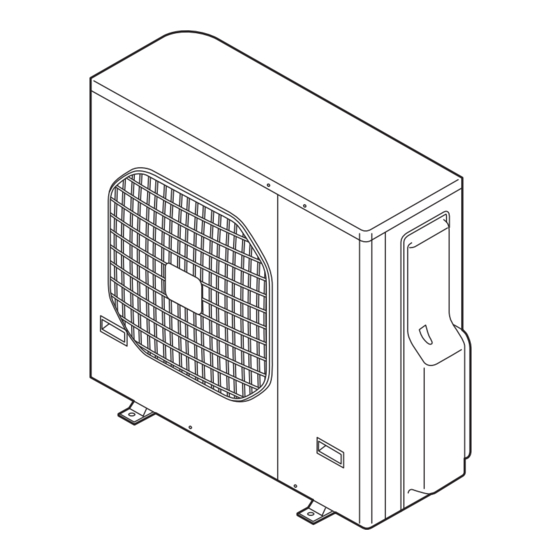
Page 9: Dimensional Data
3. DIMENSIONAL DATA Outdoor Unit CU-5E34NBE AIR INTAKE Wide tube service valve AIR DISCHARGE × dia.9.52 (3/8") Narrow tube service valve × dia.6.35 (1/4") Wide tube service valve × dia.12.70 (1/2") 51 110 Unit: mm (852-0-0010-18600-1) -
Page 10: Refrigerant Flow Diagram
4. REFRIGERANT FLOW DIAGRAM 4-1. Refrigerant Flow Diagram Outdoor Unit CU-5E34NBE Indoor unit Outdoor unit Service valve on wide tube Wide tube Main O.D.12.7mm accumulator accumulator O.D.12.7mm O.D.9.52mm O.D.9.52mm Muffler O.D.9.52mm Header 4-way valve Electric Defrost valve expansion for hot gas bypass valve Service valve on narrow tube... -
Page 11: Performance Data
5. PERFORMANCE DATA 5-1. Temperature Charts × CU-5E34NBE CS-ME7NKE Outdoor Unit Indoor Unit Cooling Characteristics Heating Characteristics (RH : 46%, Indoor fan speed : High fan) (RH : 85%, Indoor fan speed : High fan) (230V, 50Hz) (230V, 50Hz) (1) Low pressure performance chart (1) High pressure performance chart (35.7) Lo fan... - Page 12 × Outdoor Unit CU-5E34NBE Indoor Unit CS-ME9NKE Cooling Characteristics Heating Characteristics (RH : 46%, Indoor fan speed : High fan) (RH : 85%, Indoor fan speed : High fan) (230V, 50Hz) (230V, 50Hz) (1) Low pressure performance chart (1) High pressure performance chart (35.7) Lo fan Mid fan...
- Page 13 × Outdoor Unit CU-5E34NBE Indoor Unit CS-ME12NKE Cooling Characteristics Heating Characteristics (RH : 46%, Indoor fan speed : High fan) (RH : 85%, Indoor fan speed : High fan) (230V, 50Hz) (230V, 50Hz) (1) Low pressure performance chart (1) High pressure performance chart (35.7) Lo fan Mid fan...
- Page 14 × Outdoor Unit CU-5E34NBE Indoor Unit CS-ME18NKE Cooling Characteristics Heating Characteristics (RH : 46%, Indoor fan speed : High fan) (RH : 85%, Indoor fan speed : High fan) (230V, 50Hz) (230V, 50Hz) (1) Low pressure performance chart (1) High pressure performance chart (35.7) Mid fan Hi fan...
- Page 15 × Outdoor Unit CU-5E34NBE Indoor Unit CS-ME24NKE Cooling Characteristics Heating Characteristics (RH : 46%, Indoor fan speed : High fan) (RH : 85%, Indoor fan speed : High fan) (230V, 50Hz) (230V, 50Hz) (1) Low pressure performance chart (1) High pressure performance chart (35.7) Mid fan Hi fan...
-
Page 16: Electrical Data
6. ELECTRICAL DATA 6-1. Electric Wiring Diagrams Outdoor Unit CU-5E34NBE To avoid electrical shock hazard, be sure to WARNING disconnect power before checking, servicing and/or cleaning any electrical parts. 8FA2-5251-19700-2... -
Page 17: Functions
7. FUNCTIONS 7-1. Explanation of Functions Control/conditions Unit operation Explanation INITIAL Breaker is ON. Power is supplied to the indoor and outdoor unit control circuits, however the unit remains stopped. Positioning of the outdoor unit electric expansion valve is performed. The ON/OFF operation If automatic operation mode has been selected This applies in the case of automatic... - Page 18 Control/conditions Unit operation Explanation HEAT Non-stop defrost When defrost operation Defrost operation begins based on outdoor heat begins, frost has formed exchanger temperature and outdoor air on the outdoor unit temperature conditions. Non-stop defrost (Refer to Fig. 1) (when the ambient air Indoor fan : Stopped temperature is low).
- Page 19 Control/conditions Unit operation Explanation COOL The ON/OFF operation The operation lamp illuminates. The outdoor unit does not operate for 5 minutes button on the remote even after the breaker is turned ON. The indoor fan operates at the set fan speed. controller is pressed.
- Page 20 (1/f fluctuation fan) Control/conditions Unit operation Explanation SENSOR The ON/OFF operation The operation lamp illuminates. The outdoor unit does not operate for 5 minutes button on the remote even after the breaker is turned ON. The indoor fan operates at the set fan speed. controller is pressed.
-
Page 21: Protective Functions
7-2. Protective Functions 7-2-1. Defrost Detection and Release (1) Non-stop defrosting Defrosting sequence 4-way valve ON Defrost detection occurs in either of the following cases: • The temperature of the heat exchanger remains at or below the L1 line for 35 minutes after the start of HEAT operation. •... -
Page 22: Current Control
7-2-2. Current Control The operating current may rise as a result of causes including increasing heating or cooling loads or decreases in power voltage. In these cases, the operating frequency is automatically reduced, or operation is stopped, in order to control the operating current so that it is (19.5 A) or less. - Page 23 7-2-3. Low Start Current Operation starts at (8 Hz), and the start current is less than the normal operating current. This prevents the flickering of fluorescent lights or television screens that occurs when ordinary A/C units start. 7-2-4. Compressor Temperature Control To protect the compressor coil from overheating, the operating frequency is controlled based on the compressor discharge temperature.
-
Page 24: Special Functions
7-3. Special Functions 7-3-1. Noise Reducing Control (Outdoor Unit) The noise reducing control is the function used for silent operation of the air conditioner by means of setting the dip switch on the outdoor unit P.C.Board to control the fan and compressor's motor speed. When this function is used, the cooling or heating ability is slightly degraded. - Page 25 7-3-2. Maximum Current Value Change Function The maximum current value is changed to 15.0A or 13.5A to prevent power breaker tripping. (It is set to 20A when the unit is delivered from the factory.) 1. When the high load is given (Outside temperature is high in the cooling operation, or NOTE outdoor temperature is low in the heating operation), the capacity is reduced.
-
Page 26: Troubleshooting (Before Calling For Service)
8. TROUBLESHOOTING (BEFORE CALLING FOR SERVICE) 8-1. Precautions before Performing Inspection or Repair Both the indoor unit and outdoor unit include electronic control circuits. Be sure to pay attention to the following before inspecting or repairing the outdoor- side electronic circuits. High-capacity electrolytic capacitors are used inside the outdoor unit controller (inverter). -
Page 27: Self-Diagnostics
8-2. Self-Diagnostics The self-diagnostics is performed and the results are indicated with the combined patterns of lighting ON, blinking and lighting OFF of the 4 error monitor lamps on the Control P.C.Board. To prevent electric shock, do not inspect or repair until WARNING the Power Lamp on the Control P.C.Board is turned off. - Page 28 8-2-2. Display of the Error Monitor Lamps ..OFF ..Blinking Illuminated ERROR MONITOR LAMP DIAGNOSTICS CONTENTS ERR0 ERR1 ERR2 ERR3 DIAGNOSTICS ITEM SENSOR FOR BRANCH PIPE A FAILURE (NARROW TUBE) SENSOR FOR BRANCH PIPE B FAILURE (NARROW TUBE) SENSOR FOR BRANCH PIPE C FAILURE (NARROW TUBE) SENSOR FOR BRANCH PIPE D...
-
Page 29: Checking The Outdoor System
8-3. Checking the Outdoor System 8-3-1. Checking the outdoor unit Work procedure Check items (unit operation) • • Apply 220 V AC between terminals L and N on the The LED (red) on the control board must illuminate. outdoor unit terminal plate. •... -
Page 30: Trouble Diagnosis Of Each Part
8-4. Trouble Diagnosis of Each Part 8-4-1. Problems of Each Part and Inspection Points For details about the inspection points, refer to the Inspection Points for Each Part. Indoor unit Outdoor unit Others Problems No. of Inspection Points for Each part Inspection points Self-Diagnostics check... - Page 31 8-4-2. Inspection Points for Each Part (1) Outdoor control circuit board Refer to 8-3-1. Checking the outdoor unit. Do not remove or insert the outdoor control circuit board connector when power is being supplied to it. NOTE (The controller will be damaged.) (2) Fuse Check it visually or the continuity with a tester.
- Page 32 (8) Branch tubing temperature sensor Check that the sensor is securely contained in the thermostat holder. (9) Breaker Check whether or not the breaker has been tripped. Check that the breakers and fuses used are of the specified capacity. Check that the breaker and its line are exclusive for A/C use. (10) Refrigerant gas pressure Start a COOL test run, and messure the temperatures of the A/C intake air and discharge air.
-
Page 33: Trouble Diagnosis Of Fan Motor
8-5. Trouble Diagnosis of Fan Motor This outdoor DC fan motor contains an internal control PCB. Therefore, it is not possible to measure the coil resistance, and the following procedure should be used to check the motor. Perform the trouble diagnosis by Test Run mode described on Installation Instructions of indoor unit. Important: (A) Turn OFF the power before connecting or disconnecting the motor connectors. -
Page 34: Refrigerant R410A: Special Precautions When Servicing Unit
9. REFRIGERANT R410A: SPECIAL PRECAUTIONS WHEN SERVICING UNIT 9-1. Characteristics of New Refrigerant R410A 9-1-1. What is New Refrigerant R410A? R410A is a new refrigerant that contains two types of pseudo-non-azeotropic refrigerant mixture. Its refrigeration capacity and energy efficiency are about the same level as the conventional refrigerant, R22. 9-1-2. - Page 35 Tubing precautions Refrigerant R410A is more easily affected by dust or moisture compared with R22, thus be sure to temporarily cover the ends of the tubing with caps or tape prior to installation. Never use 0.7mm-thick copper tubing or tubing which is less than 0.8mm in thickness, since air conditioners with R410A are subject to higher pressure than those using R22 and R407C.
-
Page 36: Tools Specifically For R410A
9-3. Tools Specifically for R410A For servicing, use the following tools for R410A Tool Distinction Tool Name Gauge manifold Charging hose Gas leak detector Refrigerant cylinder Charging cylinder Refrigerant recovery unit Vacuum pump with anti-reverse flow (*1) Tools specifically for R410A (Solenoid valve-installed type, which prevents oil from flowing back into the unit when the power is off, is recommended.) Vacuum pump (*2)...can be used if the following adapter is attached. -
Page 37: In Case Of Compressor Malfunction
9-5. In Case of Compressor Malfunction Should the compressor malfunction, be sure to make the switch to a replacement CAUTION compressor as quickly as possible. Use only the tools indicated exclusively for R410A. See "9-3. Tools Specifically for R410A." 9-5-1. Procedure for Replacing Compressor (1) Recovering refrigerant Any remaining refrigerant inside the unit should not be (1) Recover refrigerant... - Page 38 (5) Recharging Configuration and characteristics of cylinders Be sure to charge the specified amount of Valve refrigerant in liquid state using the service port of the wide tube service valve. The proper amount is listed on the unit's nameplate. When the entire amount cannot be charged all at once, charge gradually while operating the unit in Cooling Operation.
-
Page 39: In Case Refrigerant Is Leaking
9-6. In Case Refrigerant is Leaking Never attempt to charge additional refrigerant when refrigerant has been leaking CAUTION from the unit. Follow the procedure described below to locate points of leaks and carry out repairs, then recharge the refrigerant. (1) Detecting Leaks Use the detector for R410A to locate refrigerant leak points. -
Page 40: Charging Additional Refrigerant
9-7. Charging Additional Refrigerant 9-7-1. When Tubes are Extended Observe the proper amount of refrigerant as stated in this service manual or the installation manual that came with the indoor unit. Charge additional refrigerant in liquid state only. Never charge additional refrigerant if refrigerant is leaking from the unit. Follow CAUTION instructions given in "9-6. -
Page 42: Appendix Ainstallation Instructions
APPENDIX A INSTALLATION INSTRUCTIONS CU-5E34NBE (852-6-4190-578-00-1) - Page 43 For Outdoor Unit INSTALLATION INSTRUCTIONS Split System Air Conditioner Contents This air conditioner uses the refrigerant R410A. Page IMPORTANT! Please Read Before Starting ........2 Model Combinations GENERAL ............4 1-1. Tools Required for Installation (not supplied) Combine indoor and outdoor units only as listed 1-2.
-
Page 44: Please Read Before Starting
IMPORTANT! When Transporting Please Read Before Starting Be careful when picking up and moving the indoor and out- This air conditioner must be installed by the sales dealer or door units. Get a partner to help, and bend your knees when installer. - Page 45 Others • Use the flare method for connecting tubing. • Apply refrigerant lubricant to the matching surfaces of the flare and union tubes before connecting CAUTION them, then tighten the nut with a torque wrench for a leak-free connection. • Ventilate any enclosed areas when installing or •...
-
Page 46: General
1. General This booklet briefly outlines where and how to install 6. Sabre saw or key hole saw the air conditioning system. Please read over the 7. Hacksaw entire set of instructions for the indoor and outdoor 8. Core bits units and make sure all accessory parts listed are with 9. -
Page 47: Additional Materials Required For Installation
1-5. Additional Materials Required for Installation Refrigeration (armored) tape Insulated staples or clamps for connecting wire (See local codes) Putty Refrigeration lubricant Clamps or saddles to secure refrigerant tubing Indoor unit 2. Installation Site Selection 2-1. Indoor Unit To prevent abnormal heat generation WARNING and the possibility of fire, do not place obstacles, enclosures and... -
Page 48: Connecting Indoor Units
install the indoor unit more than 1 meter away from any antenna or power lines or connecting wires used for television, � radio, telephone, security system, or intercom. Electrical noise from any of these sources may affect operation. install in a sturdy manner to avoid increased operating noise. �... - Page 49 Outdoor unit Indoor unit 12.70 (CS-ME18NKE) 12.70 6.35 12.70 (CS-ME18NKE) 12.70 6.35 9.52 (CS-ME7NKE) (CS-ME9NKE) (CS-ME12NKE) 9.52 6.35 9.52 (CS-ME7NKE) (CS-ME9NKE) 9.52 (CS-ME12NKE) 6.35 9.52 (CS-ME7NKE) (CS-ME9NKE) 9.52 (CS-ME12NKE) 6.35 Fig. 4c ( 12.70 15.88) Locally purchased Flare 12.70 Union 15.88 Outdoor unit Indoor unit...
- Page 50 ( 12.70 15.88) Locally purchased Flare 12.70 Union 15.88 Outdoor unit Indoor unit 15.88 (CS-ME24NKE) 12.70 6.35 15.88 (CS-ME24NKE) 12.70 6.35 9.52 (CS-ME7NKE) (CS-ME9NKE) 9.52 (CS-ME12NKE) 6.35 9.52 (CS-ME7NKE) (CS-ME9NKE) 9.52 (CS-ME12NKE) 6.35 9.52 (CS-ME7NKE) (CS-ME9NKE) 9.52 (CS-ME12NKE) 6.35 Fig. 4f Outdoor unit Indoor unit 12.70...
-
Page 51: Outdoor Unit
2-3. Outdoor Unit Exhaust fan AVOID: Hot air heat sources, exhaust fans, etc. (Fig. 5a) � Heat source damp, humid or uneven locations. � Outdoor unit position the outdoor unit in a protected location � where snow will not blow into it. choose a place as cool as possible. -
Page 52: Outer Dimensions Of Outdoor Unit
2-4. Outer Dimensions of Outdoor Unit Service valve on wide tube side (Outer diameter 12.70) Service valve on narrow tube side (Outer diameter 6.35) Service valve on wide tube side (Outer diameter 9.52) Fig. 6a unit: mm Diagram of Outdoor Unit Installation 2-5. -
Page 53: Installation Process
3. Installation Process Embedding the Tubing and Wiring 3-1. Do not connect tubes to locations that are embedded. � Be sure to bind refrigerant tubing and inter-unit cables together with vinyl tape. � The power cable must be obtained on-site. (3.5 mm : Less than 26 m) �... -
Page 54: Caution Before Connecting Tubes Tightly
3-5. Caution Before Connecting Tubes Tightly a) Be sure to apply a sealing cap or water-proof tape to prevent dust or water from getting into the tubes before they are used. b) Be sure to apply refrigerant lubricant to the matching Apply refrigerant surfaces of the flare and union before connecting them together. -
Page 55: Air Purging
4. Air Purging Air and moisture remaining in the refrigerant system have undesirable effects as indicated below. Therefore, they must be purged completely. Service pressure in the system rises valve on � narrow operating current rises Manifold gauge � tube side (special for R410A) cooling efficiency drops Service... - Page 56 (4) With the “Lo” knob of the manifold valve open and high-pressure valve (“Hi”) closed completely, run the vacuum pump. Run the pump until the pressure is –101 kPa (–76 cmHg). The operation time for the vacuum pump varies with tubing length and the capacity of the pump. The following table shows the amount of time required for evacuation: Table 5 Required time for evacuation when capacity...
-
Page 57: Pump Down
Pump Down � In order to protect the earth’s environment, be sure to perform pump-down to recover refrigerant gas without releasing it into the atmosphere. Close When relocating or disposing of the air conditioner, � request this service from the dealer where the unit was purchased, or from an appropriate agent. -
Page 58: Wiring Instructions
5. Wiring Instructions 5-1. General Precautions on Wiring (1) Before wiring, confirm the rated voltage of the unit as shown on its nameplate, then carry out the wiring closely following the wiring diagram. (2) Provide a power outlet to be used exclusively for each unit, with a power supply disconnect and leakage breaker/fuse link for overcurrent protection provided in the exclusive line. -
Page 59: Wiring System Diagram
5-3. Wiring System Diagram (Fig. 25) OUTDOOR UNIT 5-4. How to Connect Wiring to the Terminal Grounding line Loose wiring may cause the terminal to WARNING overheat or result in unit malfunction. A fire hazard may also exist. Therefore, be sure all wiring is tightly connected. -
Page 60: Wiring Instructions For The Outdoor Unit
5-5. Wiring Instructions for the Outdoor Unit CAUTION Be sure to correctly align inter-unit cables A, B, C, D and E. � Outdoor unit Terminal board Power: Single-phase, 220 - 230 - 240 VAC 50Hz Leakage breaker/fuse link Indoor unit E (not provided) E is the indoor unit with Ground... -
Page 61: Test Run
Regulations on wire size differ from locality to locality. For field wiring requirements, please refer to your local electrical codes. Cabinet Make sure that the installation fully complies with all local and national regulations. (1) Remove access panel “C” and the terminal cover. (Fig. 32) (2) Connect the inter-unit wiring and power line according to the drawing on the panel side. -
Page 62: Installation Check Sheet
8. Installation Check Sheet The strength of the installation location is sufficient to support the air conditioner weight. The indoor and outdoor units are installed level and vertically. The power and voltage are as specified. Inter-unit cables are securely fastened to the terminal board. Inter-unit cables are securely fixed. - Page 65 Para unidad exterior INSTRUCCIONES DE INSTALACIÓN Acondicionado de Aire de Sistema Separado Índice Este acondicionador de aire emplea el refrigerante R410A. Página ¡IMPORTANTE! Por favor, lea antes de comenzar......2 Combinaciones de modelos GENERAL ............4 1-1. Herramientas necesarias para la instalación Combine las unidades interna y externa sólo de (no suministradas) 1-2.
- Page 66 ¡IMPORTANTE! Durante el transporte Por favor, lea antes de comenzar Sea cuidadoso cuando levante y transporte las unidades interna y externa. Consiga un ayudante, y doble sus rodillas cuando levante El instalador o el distribuidor de ventas deben ser los encargados de para reducir el esfuerzo de su espalda.
- Page 67 Otros de la bocina y los tubos de unión antes de conectarlos, luego PRECAUCIÓN apriete la tuerca con una llave de torsión para lograr una conexión libre de filtraciones. arrancar la operación de prueba. prueba del sistema de refrigeración. El gas refrigerante que escapa, en contacto con el fuego o el calor, puede producir gases tóxicos peligrosos.
- Page 68 1. GENERAL 5. Nivel de carpintero Este manual describe brevemente dónde y cómo 6. Sierra de arco o sierra de orificio muescada instalar el sistema acondicionador de aire. Por favor 7. Sierra cortametales lea el conjunto completo de instrucciones para las 8.
- Page 69 1-5. Materiales adicionales requeridos para la instalación Cinta de refrigeración (blindada) Grampas o abrazaderas aisladas para el cable de conexión (véanse los códigos locales) Masilla Lubricante de refrigeración Abrazaderas o monturas para asegurar la tubería refrigerante Unidad interna 2. SELECCIÓN DEL SITIO DE INSTALACIÓN 2-1.
- Page 70 Instale la unidad interior separada en más de 1 metro de cualquier antena o línea de poder, o cables de conexión � usados para la televisión, radio, teléfono, sistema de seguridad o intercomunicador. El ruido electrico proveniente de cualquiera de estas fuentes puede afectar la operación. Efectúe la instalación con una fijación fuerte para evitar que aumente el ruido de funcionamiento.
- Page 71 Unidad exterior Unidad interior 12,70 (CS-ME18NKE) 12,70 6,35 12,70 (CS-ME18NKE) 12,70 6,35 9,52 (CS-ME7NKE) (CS-ME9NKE) 9,52 (CS-ME12NKE) 6,35 9,52 (CS-ME7NKE) (CS-ME9NKE) 9,52 (CS-ME12NKE) 6,35 9,52 (CS-ME7NKE) (CS-ME9NKE) 9,52 (CS-ME12NKE) 6,35 Fig. 4c ( 12,70 15,88) Comprada localmente Abocinamiento 12,70 Unión 15,88 Unidad exterior Unidad interior...
- Page 72 ( 12,70 15,88) Comprada localmente Abocinamiento 12,70 Unión 15,88 Unidad exterior Unidad interior 15,88 (CS-ME24NKE) 12,70 6,35 15,88 (CS-ME24NKE) 12,70 6,35 9,52 (CS-ME7NKE) (CS-ME9NKE) 9,52 (CS-ME12NKE) 6,35 9,52 (CS-ME7NKE) (CS-ME9NKE) 9,52 (CS-ME12NKE) 6,35 9,52 (CS-ME7NKE) (CS-ME9NKE) 9,52 (CS-ME12NKE) 6,35 Fig. 4f Unidad exterior Unidad interior 12,70...
- Page 73 2-3. Unidad exterior Ventilador de escape EVITE: Aire caliente Fuente de calor Fuentes de calor, ventiladores de escape, etc. � (Fig. 5a) Unidad exterior Lugares mojados, húmedos o irregulares. � EFECTÚE: Instale la unidad exterior en un lugar protegido en el �...
- Page 74 2-4. Dimensiones exteriores de la unidad exterior Válvula de servicio en el lado del tubo ancho (Diámetro exterior ø 12,70 ) Válvula de servicio en el lado del tubo estrecho (Diámetro exterior ø 6,35 ) Válvula de servicio en el lado del tubo ancho (Diámetro exterior ø...
- Page 75 3. INSTALACIÓN DE LA UNIDAD INTERIOR Unidad exterior 3-1. Empotramiento de tuberías y cables � No conecte tubos a lugares que estén empotrados. � Cerciórese de unir las tuberías de refrigerante y los cables entre unidades juntos con cinta de vinilo. �...
- Page 76 3-5. Precaución antes de la conexión firme de los tubos Asegúrese de aplicar una tapa de sellado o cinta a prueba de agua para evitar que el polvo o el agua entren en los tubos antes de que sean usados. Asegúrese de aplicar lubricante de refrigerante en las superficies en contacto de las bocinas y Aplique lubricante de uniones antes de conectarlas.
-
Page 77: Purga De Aire
4. PURGA DE AIRE El aire y la humedad que permanecen en el sistema refrigerante tienen efectos indeseables como se indica abajo. Por lo tanto, éstos deben Válvula de ser purgados totalmente. servicio en el lado del La presión en el sistema aumenta �... - Page 78 (4) Con la perilla “Lo” de la válvula distribuidora abierta y la válvula de alta presión (“Hi”) completamente cerrada, ponga en funcionamiento la bomba de vacío. Deje en funcionamiento la bomba de vacío hasta que la presión sea de –101 kPa (–76 cmHg). El tiempo de operación de la bomba de vacío variará de acuerdo con la longitud de la tubería y la capacidad de la bomba.
- Page 79 � Bomba abajo Para proteger el medio ambiente, cerciórese de realizar el vaciado con bomba para recuperar el gas refrigerante sin soltarlo a la atmósfera. Cerrar Cuando desee cambie de lugar o tirar el acondicionador de � aire, solicite este servicio al proveedor donde haya adquirido la unidad, o a un agente apropiado.
- Page 80 5. INSTRUCCIONES DE CABLEADO 5-1. Precauciones generales sobre el cableado (1) Antes de efectuar el cableado, confirme el voltaje nominal de la unidad como se indica en la placa de identifica- ción, luego efectúe el cableado siguiendo meticulosamente el diagrama de cableado. (2) Disponga una toma de alimentación a ser usada exclusivamente para cada unidad, con la alimentación desconectada y un disyuntor de fugas/elemento fusible para protección contra sobrecorriente de la línea exclusiva.
- Page 81 5-3. Diagrama de cableado del sistema (Fig. 25) UNIDAD EXTERNA 5-4. Conexión del cableado al terminal El cableado suelto puede causar que el ter- Línea de toma de tierra (B) minal se sobrecaliente o puede causar ADVERTENCIA mala operación en la unidad. También se produce el peligro de fuego.
- Page 82 5-5. Instrucciones de cableado para la unidad exterior PRECAUCIÓN Cerciórese de alinear correctamente los cables entre las unidades A, B, C, D y E. � Unidad exterior Tablero de terminales Alimentación: 50Hz, monofásica 220 - 230 - 240 V CA Disyuntor de fugas/ elemento fusible Unidad interior E...
- Page 83 Los reglamentos sobre el tamaño de cable difieren de localidad a Gabinete localidad. Para los requerimientos de cableado en terreno, por favor, refiérase a sus códigos eléctricos locales. Asegúrese que la instalación cumpla completa- mente con todos los reglamentos locales y nacionales. (1) Remueva el panel de acceso “C”...
- Page 85 Pour unité extérieure INSTRUCTIONS D’INSTALLATION Climatiseur système divisé Sommaire Ce climatiseur utilise le réfrigérant R410A. Page IMPORTANT! Veuillez lire ce qui suit avant de commencer ..2 Combinaison de modèles INFORMATION GÉNÉRALE ......4 1-1. Les outils nécessaires à l’installation N’associez les appareils intérieurs et extérieurs (non fournis) 1-2.
-
Page 86: Veuillez Lire Ce Qui Suit Avant De Commencer
IMPORTANT! Lors du transport Veuillez lire ce qui suit avant de commencer Soyez prudent lorsque vous soulevez et déplacez les appareils intérieur et extérieur. Demandez à un collègue de vous aider, et Ce climatiseur doit être installé par le revendeur ou l’installateur. pliez les genoux lors du levage afin de réduire les efforts sur Ces informations sont fournies au seul usage des personnes votre dos. - Page 87 Divers tuyaux. regard des tuyaux d’évasement et d’union avant de les PRUDENCE connecter, puis serrez l’écrou avec une clé dynamométrique pour effectuer une connexion sans fuite. d’effectuer l’essai de fonctionnement. système de réfrigération. Du gaz réfrigérant qui a fui peut, au contact de feu ou de chaleur, produire un gaz du travail de tuyauterie en cas de montage ou remontage et dangereusement toxique.
-
Page 88: Information Générale
1. Information générale 4. Un ruban à mesurer 5. Un niveau de charpentier comment installer le système de conditionnement de 6. Une scie sauteuse ou une scie à guichet l’air. Veuillez lire l’intégralité des instructions des 7. Une scie à métaux appareils intérieur et extérieur, et vous assurer que 8. -
Page 89: Matériaux Supplémentaires Nécessaires À L'installation
1-5. Matériaux supplémentaires nécessaires à l’installation 1. Bande de réfrigération (armée) 2. Des agrafes ou des attaches isolées pour les fils de connexion (se reporter aux réglementations locales) 3. Du mastic 4. Du lubrifiant de réfrigération 5. Des attaches ou des cavaliers pour fixer les tuyaux de réfrigérant Appareil intérieur 2. -
Page 90: Connexion D'unités Intérieures
Installez l’appareil intérieur à plus d’1 mètre d’une antenne, de lignes de transport d’énergie ou de câbles de raccordement � utilisés pour un téléviseur, une radio, un téléphone, un système de sécurité ou un interphone. Des parasites électriques provenant de l’une de ces sources pourraient affecter le fonctionnement. installer solidement de sorte à... - Page 91 Appareils extérieurs Appareils intérieurs 12,70 (CS-ME18NKE) 12,70 6,35 12,70 (CS-ME18NKE) 12,70 6,35 9,52 (CS-ME7NKE) (CS-ME9NKE) 9,52 (CS-ME12NKE) 6,35 9,52 (CS-ME7NKE) (CS-ME9NKE) 9,52 (CS-ME12NKE) 6,35 9,52 (CS-ME7NKE) (CS-ME9NKE) 9,52 (CS-ME12NKE) 6,35 Fig. 4c ( 12,70 15,88) Achetée localement Conique 12,70 Raccord 15,88 Appareils extérieurs Appareils intérieurs...
- Page 92 ( 12,70 15,88) Achetée localement Conique 12,70 Raccord 15,88 Appareils extérieurs Appareils intérieurs 15,88 (CS-ME24NKE) 12,70 6,35 15,88 (CS-ME24NKE) 12,70 6,35 9,52 (CS-ME7NKE) (CS-ME9NKE) (CS-ME12NKE) 9,52 6,35 9,52 (CS-ME7NKE) (CS-ME9NKE) 9,52 (CS-ME12NKE) 6,35 9,52 (CS-ME7NKE) (CS-ME9NKE) 9,52 (CS-ME12NKE) 6,35 Fig. 4f Appareils extérieurs Appareils intérieurs 12,70...
-
Page 93: L'appareil Extérieur
2-3. L’appareil extérieur Ventilateur ÉVITEZ: d’évacuation Air chaud Les sources de chaleur, les ventilateurs � d’évacuation, etc. (Fig. 5a) Source de chaleur Les endroits mouillés, humides ou de surface Appareil � extérieur irrégulière. RECHERCHEZ: Installez l’appareil extérieur dans un endroit �... -
Page 94: Dimensions Extérieures D'unité Extérieure
2-4. Dimensions extérieures d’unité extérieure Robinet de service sur côté tube large (Diamètre extérieur ø 12,70 ) Robinet de service sur côté tube étroit (Diamètre extérieur ø 6,35 ) Robinet de service sur côté tube large (Diamètre extérieur ø 9,52 ) Fig. -
Page 95: Procede D'installation
3. Procede d’installation 3-1. Encastrage du tubage et du câblage � Ne pas connecter de tubes aux endroits qui sont encastrés. � � Le câble d’alimentation doit être obtenu sur place. (3,5 mm : Inférieur à 26 m) � � Bien obturer l’extrémité de tube encastré avec un ruban de vinyle pour éviter la pénétration de saleté ou d’humidité. �... -
Page 96: Les Précautions À Prendre Avant De Serrer Les Raccords Des Tuyaux
3-5. Les précautions à prendre avant de serrer les raccords des tuyaux a) Veillez à appliquer un couvercle de bouchage ou une bande étanche pour éviter la pénétration de poussière ou d’eau dans les tuyaux avant leur utilisation. b) Veillez à appliquer du lubrifiant de réfrigération aux surfaces en contact de l’évasement et de Appliquez du lubrifiant pour l’union avant de les raccorder ensemble. -
Page 97: La Purge De L'air
4. La purge de l’air L’air et l’humidité subsistant dans le système du réfrigérant ont des effets indésirables qui sont Robinet de Soupape basse énumérés ci-dessous. Par conséquent, ils doivent service pression être complètement purgés. sur côté Collecteur tube étroit (spécial pour R410A) La pression du système augmente �... - Page 98 (4) Le bouton “Lo” de la soupape collectrice étant ouvert et la soupape haute pression (“Hi”) étant complètement d’opération de la pompe à vide varie avec la longueur du tube et la capacité de la pompe. Le tableau suivant montre la durée nécessaire à...
-
Page 99: L'évacuation Par Pompage
� L’évacuation par pompage Pour protéger l’environnement de la terre, toujours effectuer l’évacuation pour récupérer le gaz réfrigérant sans le relâcher dans l’atmosphère. En cas relocalisation ou de mise au rebut du climatiseur, � Fermer ou chez un agent agréé. Effectuer l’évacuation de la manière décrite ci-dessous. -
Page 100: Les Instructions De Câblage
5. Les instructions de câblage 5-1. Les précautions générales à prendre lors du câblage (1) Avant de procéder au câblage, vérifiez le voltage pour lequel est prévu l’appareil, tel qu’il est indiqué sur la plaque du constructeur, puis effectuez le câblage en suivant soigneusement le schéma de câblage. (2) Affectez à... -
Page 101: Diagramme De Système De Câblage
Appareil extérieur 5-3. Diagramme de système de câblage (Fig. 25) 5-4. Comment connecter le câble à la borne Un câble mal serré peut avoir pour résultat Ligne de mise à la terre une surchauffe du bornier ou un mauvais DANGER fonctionnement de l’appareil. -
Page 102: Instructions De Câblage Pour L'unité Extérieure
5-5. Instructions de câblage pour l’unité extérieure PRUDENCE Toujours aligner correctement les câbles entre unités A, B, C, D et E. � Unité extérieure Plaquette de bornes Source d’alimentation: 50 Hz, Monophasé, 220 - 230 - 240 V Disjoncteur/raccord fusible Unité... -
Page 103: Marche D'essai
Les réglementations concernant le dimensionnement des câbles Boîtier varient selon les localités. Pour les exigences du câblage sur le site, veuillez consulter les réglementations électriques locales. Assurez- vous que l’installation respecte intégralement toutes les réglementa- tions locales et nationales. (1) Retirez le panneau d’accès “C” et le cache-borne. (Fig. 32) (2) Connectez le câble et la ligne d’alimentation entre les appareils selon le schéma se trouvant sur le panneau latéral. - Page 105 Für Außengeräte INSTALLATIONSANLEITUNGEN Klimaanlage mit Split-System Inhalt Diese Klimaanlage verwendet das Kühlmittel R410A. Seite WICHTIG! Bitte vor Arbeitsbeginn lesen......... 2 Modellkombinationen ALLGEMEINES..........4 1-1. Für die Installation erforderliche Werkzeuge Innenraum- und Außengeräte sollen nur wie (nicht mitgeliefert) in der folgenden Liste miteinander verbunden 1-2.
-
Page 106: Bitte Vor Arbeitsbeginn Lesen
WICHTIG! Transport Bitte vor Arbeitsbeginn lesen Heben und bewegen Sie die Innenraum- und Außengeräte mit Die Installation der Klimaanlage muss von dem Vertrieb oder einem großer Vorsicht. Lassen Sie sich helfen und beugen Sie die Knie, Installateur durchgeführt werden. um die Belastung auf den Rücken zu verringern. Scharfe Kanten Diese Informationen richten sich ausschließlich an autorisiertes oder die dünnen Aluminiumrippen des Klimatisierungsgerätes Fachpersonal. - Page 107 Sonstige Hinweise Rohrenden und Verbindungsrohre, ziehen Sie dann die Mutter VORSICHT mit einem Drehmomentschlüssel zu, um eine dichte Verbindung zu erhalten. Vor dem Einbau des Gerätes sicherstellen, daß die Räumlichkeiten vor dem Einbau gründlich gelüftet worden sind. Wenn Rückstände von Kühlmittelgasen mit offenem Feuer, oder oder erneuten Installation sowie während der Instandsetzung von starken Hitzequellen in Berührung kommen, so kann dies zu der Teilen des Kühlmittelkreislaufs darauf achten, dass kein...
-
Page 108: Allgemeines
1. Allgemeines 4. Meßband 5. Wasserwaage Diese Broschüre beschreibt in groben Zügen, wo und 6. Stichsäge wie die Klimaanlage installiert werden soll. Bitte lesen 7. Bügelsäge Sie alle Anleitungen für die Innenraum- und 8. Bohrspitzen Außengeräte durch und stellen Sie sicher, daß sich alle 9. -
Page 109: Zusätzliche Materialien, Die Für Die Installation Notwendig Sind
1-5. Zusätzliche Materialien, die für die Installation notwendig sind Kühlband (bewehrt) 2. Isolierte Klammern, um die Kabel zu verbinden (siehe örtliche Vorschriften). Dichtungsmasse Kühlschmierfett 5. Klammern oder Rohrschellen, um die Kühlrohre zu befestigen. Innengerät 2. Wahl des Installationsortes 2-1. Innenraumgerät Um anormale Hitzeerzeugung und WARNUNG Brandgefahr zu vermeiden, stellen Sie... -
Page 110: Anschließen Der Inneneinheiten
� Installieren Sie das Innenraumgerät in einem Abstand von mindestens 1 Meter zu Antennen, Strom- oder Anschlußkabeln von Fernsehgeräten, Radios und Telefonen, Sicherheitsanlagen oder Gegensprechanlagen. Elektrische Störgeräusche könnten sonst den Betrieb der Klimaanlage beeinflussen. � Beim Einbau sicher befestigen und erhöhtes Betriebsgeräusch vermeiden. Tabelle 3 Max. - Page 111 Außengeräte Innenraumgeräte 12,70 (CS-ME18NKE) 12,70 6,35 12,70 (CS-ME18NKE) 12,70 6,35 9,52 (CS-ME7NKE) (CS-ME9NKE) 9,52 (CS-ME12NKE) 6,35 9,52 (CS-ME7NKE) (CS-ME9NKE) 9,52 (CS-ME12NKE) 6,35 9,52 (CS-ME7NKE) (CS-ME9NKE) (CS-ME12NKE) 9,52 6,35 Abb. 4c ( 12,70 15,88) Vor Ort gekauft Aufweitung 12,70 Verbindungsrohr 15,88 Außengeräte Innenraumgeräte 15,88...
- Page 112 ( 12,70 15,88) Vor Ort gekauft Aufweitung 12,70 Verbindungsrohr 15,88 Außengeräte Innenraumgeräte 15,88 (CS-ME24NKE) 12,70 6,35 15,88 (CS-ME24NKE) 12,70 6,35 9,52 (CS-ME7NKE) (CS-ME9NKE) 9,52 (CS-ME12NKE) 6,35 9,52 (CS-ME7NKE) (CS-ME9NKE) 9,52 (CS-ME12NKE) 6,35 9,52 (CS-ME7NKE) (CS-ME9NKE) 9,52 (CS-ME12NKE) 6,35 Abb. 4f Außengeräte Innenraumgeräte 12,70...
-
Page 113: Außengerät
2-3. Außengerät Nein VERMEIDEN SIE: Sauggebläse Heiße Luft Wärmequellen, Sauggebläse, etc. (Abb. 5a) � Wärmequelle nasse, luftfeuchte oder unebene Stellen. � WAS SIE TUN SOLLTEN: Außengerät Stellen Sie das Außengerät an einer geschützten � Stelle auf, wo es nicht mit Schnee in Kontakt kommt. -
Page 114: Außenmaße Der Außeneinheit
2-4. Außenmaße der Außeneinheit Wartungsventil auf der Seite der größeren Leitung (Außendurchmesser ø12,70) Wartungsventil auf der Seite der kleineren Leitung (Außendurchmesser ø6,35) Wartungsventil auf der Seite der größeren Leitung (Außendurchmesser ø9,52) Abb. 6a Einheit: mm 2-5. Schaubild der Außeneinheit-Installation Niemals nur eine einzelne Inneneinheit installieren. Unbedingt darauf achten, dass die Innen- und Außeneinheiten nur in den Kombinationen verbunden werden, die im Katalog oder der Konfigurationstabelle... -
Page 115: Vorgehensweise Bei Der Installation
3. Vorgehensweise bei der Installation 3-1. Einbetten der Leitungen und Kabel � Die Leitungen dürfen nicht mit eingebetteten Anschlüssen verbunden werden. � Die Kühlmittelleitungen und die Geräteverbindungskabel müssen unbedingt mit Klebeband zusammengebunden werden. : Weniger als 26 m) � � Unbedingt die mitgelieferten Aufkleber an beiden Enden der Geräteverbindungskabel anbringen, um einen inkorrekten Anschluss zu vermeiden. -
Page 116: Bevor Sie Die Rohre Fest Miteinander Verbinden
3-5. Bevor Sie die Rohre fest miteinander verbinden Benutzen Sie einen dichten Verschluß oder wasserfestes Klebeband, um zu verhindern, daß Staub oder Wasser vor der Benutzung in die Rohre gelangen. Streichen Sie Kühlmittel- werden, vor ihrer Verbindung mit Kühlmittel-Schmierfett. Dies wird zu einer Reduzierung von Schmierfett auf diese Stellen Gaslecks beitragen. -
Page 117: Entfernen Der Luft
4. Entfernen der Luft Im Kühlmittelsystem verbleibende Luft und Feuchtigkeit haben die unten aufgezählten Niederdruckventil unerwünschten Auswirkungen. Deshalb muß die Luft vollständig entfernt werden. Wartungsventil auf der Seite Der Druck im System steigt. � der kleineren Der Betriebsstrom steigt. Leitung �... - Page 118 (4) Die Unterdruckpumpe einschalten, wobei der “Lo”-Knopf des Mehrwegeventils geöffnet, aber das Hochdruckventil (“Hi”) ganz geschlossen sein muss. Die Pumpe laufenlassen, bis ein Unterdruckwert von –101 kPa (–76 cmHg) angezeigt wird. Die Betriebszeit der Unterdruckpumpe ist je nach Leitungslänge und Kapazität der Pumpe verschieden.
-
Page 119: Auspumpen
� Auspumpen Aus Umweltschutzgründen ist das Auspumpen ist wie nachstehend beschrieben auszuführen, damit das Kühlmittelgas aufgefangen wird und nicht in die Umgebungsluft entweichen kann. � oder das Kühlmittel entsorgt werden soll, ist hierzu entweder Schließen der Händler zu Rate zu ziehen, bei dem die Anlage gekauft wurde, oder es muss ein mit diesen Arbeiten vertrautes Schließen Unternehmen beauftragt werden. -
Page 120: Verdrahtungsanleitungen
5. Verdrahtungsanleitungen 5-1. Allgemeine Vorsichtsmaßnahmen bei der Verdrahtung (1) Sehen Sie vor der Verdrahtung auf das Typenschild des Gerätes, um sich über seine nominelle Spannung zu infor- mieren. Folgen Sie dann bei der Verdrahtung dem Schaltbild. (2) Sorgen Sie für eine Kraftstromsteckdose pro Gerät, mit einem Stromversorgungsunterbrecher und Erdschluss- Stromunterbrecher/Schmelzeinsatz, um die jeweilige Leitung mit einem Schutz vor Überlastung zu versehen. -
Page 121: Stromlaufplan
Außengerät 5-3. Stromlaufplan (Abb. 25) 5-4. Anschließen der Kabel an der Klemme Erdungsleitung Lose Kabel können zur Überhitzung des WARNUNG Anschlusses oder Fehlfunktion des Gerätes führen. Feuergefahr mag ebenfalls bestehen. Stellen Sie daher sicher, daß alle Kabelverbin- dungen fest sind. Erdungsleitung Folgen Sie der Anleitung “Wie man Kabel mit dem Anschluß... -
Page 122: Hinweise Zum Verkabeln Der Außeneinheit
5-5. Hinweise zum Verkabeln der Außeneinheit VORSICHT Unbedingt die Geräteverbindungskabel A, B, C, D und E korrekt ausrichten. � Außengerät Klemmenbrett Netzanschluß 50 Hz Einphasen 220 - 230 - 240 V Erdschluss-Stromunterbrecher Inneneinheit E /Schmelzeinsatz (nicht mitgeliefert) Mit “E” wird die Inneneinheit bezeichnet, Masse deren Kühlmittelleitung mit Klemmenbrett... -
Page 123: Probelauf
schieden. Bitte beachten Sie die auf Sie zutreffenden Vorschriften, um Gehäuse die Erfordernisse für Verdrahtungsarbeiten außerhalb des Hauses zu erfahren. Stellen Sie sicher, daß sich die Installation vollständig im Einklang mit regionalen und nationalen Gesetzen befindet. (1) Entfernen Sie die Abdeckplatte “C” und die Klemmenabdeckung. (Abb. - Page 125 Per unità esterna ISTRUZIONI DI INSTALLAZIONE Condizionatore d’aria a sistema split Contenuto Questo condizionatore d’aria usa il refrigerante R410A. Pagina IMPORTANTE! Leggere prima di iniziare l’installazione....2 Combinazione Modelli AVVERTENZE GENERALI ........ 4 1-1. Attrezzi necessari per l’installazione (non forniti) Combinare Unità...
-
Page 126: Leggere Prima Di Iniziare L'installazione
IMPORTANTE! Durante il trasporto Leggere prima di iniziare l’installazione Fare attenzione nel sollevare e nello spostare le unità interna ed esterna. E’ consigliabile farsi aiutare da Questo condizionatore deve essere installato dal proprio qualcuno e piegare i ginocchi quando si solleva per evitare rivenditore o da un installatore qualificato. - Page 127 Altre norme cartellatura e avvitare con le mani, quindi stringere le con- PRECAUZIONE nessioni utilizzando una chiave dinamometrica in modo da ottenere un collegamento a buona tenuta. prima della prova di funzionamento (test run). bene il luogo di lavoro. Il gas refrigerante, a contatto con dell’installazione o della re-installazione, e così...
-
Page 128: Avvertenze Generali
1. Avvertenze generali 5. Livella Questo manuale spiega brevemente come installare il 6. Punta fresa a tazza condizionatore. Si prega di leggere attentamente tutte 7. Seghetto le istruzioni, Unità Interna ed Esterna, ed assicurarsi di 8. Punta da trapano avere tutti gli accessori qui elencati prima di iniziare. 9. -
Page 129: Materiale Addizionale Per L'installazione
1-5. Materiale addizionale per l’installazione Nastro isolante per circuito frigorifero Forcelle o morsetti isolanti per il collegamento dei cavi (vedere norme locali) Stucco Fascette o staffe per fissare la tubazione 2. Scelta del luogo di installazione Unità Interna 2-1. Unità interna AVVERTIMENTO Per prevenire produzione di calore e conseguente incendio, non apporre ostacoli,... -
Page 130: Collegamento Di Unità Interne
Installare l’unità esterna a più di un metro da antenne, linee elettriche o cavi di collegamento per televisori, radio, � funzionamento dell’apparecchio. installare in modo sicuro per evitare rumori durante il lavoro. � Tabella 3 Lunghezza Lunghezza massima Limite della Massimo dislivello Qtà... - Page 131 Unità esterne Unità interne 12,70 (CS-ME18NKE) 12,70 6,35 12,70 (CS-ME18NKE) 12,70 6,35 9,52 (CS-ME7NKE) (CS-ME9NKE) 9,52 (CS-ME12NKE) 6,35 9,52 (CS-ME7NKE) (CS-ME9NKE) 9,52 (CS-ME12NKE) 6,35 9,52 (CS-ME7NKE) (CS-ME9NKE) (CS-ME12NKE) 9,52 6,35 Fig. 4c ( 12,70 15,88) Da acquistare in loco Svasatura 12,70 Raccordo 15,88...
- Page 132 ( 12,70 15,88) Da acquistare in loco Svasatura 12,70 Raccordo 15,88 Unità esterne Unità interne 15,88 (CS-ME24NKE) 12,70 6,35 15,88 (CS-ME24NKE) 12,70 6,35 9,52 (CS-ME7NKE) (CS-ME9NKE) (CS-ME12NKE) 9,52 6,35 9,52 (CS-ME7NKE) (CS-ME9NKE) 9,52 (CS-ME12NKE) 6,35 9,52 (CS-ME7NKE) (CS-ME9NKE) 9,52 (CS-ME12NKE) 6,35 Fig.
-
Page 133: Unità Esterna
2-3. Unità esterna Aspiratore EVITARE: Aria calda La vicinanza a fonti di calore od aree interessate da � Fonte di espulsioni di aria calda. (Fig. 5a) calore Zone con rischio di allagamenti e piano di appoggio � Unità Esterna non livellato. E’PREFERIBILE: Mettere l’Unità... -
Page 134: Dimensioni Sterne Dell'unità Esterna
2-4. Dimensioni sterne dell’unità esterna Valvola di servizio sul lato del tubo di lume superiore (Diametro esterno ø12,70) Valvola di servizio sul lato del tubo di lume inferiore (Diametro esterno ø6,35) Valvola di servizio sul lato del tubo di lume superiore (Diametro esterno ø9,52) Fig. -
Page 135: Processo Di Installazione
3. Processo di installazione 3-1. Incassamento dei tubi e cavi � Non collegare tubi a locazioni incassate nel muro. � Fissare insieme tubazioni del gas refrigerante e cavi fra unità con nastro isolante. � Il cavo di alimentazione deve venire procurato in loco. (3,5 mm : meno di 26 m) �... -
Page 136: Alcuni Accorgimenti Prima Di Collegare E Stringere I Tubi
3-5. Alcuni accorgimenti prima di collegare e stringere i tubi a) Applicare un tappo a tenuta o nastro impermeabile per evitare l’introduzione di polvere o acqua all’interno del tubo prima dell’uso. Applicare olio b) Applicare olio anticongelante sulle superfici di contatto, quindi avvitare con le mani. anticongelante Questa operazione è... -
Page 137: Spurgo Aria
4. Spurgo aria Aria ed umidità nel circuito frigorifero provocano Valvola di bassa pressione Valvola di eseguire uno spurgo completo. Misuratore a collettore servizio sul (speciale per R410A) lato del tubo aumento della pressione nel circuito � di lume Valvola ad alta aumento della corrente inferiore pressione... - Page 138 (4) Con la manopola “Lo” della valvola a collettore aperta e la valvola della alta pressione “Hi” del tutto chiusa, fare andare la pompa a vuoto. Farla girare fino a che la pressione è di –101 kPa (–76 cmHg). Il tempo richiesto varia a seconda della lunghezza delle tubazioni e della capacità...
-
Page 139: Pompa Giù
� Pompa giù Per proteggere l’ambiente, eseguire sempre il procedimento di recupero del gas refrigerante per poter recuperare il gas refrigerante senza disperderlo nell’atmosfera. Prima di spostare o gettare il condizionatore d’aria, chiedere � Chiudere al negozio di acquisto del condizionatore d’aria o a personale specializzato di fare quest’operazione. -
Page 140: Istruzioni Collegamento Elettrico
5. Istruzioni collegamento elettrico 5-1. Precauzioni generali sul collegamento elettrico (1) Prima di eseguire il colegamento elettrico, verifi-care la tensione nominale dell’unità, poi seguire dettaglitamente lo schema elettrico. come indicato nello schema di collegamento. L’interruttore di circuito deve venire incorporato nei cablaggi fissi in accordo con le regolamentazioni in materia. L’interruttore di circuiti deve avere i 25 A approvati e tutte le polarità... -
Page 141: Diagramma Dell'impianto Elettrico
UNITÀ ESTERNA 5-3. Diagramma dell’impianto elettrico (Fig. 25) 5-4. Collegamento dei fili al loro terminale Linea di messa a terra Accertarsi che i terminali dei cavi AVVERTIMENTO elettrici siano ben stretti sulla morsettiera. Terminali non stretti causano surriscaldamento alla morsettiera, problemi al funzionamento Linea di messa a terra del condizionatore d’aria con pericolo di inizio di incendio. -
Page 142: Messa In Posa Dei Fili Dell'unità Esterna
5-5. Messa in posa dei fili dell’unità esterna PRECAUZIONE Non mancare di allineare correttamente i cavi fra unità A, B, C, D e E. � Unità Esterna Scheda dei terminali Energia elettrica 50 Hz Monofase 220 - 230 - 240 V Interruttore di dispersione/ filo fusibile Unità... -
Page 143: Prova Di Funzionamento
Le regole sulla sezione dei cavi si differenzia da luogo a luogo; fare quindi Armadietto regole durante l’installazione. (1) Rimuovere il pannello di accesso “C” ed il coperchio dei terminali. (Fig. 32) (2) Collegare i fili elettrici di potenza e di collega-mento tra le unità secondo il disegno applicato sul pannello laterale. - Page 145 Para unidade exterior INSTRUÇÕES DE INSTALAÇÃO Aparelho de Ar Condicionado Bipartido Índice Página Este aparelho de ar condicionado utiliza o IMPORTANTE! Queira ler antes de colocar a unidade em refrigerante R410A. funcionamento............2 GENERALIDADES..........4 1-1. Ferramentas necessárias para a instalação Combinações de Modelos (não fornecidas) 1-2.
- Page 146 IMPORTANTE! Durante o Transporte Queira ler antes de colocar a unidade em Tome cuidado quando levantar e deslocar as unidades para uso funcionamento no interior e no exterior. Peça ajuda a um parceiro, e dobre os joel- hos ao levantar a embalagem para reduzir o esforço nas suas cos- O aparelho de ar condicionado deve ser instalado pelo tas.
- Page 147 Outros da área dilatada e dos tubos de união antes de os ligar, depois aperte a porca com uma chave dinamómetro para obter uma PRECAUÇÃO ligação sem fugas. funcionamento de ensaio. de refrigeração. O gás refrigerante, caso escape e entre em contacto com fogo ou alta temperatura, pode produzir gás tóxico.
- Page 148 1. Generalidades 4. Fita métrica Este manual descreve resumidamente onde e como 5. Nível de carpinteiro deve ser instalado o sistema de ar condicionado. 6. Serrote direito ou serrote para abertura de furos de fechaduras de montagem no interior e no exterior, e assegure-se 7.
- Page 149 1-5. Materiais adicionais necessários para a instalação 1. Fita para refrigeração (blindada) 2. Agrafes ou grampos isolados para o fio de ligação (consulte as normas locais) 3. Massa de vidraceiro 4. Lubrificante para refrigeração Unidade montada refrigerante no interior 2. Selecção do local de instalação 2-1.
- Page 150 Instale a unidade interna mais de 1 metro afastada de qualquer antena, cabos de alimentação ou cabos de conexão � usados para televisão, rádio, telefone, sistema de segurança ou intercomunicação. O ruído elétrico de tais fontes pode afetar a operação. Instale de uma maneira robusta para evitar ruídos de funcionamento.
- Page 151 Unidade exterior Unidade interior 12,70 (CS-ME18NKE) 12,70 6,35 12,70 (CS-ME18NKE) 12,70 6,35 9,52 (CS-ME7NKE) (CS-ME9NKE) 9,52 (CS-ME12NKE) 6,35 9,52 (CS-ME7NKE) (CS-ME9NKE) 9,52 (CS-ME12NKE) 6,35 9,52 (CS-ME7NKE) (CS-ME9NKE) 9,52 (CS-ME12NKE) 6,35 Fig. 4c ( 12,70 15,88) Comprado no local Afunilamento 12,70 União 15,88 Unidade exterior...
- Page 152 ( 12,70 15,88) Comprado no local Afunilamento 12,70 União 15,88 Unidade exterior Unidade interior 15,88 (CS-ME24NKE) 12,70 6,35 15,88 (CS-ME24NKE) 12,70 6,35 9,52 (CS-ME7NKE) (CS-ME9NKE) 9,52 (CS-ME12NKE) 6,35 9,52 (CS-ME7NKE) (CS-ME9NKE) 9,52 (CS-ME12NKE) 6,35 9,52 (CS-ME7NKE) (CS-ME9NKE) 9,52 (CS-ME12NKE) 6,35 Fig.
- Page 153 2-3. Unidade para uso externo NÃO Ventoinha de extração EVITE: Ar quente Fontes de calor, ventoinhas de extração, etc. (Fig. 5a) Fonte � de calor Locais húmidos ou irregulares. � Unidade DEVE: montada no exterior posicione a unidade exterior em um lugar protegido �...
- Page 154 2-4. Dimensões exteriores da unidade exterior Válvula de serviço no lado do tubo largo (Diâmetro exterior ø12,70) Válvula de serviço no lado to tubo estreito (Diâmetro exterior ø6,35) Válvula de serviço no lado do tubo largo (Diâmetro exterior ø9,52) Fig. 6a unidade: mm 2-5.
- Page 155 3. Processo de instalação Unidade para montagem no exterior 3-1. Encravação da tubulação e fiação elétrica Não conecte tubos em lugares que não são encravados. � Certifique-se de prender a tubulação de refrigerante e cabos entre unidades � com uma fita de vinil. O cabo de alimentação deve ser obtido no local.
- Page 156 3-5. Precaução antes de ligar tubos bem apertados a) Assegure-se que coloca uma tampa vedante ou fita impermeável para evitar a entra- da de poeira ou água nos tubos antes destes serem usados. Aplique lubrificante do refrigerante neste ponto e neste gás.
- Page 157 4. Purga de ar Ar e humidade que ainda se encontrem no sistema Válvula de baixa pressão de refrigerante têm efeitos indesejáveis conforme indicado abaixo. Portanto, têm de ser purgados Válvula de Calibre de tubos serviço no completamente. (especial para R410A) lado do tubo a pressão no sistema sobe estreito...
- Page 158 (4) Com o botão “Lo” da válvula de tubos aberto e a válvula de alta pressão (“Hi”) fechada completamente, faça a bomba a vácuo funcionar. Faça a bomba funcionar até que a pressão atinja –101 kPa (–76 cmHg). O tempo de funcionamento para a bomba a vácuo varia com o comprimento da tubulação e com a capacidade da bomba.
- Page 159 � Redução da bombagem Para proteger o meio ambiente, certifique-se de realizar o bombeamento de evacuação para recuperar o gás refrigerante sem soltá-lo para a atmosfera. � condicionado, solicite o serviço ao revendedor onde Fechar comprou o aparelho, ou a um agente apropriado. Realize o bombeamento de evacuação conforme descrito abaixo.
- Page 160 5. Instruções para a instalação eléctrica 5-1. Precauções gerais durante a instalação eléctrica (1) Antes de fazer a instalação eléctrica, verifique a tensão eléctrica calculada da unidade conforme indicada na respectiva chapa de características, depois faça a instalação seguindo rigorosamente o diagrama da instalação eléctrica.
- Page 161 UNIDADE EXTERIOR 5-3. Diagrama do sistema elétrico (Fig. 25) 5-4. Como conectar os fios aos terminais Linha de conexão à terra (B) Fios eléctricos soltos podem causar o sobreaquecimento dos terminais ou resul- ADVERTÊNCIA tar no mau funcionamento da unidade. Também pode existir um perigo de incên- dio.
- Page 162 5-5. Instruções para a instalação elétrica da unidade exterior PRECAUÇÃO Certifique-se de alinhar corretamente os cabos entre unidades A, B, C, D e E. � Unidade exterior Quadro de terminais Fonte de alimentação 50 Hz Monofásico 220 - 230 - 240 V Disjunctor de fuga/ elo de fusível Unidade interior E...
- Page 163 Armário As normas sobre o tamanho de fios eléctricos diferem de um local para outro. Para conhecer as exigências locais sobre instalações eléctricas, queira consultar as suas normas locais sobre electricidade. Assegure-se que a instalação cumpre completamente todas as normas locais e nacio- nais sobre electricidade.
- Page 165 °È· Â͈ÙÂÚÈ΋ ÌÔÓ¿‰· √¢∏°π∂™ ∂°∫∞∆∞™∆∞™∏™ Αντιστρεπτό Κλιματιστικό Σύστημα ¶ÂÚȯfiÌÂÓ· ∞˘Ùfi ÙÔ ÎÏÈÌ·ÙÈÛÙÈÎfi ¯ÚËÛÈÌÔÔÈ› ÙÔ „˘ÎÙÈÎfi ™ÂÏ›‰· ˘ÁÚfi R410A. ™∏ª∂πø™∏! ¶·Ú·Î·Ï›ÛÙ ӷ ÌÂÏÂÙ‹ÛÂÙ ·˘Ùfi ÙÔ ¤ÓÙ˘Ô Ú›Ó ·Ú¯›ÛÂÙ ÙËÓ ÂÁηٿÛÙ·ÛË ..........2 ™˘Ó‰˘·ÛÌÔ› ªÔÓÙ¤ÏˆÓ °ÂÓÈο................4 1-1. ∞·ÈÙÔ‡ÌÂÓ· ÁÈ· ÙËÓ ∂ÁηٿÛÙ·ÛË ™˘Ó‰˘¿˙ÂÙÂ...
- Page 166 ™∏ª∂πø™∏! ™ÙË ªÂÙ·ÊÔÚ¿ ¶·Ú·Î·Ï›ÛÙ ӷ ÌÂÏÂÙ‹ÛÂÙ ·˘Ùfi ÙÔ ¤ÓÙ˘Ô ¶Ú¤ÂÈ Ó· ›ÛÙ ÚÔÛ¯ÙÈÎÔ› fiÙ·Ó ÛËÎÒÓÂÙÂ Î·È ÌÂÙ·ÎÈÓ›Ù ÙȘ Ú›Ó ·Ú¯›ÛÂÙ ÙËÓ ÂÁηٿÛÙ·ÛË ÂÛˆÙÂÚÈΤ˜ Î·È Â͈ÙÂÚÈΤ˜ ÌÔÓ¿‰Â˜ ÎÏÈÌ·ÙÈÛÌÔ‡. ∑ËÙ‹ÛÂÙ ÙË ‚Ô‹ıÂÈ· ÂÓfi˜ Û˘Ó·‰¤ÏÊÔ˘ Î·È Ï˘Á›˙ÂÙ ٷ ÁfiÓ·Ù¿ Û·˜ fiÙ·Ó ÙȘ Αυτό το κλιματιστικό πρέπει να τοποθετηθεί από τον ÛËÎÒÓÂÙÂ...
- Page 167 • ÃÚËÛÈÌÔÔț٠ÙË Ì¤ıÔ‰Ô Âί›ψÛ˘ (‰È‡ڢÓÛ˘ ÙÔ˘ ÕÏÏ· ÛÙÔÌ›Ô˘) ÁÈ· ÙË Û‡Ó‰ÂÛË ÙˆÓ ÛˆÏËÓÒÛˆÓ. • µ¿˙ÂÙ ÏÈ·ÓÙÈÎfi ÛÙȘ ¿ÎÚ˜ ÙˆÓ „˘ÎÙÈÎÒÓ ÛˆÏ‹ÓˆÓ Î·È ÛÙȘ ·ÓÙ›ÛÙÔȯ˜ ÂÈÊ¿ÓÂȘ Ù˘ ‰È‡ڢÓÛ˘ ÙÔ˘ ÛÙÔÌ›Ô˘ Î·È ÙˆÓ ¶ƒ√™√Ã∏ ÛˆÏ‹ÓˆÓ ÚÈÓ ·fi ÙËÓ Û‡Ó‰ÂÛ‹ ÙÔ˘˜, ÌÂÙ¿ ÛÊ›ÍÂÙ ÙÔ ÂÚÈÎfi¯ÏÈÔ...
- Page 168 1. °ÂÓÈο 2. ∫·ÙÛ·‚›‰È Ù‡Ô˘ Phillips 3. ª·¯·›ÚÈ ‹ ·ÔÁ˘ÌÓˆÙ‹Ú·˜ ηψ‰›ˆÓ ™ÙÔ Ê˘ÏÏ¿‰ÈÔ ·˘Ùfi ÂÚÈÁÚ¿ÊÂÙ·È ÂÚÈÏËÙÈο Ô‡ Î·È 4. ªÂÙÚÔÙ·ÈÓ›· Ò˜ Ó· οÓÂÙ ÙËÓ ÂÁηٿÛÙ·ÛË ÙÔ˘ Û˘ÛÙ‹Ì·ÙÔ˜ 5. ∞ÏÊ¿‰È ͢ÏÔ˘ÚÁÔ‡ ÎÏÈÌ·ÙÈÛÌÔ‡. ™·˜ ·Ú·Î·Ïԇ̠ӷ ‰È·‚¿ÛÂÙ ÙÔ 6. •ÈÊÔÚ›ÔÓÔ ‹ ÚÈfiÓÈ ÎÏÂȉ·ÚÈÒÓ Û‡ÓÔÏÔ...
- Page 169 1-5. ¶ÚfiÛıÂÙ· ∞·ÈÙÔ‡ÌÂÓ· ÁÈ· ÙËÓ ∂ÁηٿÛÙ·ÛË ÀÏÈο ∆·ÈÓ›· (ÔÏÈṲ̂ÓË) „˘ÎÙÈ΋˜ ۈϋӈÛ˘ 2. ªÔӈ̤ÓÔÈ Û˘Ó‰ÂÙ‹Ú˜ ‹ ÛÊÈÁÎÙ‹Ú˜ ÁÈ· ÙË Û‡Ó‰ÂÛË Î·Ïˆ‰›ˆÓ (µÏ¤Â ÙÔÈΤ˜ ‰È·Ù¿ÍÂȘ). 3. ™ÙfiÎÔ˜ 4. æ˘ÎÙÈÎfi ÏÈ·ÓÙÈÎfi 5. ™ÊÈÁÎÙ‹Ú˜ ‹ ÛÙËÚ›ÁÌ·Ù· ÁÈ· ÙË ÛÙÂÚ¤ˆÛË ÙˆÓ „˘ÎÙÈÎÒÓ ÛˆÏ‹ÓˆÓ. ∂ÛˆÙÂÚÈ΋ ÌÔÓ¿‰· 2.
- Page 170 ∂ÁηٷÛÙ‹ÛÙ ÙËÓ ÂÛˆÙÂÚÈ΋ ÌÔÓ¿‰· ÂÚÈÛÛfiÙÂÚÔ ·fi 1 Ì. Ì·ÎÚ˘¿ ·fi ÔÔÈ·‰‹ÔÙ ÎÂÚ·›· ‹ ËÏÂÎÙÚÈΤ˜ � ÁÚ·Ì̤˜ ÙÚÔÊÔ‰ÔÛ›·˜ ‹ ηÏ҉ȷ Û‡Ó‰ÂÛ˘ ÁÈ· ÙËÏÂfiÚ·ÛË, Ú·‰ÈfiʈÓÔ ÙËϤʈÓÔ, Û‡ÛÙËÌ· ·ÛÊ·Ï›·˜, ‹ ÂÛˆÙÂÚÈ΋˜ ÂÈÎÔÈÓˆÓ›·˜. √ ËÏÂÎÙÚÈÎfi˜ ıfiÚ˘‚Ô˜ ·fi ÔÔÈ·‰‹ÔÙ ·fi ·˘Ù¤˜ ÙȘ ËÁ¤˜ ›Ûˆ˜ ÂÈÚÚ¿ÛÂÈ ÙËÓ ÏÂÈÙÔ˘ÚÁ›·.
- Page 171 (°) ∂͈ÙÂÚÈ΋ ªÔÓ¿‰· ∂ÛˆÙÂÚÈ΋ ªÔÓ¿‰· 12,70 (CS-ME18NKE) 12,70 6,35 12,70 ¢ (CS-ME18NKE) 12,70 6,35 9,52 (CS-ME7NKE) ° (CS-ME9NKE) 9,52 (CS-ME12NKE) 6,35 9,52 (CS-ME7NKE) (CS-ME9NKE) 9,52 (CS-ME12NKE) 6,35 9,52 (CS-ME7NKE) (CS-ME9NKE) 9,52 (CS-ME12NKE) 6,35 ∂ÈÎ. 4Á (¢) ( 12,70 15,88) AÁÔÚ¿˙ÂÙ·È ÙÔÈο 12,70 15,88 ∞Ó·¯Â›ÏˆÛË...
- Page 172 ( 12,70 15,88) AÁÔÚ¿˙ÂÙ·È ÙÔÈο 12,70 15,88 ∞Ó·¯Â›ÏˆÛË ŒÓˆÛË ∂͈ÙÂÚÈ΋ ªÔÓ¿‰· ∂ÛˆÙÂÚÈ΋ ªÔÓ¿‰· 15,88 (CS-ME24NKE) 12,70 6,35 15,88 ¢ (CS-ME24NKE) 12,70 6,35 9,52 (CS-ME7NKE) ° (CS-ME9NKE) 9,52 (CS-ME12NKE) 6,35 9,52 (CS-ME7NKE) (CS-ME9NKE) 9,52 (CS-ME12NKE) 6,35 9,52 (CS-ME7NKE) (CS-ME9NKE) (CS-ME12NKE) 9,52 6,35 ∂ÈÎ.
- Page 173 2-3. ∂͈ÙÂÚÈ΋ ªÔÓ¿‰· ∞¶√º∂À°∂∆∂: ∂Í·ÂÚÈÛÙ‹Ú·˜ ËÁ¤˜ ıÂÚÌfiÙËÙ·˜, ÂÍ·ÂÚÈÛÙ‹Ú˜, ÎÏ. (∂ÈÎ. 5·) � ∑ÂÛÙfi˜ ·¤Ú·˜ ı¤ÛÂȘ Ô˘ Â›Ó·È ˘ÁÚ¤˜, ¤¯Ô˘Ó ˘ÁÚ·Û›· ‹ ¤¯Ô˘Ó � ¶ËÁ‹ ıÂÚÌfiÙËÙ·˜ ·ÓÒÌ·ÏË ÂÈÊ¿ÓÂÈ·. ∂͈ÙÂÚÈ΋ ¶ƒ∂¶∂π: ÌÔÓ¿‰· ∆ÔÔıÂÙ‹ÛÙ ÙËÓ Â͈ÙÂÚÈ΋ ÌÔÓ¿‰· Û ÌÈ· � ÚÔÛÙ·ÙÂ˘Ì¤ÓË ı¤ÛË fiÔ˘ ÙÔ ¯ÈfiÓÈ ‰ÂÓ ı· Ê˘Û‹ÍÂÈ...
- Page 174 2-4. ∂͈ÙÂÚÈΤ˜ ‰È·ÛÙ¿ÛÂȘ Ù˘ Â͈ÙÂÚÈ΋˜ ÌÔÓ¿‰·˜ µ·Ï‚›‰· Û˘ÓÙ‹ÚËÛ˘ ·fi ÙË Â˘Ú›· ÏÂ˘Ú¿ ÙˆÓ ÛˆÏ‹ÓˆÓ (∂͈ÙÂÚÈ΋ ‰È¿ÌÂÙÚÔ˜ ø12,70) µ·Ï‚›‰· Û˘ÓÙ‹ÚËÛ˘ ·fi ÙË ÛÙÂÓ‹ ÏÂ˘Ú¿ ÙˆÓ ÛˆÏ‹ÓˆÓ (∂͈ÙÂÚÈ΋ ‰È¿ÌÂÙÚÔ˜ ø6,35) µ·Ï‚›‰· Û˘ÓÙ‹ÚËÛ˘ ·fi ÙË Â˘Ú›· ÏÂ˘Ú¿ ÙˆÓ ÛˆÏ‹ÓˆÓ (∂͈ÙÂÚÈ΋ ‰È¿ÌÂÙÚÔ˜ ø9,52) ∂ÈÎ. 6· ÌÔÓ¿‰·: ¯ÈÏ.
- Page 175 3. ¢È·‰ÈηÛÈ· ∂ÁηٷÛÙ·Û˘ ∂͈ÙÂÚÈ΋ ÌÔÓ¿‰· 3-1. ∂Óۈ̿وÛË Ù˘ ۈϋӈÛ˘ Î·È Ù˘ ηψ‰›ˆÛ˘ ªËÓ Û˘Ó‰¤ÂÙ ÙÔ˘˜ ۈϋÓ˜ Û ı¤ÛÂȘ Ô˘ ÂÓÙÔȯ›˙ÔÓÙ·È. � µÂ‚·Èˆı›Ù fiÙÈ ÂÚȉ¤ÓÂÙ ̷˙› ÙȘ ÛˆÏËÓÒÛÂȘ „˘ÎÙÈÎÔ‡ Î·È Ù· � ηÏ҉ȷ ‰È·Û‡Ó‰ÂÛ˘ ÌÔÓ¿‰ˆÓ Ì ÙË Ù·ÈÓ›· ‚ÈÓ˘Ï›Ô˘. ∆Ô Î·ÏÒ‰ÈÔ ÈÛ¯‡Ô˜ Ú¤ÂÈ Ó· ·ÁÔÚ·ÛÙ› ÂÈÙfiÔ˘. (3,5 ¯ÈÏ.Ç: �...
- Page 176 3-5. ¶ÚÔÛÔ¯‹ ÚÈÓ ·fi ÙË ™Ù·ıÂÚ‹ ™‡Ó‰ÂÛË ÙˆÓ ™ˆÏ‹ÓˆÓ ·) µÂ‚·Èˆı›Ù fiÙÈ ‚¿˙ÂÙ ¤Ó· ÛÙÂÁ·Ófi ÒÌ· ‹ ·‰È¿‚ÚÔ¯Ë Ù·ÈÓ›· ÁÈ· Ó· ·ÚÂÌÔ‰›˙ÂÙ·È ÛÎfiÓË ‹ ÓÂÚfi Ó· ÂÈÛ¤Ú¯ÔÓÙ·È Ì¤Û· ÛÙÔ˘˜ ۈϋÓ˜ ÚÈÓ ·fi ÙË ¯Ú‹ÛË ÙÔ˘˜. ‚) µÂ‚·Èˆı›Ù fiÙÈ ‚¿˙ÂÙ „˘ÎÙÈÎfi ÏÈ·ÓÙÈÎfi ÛÙȘ ·ÓÙ›ÛÙÔȯ˜ ÂÈÊ¿ÓÂȘ Ù˘ µ¿˙ÂÙÂ...
- Page 177 4. AÊ·›ÚÂÛË A¤Ú· √ ·¤Ú·˜ Î·È Ë ˘ÁÚ·Û›· Ô˘ ·Ú·Ì¤ÓÔ˘Ó ÛÙÔ „˘ÎÙÈÎfi Û‡ÛÙËÌ· ¤¯Ô˘Ó ·ÓÂÈı‡ÌËÙ· ·ÔÙÂϤÛÌ·Ù· Ù˘ ÌÔÚÊ‹˜ Ô˘ ÂÚÈÁÚ¿ÊÂÙ·È ÈÔ µ·Ï‚›‰· ¯·ÌËÏ‹˜ ›ÂÛ˘ οو. ∂Ô̤ӈ˜, Ú¤ÂÈ Ó· ηı·Ú›˙ÔÓÙ·È ÙÂÏ›ˆ˜. µ·Ï‚›‰· ¶ÔÏÏ·Ï‹ ‚·Ï‚›‰· Û˘ÓÙ‹ÚËÛ˘ Ë ›ÂÛË ÛÙÔ Û‡ÛÙËÌ· ·˘Í¿ÓÂÈ (ÂȉÈÎfi ÁÈ· ÙÔ R410A) �...
- Page 178 (4) ªÂ ÙÔ ÎÔ˘Ì› “Lo” Ù˘ ÔÏÏ·Ï‹˜ ‚·Ï‚›‰·˜ ·ÓÔÈÎÙfi Î·È ÙÔ ÎÔ˘Ì› Ù˘ ‚·Ï‚›‰·˜ ˘„ËÏ‹˜ ›ÂÛ˘ (“Hi”) ÂÓÙÂÏÒ˜ ÎÏÂÈÛÙfi, ÏÂÈÙÔ˘ÚÁ‹ÛÙ ÙËÓ ·ÓÙÏ›· ÎÂÓÔ‡. ∆Ú¤ÍÙ ÙËÓ ·ÓÙÏ›· ¤ˆ˜ fiÙÔ˘ Ë ›ÂÛË ÊÙ¿ÛÂÈ –101 kPa (–76 cmHg). √ ¯ÚfiÓÔ˜ ÏÂÈÙÔ˘ÚÁ›·˜ ÁÈ· ÙËÓ ·ÓÙÏ›· ÎÂÓÔ‡ ÔÈΛÏÏÂÈ Ì ÙÔ Ì‹ÎÔ˜ ÛˆÏËÓÒÛÂˆÓ Î·È ÙËÓ...
- Page 179 � ÕÓÙÏËÛË ¶ÚÔÎÂÈ̤ÓÔ˘ Ó· ÚÔÛٷ٢ı› ÙÔ Ê˘ÛÈÎfi ÂÚÈ‚¿ÏÏÔÓ, ÛÈÁÔ˘Ú¢Ù›Ù fiÙÈ Ú·ÁÌ·ÙÔÔț٠·ÔÛ˘Ì›ÂÛË ÁÈ· Ó· ·Ó·ÎÙ‹ÛÂÙ ÙÔ „˘ÎÙÈÎfi ·¤ÚÈÔ ¯ˆÚ›˜ ‰È·Ê˘Á‹ ÙÔ˘ ÛÙËÓ ·ÙÌfiÛÊ·ÈÚ·. ™Â ÂÚ›ÙˆÛË ÌÂÙ·ÎfiÌÈÛ˘ ‹ ηٷÛÙÚÔÊ‹˜ ÙÔ˘ � ∫Ï›ÛÙ ∫ÏÈÌ·ÙÈÛÙÈÎÔ‡, ˙ËÙ‹ÛÙ ·˘Ù‹ ÙËÓ ˘ËÚÂÛ›· ·fi ÙÔÓ ·ÓÙÈÚfiÛˆÔ fiÔ˘ ·ÁÔÚ¿ÛıËÎÂ Ë ÌÔÓ¿‰· ‹ ·fi ¿ÏÏÔÓ ÂȉÈÎfi...
- Page 180 ª¤ÁÈÛÙÔ Ì‹ÎÔ˜ ÁÚ·ÌÌ‹˜ ÙÚÔÊÔ‰ÔÛ›·˜ (Ì) ª¤ÁÈÛÙÔ Ì‹ÎÔ˜ ÁÚ·ÌÌÒÓ ÂϤÁ¯Ô˘ (Ì) ¶ÂÚÈÔ¯‹ ‰È·ÙÔÌ‹˜ ∞ÛÊ¿ÏÂÈ· ‹ ·Îψ̷ (B) (°) (¯ÈÏ.Ç) ¯ˆÚËÙÈÎfiÙËÙ·˜ ªÔÓÙ¤ÏÔ CU-5E34NBE 25 A ¶ƒ√∂π¢√¶√π∏™∏ ¶ƒ√∂π¢√¶√π∏™∏ µÂ‚·Èˆı›Ù fiÙÈ Û˘ÌÌÔÚÊÒÓÂÛÙ Ì ÙȘ ÙÔÈΤ˜ °È· Ó’·Ê‡ÁÂÙ·È Ô Î›Ó‰˘ÓÔ˜ ËÏÂÎÙÚÔÏËÍ›·˜ οı � � ‰È·Ù¿ÍÂȘ Ô˘ ·ÊÔÚÔ‡Ó ÙËÓ Î·Ïˆ‰›ˆÛË ·fi ÙËÓ ÌÔÓ¿‰·...
- Page 181 5-3. ¢È¿ÁÚ·ÌÌ· Û˘ÛÙ‹Ì·ÙÔ˜ ηψ‰›ˆÛ˘ (∂ÈÎ. 25) ∂•ø∆∂ƒπ∫∏ ª√¡∞¢∞ 5-4. ¶Ò˜ Ó· Û˘Ó‰¤ÛÂÙ ÙËÓ Î·Ïˆ‰›ˆÛË Ì ÙÔ˘˜ ·ÎÚÔ‰¤ÎÙ˜ (°) ÷Ϸڋ ηψ‰›ˆÛË ÂӉ¯Ô̤ӈ˜ Ó· ÚÔηϤÛÂÈ °Ú·ÌÌ‹ Á›ˆÛ˘ ˘ÂÚı¤ÚÌ·ÓÛË ÙÔ˘ ÙÂÚÌ·ÙÈÎÔ‡ ‹ Ó· ηٷϋÍÂÈ Û ¶ƒ√∂π¢√¶√π∏™∏ η΋ ÏÂÈÙÔ˘ÚÁ›· Ù˘ ÌÔÓ¿‰Ô˜. ∂›Û˘, ÂӉ¯Ô̤ӈ˜ Ó· ‰ËÌÈÔ˘ÚÁËı› ΛӉ˘ÓÔ˜ ¢...
- Page 182 5-5. √‰ËÁ›Â˜ ηψ‰›ˆÛ˘ ÁÈ· ÙËÓ Â͈ÙÂÚÈ΋ ÌÔÓ¿‰· ¶ƒ√™√Ã∏ µÂ‚·Èˆı›Ù fiÙÈ ÛÙÔȯ›˙ÂÙ ۈÛÙ¿ Ù· ηÏ҉ȷ ‰È·Û‡Ó‰ÂÛ˘ ÌÔÓ¿‰ˆÓ ∞, B, °, ¢ Î·È E. � ∂͈ÙÂÚÈ΋ ÌÔÓ¿‰· ¶›Ó·Î·˜ ÙÂÚÌ·ÙÈÎÒÓ ¶·ÚÔ¯‹ ËÏÂÎÙÚÈÎÔ‡ Ú‡̷ÙÔ˜: 50 Hz, ªÔÓÔÊ·ÛÈο, 220 - 230 - 240 V Διακόπτης διαρροής / σύνδεση...
- Page 183 √È ‰È·Ù¿ÍÂȘ Û¯ÂÙÈο Ì ÙÔ Ì¤ÁÂıÔ˜ ÙÔ˘ ηψ‰›Ô˘ ‰È·Ê¤ÚÔ˘Ó ·fi ∫‡ÚÈÔ ÛÒÌ· ¯ÒÚ· Û ¯ÒÚ·. °È· ÙȘ ··ÈÙ‹ÛÂȘ Û¯ÂÙÈο Ì ÙËÓ ˘·›ıÚÈ· ηψ‰›ˆÛË, ·Ú·Î·Ï›ÛÙ ӷ Û˘Ì‚Ô˘Ï¢Ù›Ù ÙȘ ‰È·Ù¿ÍÂȘ Ô˘ ÈÛ¯‡Ô˘Ó ÛÙËÓ ÂÚÈÔ¯‹ Û·˜. µÂ‚·Èˆı›Ù fiÙÈ Ë ÂÁηٿÛÙ·ÛË Û˘ÌÌÔÚÊÒÓÂÙ·È Ï‹Úˆ˜ Ì ÙȘ ÈÛ¯‡Ô˘Û˜ ‰È·Ù¿ÍÂȘ ÙfiÛÔ ÙÔÈο fiÛÔ Î·È...
- Page 185 Pursuant to at the directive 2004/108/EC, article 9(2) WI0212-10312 Authorized representative in EU Panasonic Testing Centre Panasonic Marketing Europe GmbH Winsbergring 15, 22525 Hamburg, Germany Printed in China...
- Page 186 DC1203-0...
Need help?
Do you have a question about the CU-5E34NBE-C and is the answer not in the manual?
Questions and answers