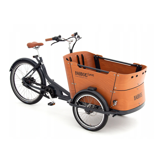
Babboe Curve Assembly & Instruction Manual
Hide thumbs
Also See for Curve:
- Assembly instructions manual (156 pages) ,
- Instruction manual (12 pages) ,
- Maintenance (3 pages)

Related Manuals for Babboe Curve


Summary of Contents for Babboe Curve
- Page 1 Babboe website...
- Page 2 Contents Intro Inspecti on Warnings Inspecti on Box I, II and III Inspecti on Tools and Instructi ons Step 1: Att aching the fenders Step 2: Mounti ng the front wheels Step 3: Connecti ng the front and rear frame Step 4: Att aching the steering damper Step 5.1:...
-
Page 3: Intro
Soon you will be able to enjoy riding your Babboe Curve! This manual also provides informati on about the use of the Babboe Curve bike and the warranty. -
Page 4: Inspecti On Warnings
Curve cargo bike, please contact your local Babboe distributor. Contact details can be found on www.bakfietsen.com. If you do not find the right contact details, please contact Babboe in the Netherlands via service@babboe.nl or give us a call on +31.33.7410742. - Page 5 Inspect the contents of boxes I, II and III. Note: The contents of the boxes have been carefully determined. Should any parts be missing aft er all, please contact Babboe’s Customer Service department. Box I contents (hwwx-991) Box II contents (hwwx-990) •...
- Page 6 Inspecti on Tools and Instructi ons Tools needed Ring/open-ended spanners # 8-10-11-13-15-30 Philips screwdriver (Philips 3) Allen keys 5-6 mm Bahco/ Adjustable spanner (opti onal) Important! A simple, light-duty tool set comes with the cargo bike in the event that you do not have the required tools at your disposal (except for the Philips screwdriver or the Bahco key).
- Page 7 Step 1: Att aching the fenders Parts needed: Tools needed: - 2x fenders (Box I) - Philips screwdriver - 2x steps to be mounted on the fenders (Box I) - Front frame (Box I) - Sachet A (4x M5 bolts, 4x M5 spring washers, 4x M5 washers, 2x M6 bolts, 2x M6 spring washers, 2x M6 washers) Get the front frame and fenders out of the box and remove the protecti ve packaging and materials.
- Page 8 Step 2: Mounti ng the front wheels Parts needed: Tools needed: - 2x front wheels (20-inch) (Box I) - Open-end spanner # 15 Remove the two nuts/washers from the wheel axle. You will need these again soon, so keep them at hand. Gently place the front frame on its side.
- Page 9 Screw the nuts back into the wheel axle. Use an open-end spanner to ti ghtly secure the nuts (see detail picture D). Repeat the previous steps for the other wheel.
- Page 10 Step 3: Connecti ng the front and rear frame Parts needed: Tools needed: - The rear frame (Box II) - Open-end spanner # 30 / - The front frame Bahco / adjustable spanner Note: Ask for assistance from someone for this step. It will be a lot easier if you do. Get the rear frame out of the box and remove the protecti ve packaging materials.
- Page 11 Slide the att achment piece over the cylinder onto the front frame as shown in Figure 5. Then place the washers (5) between the att achment piece (1) and the cylinder (2) as shown in Figures 6 and 7. Then re-insert the bolt (3) through the att achment piece and the cylinder.
- Page 12 Step 4: Att aching the steering damper Tools needed: - Open-end spanner # 13 - Allen key # 6 This step involves att achment of the steering dampers. These are already pre- mounted onto the rear frame (see Figure 8). Remove the specifi...
- Page 13 Step 5.1: Mounti ng the steering tube Parts needed: Tools needed: - Sachet B (2x M8 bolts, 2x M8 lock nuts, 4x M8 washers) - Open-end spanner # 13 - Allen key # 5 The steering tube is mounted onto the front frame during this step. The steering tube is already connected to the rear frame by means of the gear and brake cable.
- Page 14 Step 5.2: Securing the steering stem Tools needed: - Allen keys # 5 and 6 The stem is already inserted into the steering tube, but sti ll has to be adjusted and secured into the correct positi on. Tip: Only adjust the positi on of the steering stem loosely at this point; you will determine the defi...
- Page 15 If you want to adjust the angle of the stem, unti ghten the two hex bolts at the front of the steering pin using Allen key # 6 (see Figure 12). Set the stem to the desired positi on and then reti ghten the hex bolts.
- Page 16 Step 5.3: Att aching the saddle Parts needed: Tools needed: - Open-end spanner # 13 - Saddle and saddle pin - Allen key # 5 Important! Adhere to the specifi ed order of sub-steps for this part of the assembly. If you att ach the saddle pin fi rst, you run the risk of the saddle pin falling down into the saddle tube.
- Page 17 Step 6: Att aching the brake cables The front brake cables are the only cables that have not been fully pre-mounted. These cables have been pre-mounted onto the steering stem (handlebars), but sti ll have to be att ached at the wheels. First, guide a cable from the left brake lever on the handlebars via the guide points on the left side of the steering tube and the underside of the front frame (indicated with arrows in Figure 15) to the left front wheel.
- Page 18 Insert the cap on the end of the steel brake cable into the upper brake lever, as shown in Figures 16 and 17. Place the brake cable into the groove of the brake (indicated with arrows in Fig. 18).
- Page 19 Next, hook the cable around the noodle (indicated with an arrow in Fig. 19). Then lift the lower lever up to att ach the last adjustment clamp there (see Fig. 20). The brake cable is now installed (see Fig. 21). Repeat these steps for the right front wheel and the right brake cable.
- Page 20 Step 7.1: Att aching the bott om plate Parts needed: Tools needed: - Bott om plate (found in the bott om of Box III) - Open-end spanner # 10 - Sachet C (4x M6 bolts, 4x M6 cap nuts, 4x M6 spring washers, - Philips screwdriver 8x M6 washers) Step 7 involves mounti ng the cargo box.
- Page 21 Step 7.2: Att aching the rear panel Parts needed: Tools needed: - Two steel plates for att achment of rear panel to the steering - Open-end spanner # 10 tube - Philips screwdriver - Rear panel (large curved panel with cord holes, found in Box III) - Sachet D (4x M6 Philips-head bolts, 4x M6 cap nuts, 4x M6 spring washers, 8x M6 washers) Place the rear panel of the cargo box against the steering tube, as shown in Figure 23.
- Page 22 Step 7.3: Att aching the connecti on profi les (rear) Parts needed: Tools needed: - Open-end spanner # 10 - 2x connecti on profi les (the longest steel profi les in Box II) - Philips screwdriver - Sachet E (2x M6 bolts (short), 4x M6 bolts (long), 6x M6 cap nuts, 6x M6 spring washers, 12x M6 washers, 2x tube pieces) Att ach both connecti on profi...
- Page 23 Step 7.4: Att aching the side panels Parts needed: Tools needed: - 2x side panels - Open-end spanner # 10 - Sachet F (4x M6 bolts, 4x M6 cap nuts, 4x M6 spring washers, - Philips screwdriver 8x M6 washers, 2x tube pieces) Important! When att aching the side panels, make sure that the labelling on the side panels is on the outside of the cargo box.
- Page 24 Step 7.5: Att aching the steps to the side panels Parts needed: Tools needed: - Philips screwdriver - Sachet G (4x M6 bolts, 4x M6 spring washers, 4x M6 washers) The steps on the fenders must be connected to the side panels. Screw both side panels onto the steps using two bolts and washers (see Figure 26).
- Page 25 Step 7.6: Att aching the connecti on profi les (front) Parts needed: Tools needed: - 2x connecti on profi les (shortest steel profi les in Box II) - Open-end spanner # 10 - Sachet H (4x M6 bolts, 4x M6 cap nuts, 4x M6 spring washers, - Philips screwdriver 8x M6 washers, 2x tube pieces) Att ach both connecti on profi...
- Page 26 Step 7.7: Att aching the bott om secti on of the front panel Parts needed: Tools needed: - Open-end spanner # 10 - Bott om secti on of front panel (printed part) (Box III) - Philips screwdriver - Sachet I (2x M6 bolts (long), 3x M6 bolt (short), 5x M6 cap nuts, 5x M6 spring washers, 10x M6 washers, 2x plasti c washers) - Rubber strip (Box II)
- Page 27 Tip: If you also have a rain tent, retrieve the instructi on manual for it and perform the steps for att achment of the rain tent now. It will be a lot easier to do this at this stage than aft er the cargo bike is completely assembled. Att ach the bott om secti on of the front panel to the subframe using a short bolt (see Figure 28 and detail picture S), placing the two plasti c washers (1) between the front panel and the connecti on point of the subframe.
- Page 28 Step 7.8: Att aching the top secti on of the front panel Parts needed: Tools needed: - Open-end spanner # 10 - Top secti on of front panel (Box III) - Philips screwdriver - Sachet J (4x M6 bolts, 4x M6 cap nuts, 4x M6 spring washers, 8x M6 washers) Att ach the top secti on of the front panel to the connecti on profi...
- Page 29 Step 8.1: Installing the cargo box seats Parts needed: Tools needed: - Holders for seats at the front and rear of cargo box (in Box II) - Open-end spanner # 10 - 2x seats (identi cal) (Box III) - Philips screwdriver - Sachet L (3x M6 bolts (short), 1x M6 bolt (long), 4x M6 cap nuts, 4x M6 spring washers, 8x M6 washers) Att ach the holder for the front seat to the bott om secti on of the front panel...
- Page 30 Next, att ach the holder for the rear seat using the two short bolts, as shown in detail picture W.
- Page 31 Slide the front and rear seats along the guides in the connecti on profi les (see Figure 34) and securely “click” the seats into place on the mounted holders. (see detail picture X).
- Page 32 Step 8.2: Att aching the seat belts Parts needed: Tools needed: - Open-end spanner # 10 - 4 sets of 3-point seat belts - Philips screwdriver - Sachet M (4x M6 bolts, 4x M6 cap nuts, 4x M6 spring washers, 8x M6 washers) -Sachet N (8x rubber rectangle) Pull the buckles at the ends of the seat belt through a rubber rectangle from...
- Page 33 Step 8.3: Att aching the bars inside the cargo box Parts needed: Tools needed: - 2x bars, (Box I) - Open-end spanner # 10 - Sachet K (4x M6 bolts, 4x M6 cap nuts, 4x M6 spring washers, - Philips screwdriver 8x M6 washers) Att ach both bars using the nuts, bolts and washers from sachet K in the unused holes of the side panels in the cargo box, as illustrated in Figure 37...
- Page 34 Step 9: Att aching the pedals Parts needed: Tools needed: - Open-end spanner # 15 - Left pedal (marked “L”) (Box II) - Right pedal (marked “R”) (Box II) Tighten the axle of the right pedal (clockwise) in the crank using open-end spanner # 15 (see detail picture AD).
- Page 35 Step 10: Att aching the front lights Parts needed: - 2 front lights (Box II) The delivered front lights must be att ached underneath the steps at the front of the cargo box. Slide the clamp of the light over the secti on of frame tubing under the step, as illustrated in Figure 39.
- Page 36 - Lock Note: This step only applies if you received the lock separately. Important! To protect the fi nish of your Babboe Curve cargo bike, we recommend that you apply masking tape or something similar to the fender at vulnerable locati ons.
-
Page 37: Tips For Use
Babboe Curve cargo bike will feel as you ride it. Lights The Babboe Curve cargo bike is equipped with LED lighti ng on batt eries both at the front and rear of the bike. The front lights are operated by means of a butt on on top of the lights, through the hole at the front of the cargo box’s steps. -
Page 38: Warranty
Frame number Should you need a frame number for insurance purposes, the frame number of your Babboe Curve cargo bike can be found on the underside of the frame near the pedals, on the curve of the bott om bracket. -
Page 39: Maintenance History
Curve cargo bike, please contact your local Babboe distributor. Contact details can be found on www.bakfietsen.com. If you do not find the right contact details, please contact Babboe in the Netherlands via service@babboe.nl or give us a call on +31.33.7410742.
Need help?
Do you have a question about the Curve and is the answer not in the manual?
Questions and answers