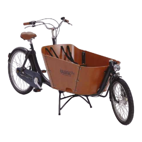
Babboe City Assembly Manual
Cargo bike
Hide thumbs
Also See for City:
- Assembly instructions manual (154 pages) ,
- Instruction manual (7 pages) ,
- Maintenance (3 pages)

Related Manuals for Babboe City


Summary of Contents for Babboe City
- Page 1 Babboe BV – Saljoet 3 – 3824 MD Amersfoort, The Netherlands – info@babboe.nl – Tel: +31(0)33-7410740...
- Page 2 Intro will assist you in the assembly of your new Babboe City. Check the contents of the boxes, make sure that you have the right tools at hand and carefully use the Babboe City as well as about the warranty.
- Page 3 If the steps in this manual are followed, the complete warranty as shown on the website (www.lastcykel.se/kundservice) will be applicable. The correct assembly of the cargo bike is of crucial importance and falls outside of the responsibility of Babboe. As such, Babboe shall accept therefrom.
- Page 4 Check the contents of box I, II and III. Note: The contents of your package have been carefully selected and packed. If, however, you notice that parts are missing, please get in touch with Babboe. Box I contents (hwwx-702) Box II contents (hwwx-701)
-
Page 5: Tools Required
Check Tools and Notes Tools required: General note In order to indicate the order of assembly for bolts, nuts, rings etc., this manual will contain figures like the one shown below. Ring/open-ended spanners 10-11-13-15 Bolt Washer Hex keys 4-5-6 mm Wood Steel Washer... - Page 6 STEP 1 Mounting the beam Parts and tools required: - Sachet I - Hex key 6mm - Front and rear frame - Ring/open-ended spanner #13 1. Start with the front frame from box I. First remove the black protective covers on the axle of the front wheel. 2.
- Page 7 STEP 2 Mounting the kickstand Parts and tools required: - Sachet I - Hex key 6mm - Front frame and kickstand - Ring/open-ended spanner #13 1. Place the kickstand onto the rear cross beam of the front frame (see picture). 2.
-
Page 8: Mounting The Frame
STEP 3 Mounting the frame Parts and tools required: - Sachet J - Hex key 6mm - Front and rear frame - Ring/open-ended spanner #13 1. Extend the kickstand, the front frame can now stand on its own. 2. Slide the tube of the rear frame into the front frame tube. 3. - Page 9 3. Connect the two tube elements by using the 2 long bolts from sachet J. Secure the section underneath using the short bolts from the same sachet. 4. Firmly tighten the bolts with a 6mm hex key on the one side, and use the #13 spanner for the other side.
- Page 10 STEP 4.1 Mounting the steering stem Tools required: - Hex key 5mm and 6mm 1. Remove the protective caps from the steering stem (top and underside). 2. Also remove the protective cap on the end of the steering pin (the extension of the steering arch). 3.
-
Page 11: Adjusting The Handlebar Angle
STEP 4.2 Adjusting the handlebar angle Tools required: - Hex key 6mm 1. If you want to adjust the angle of the handlebars, screw open the steering pin. 2. Place the handlebars in the desired position. Then retighten the steering pin. -
Page 12: Mounting The Saddle
STEP 5 Mounting the saddle Parts and tools required: - Saddle and saddle post - Hex key 4mm - Ring/open-ended spanner #13 1. Slide the saddle post into the saddle 2. Place the saddle in the desired position. Tighten the bolt firmly using the #13 spanner. - Page 13 3. Position the saddle above the saddle stem and insert the saddle post into it. IMPORTANT: Never insert a saddle post into the stem that is not attached to the saddle. 4. Tighten the saddle into place by using the hex key on the hex bolt on the saddle stem.
-
Page 14: Mounting The Pedals
STEP 6 Mounting the pedals Tools required: - Ring/open-ended spanner #15 Mount the pedals using spanner #15. Place the left pedal (L) on the left side as illustrated in the picture, and the right pedal on the right side (as seen from a sitting position on the bike). - Page 15 STEP 7 Mounting the steering rod Parts and tools required: - Steering rod - Ring spanner #13 - Open-ended spanner #11 1. The handlebars are operated by means of a steering rod extending from point B to point A. This rod will already be fitted with nuts and bolts. 2.
- Page 16 4. Make sure that the nuts at points A and B are tightly secured. If necessary, tighten the nuts more firmly using spanner #13.
- Page 17 STEP 8 Mounting the brake cable Tools required: - Ring/open-ended spanner #10 1. The cable for the front brake is the only cable that is not yet fully mounted. It is already attached to the Roller Brake (drum brake) in the front wheel. Check to make sure that this is the case.
- Page 18 4. Next, pull the cable through the feed and squeeze the handbrake. Then place the end of the cable in the corresponding clamp on the handbrake. 5. Check to make sure that the front brake is properly adjusted. If this is not the case, adjust the feed nut on the handbrake or the drum brake on the front wheel.
- Page 19 STEP 9.1 Mounting the bottom panel Required parts and tools: - Bottom panel - Sachet B - Phillips screwdriver Step 9 involves mounting the cargo box. This step is divided into a number of sub-steps. 1. Place the bottom panel on the frame’s cross beams. 2.
- Page 20 3. Now gently place the bike on its side, with the kickstand extended so the bike is supported by it. 4. Then mount the other two bolts and washers from sachet B. Secure these tightly. 5. Then turn the cargo bike straight up onto its kickstand.
-
Page 21: Mounting The Rear Panel
STEP 9.2 Mounting the rear panel Required parts and tools: - Rear panel - Ring/open-ended - Sachet C spanner #10 - Black sleeve caps - Phillips screwdriver Place the rear panel of the cargo box (which includes holes for the cords) securely using the parts from sachet C and the black sleeve caps. -
Page 22: Mounting The Front Panel
STEP 9.3 Mounting the front panel Parts and tools required: - Front panel - Sachet A - Phillips screwdriver Now attach the front panel of the cargo box to the frame, near the front wheel, using the parts from sachet A. TIP: It is somewhat difficult to attach the rear panel due to the awkward position. -
Page 23: Mounting The Side Panels
STEP 9.4 Mounting the side panels Parts and tools required: - 2 side panels - Phillips screwdriver - 4 attachment profiles - Ring/open-ended - Sachets D, E & F spanner #10 Overview The contents of the sachets labeled D, E and F are required for the assembly of sides of the cargo box. - Page 24 In this step, the attachment profiles are mounted first. Each of these 4 profiles fits specifically (only) in its intended spot and are attached on the inside of the box. 1. Attach the 2 longer attachment profiles to the rear panel (closest to the handlebars) using the contents of sachet D.
- Page 25 1. Now place the side panels of the cargo box up against the attachment profiles that you just attached. 2. Connect the flat side panels to the attachment profiles using the remaining contents of sachet D (see the overview on page 22). 3.
- Page 26 4. Now use the parts from sachet F to connect the remaining (2) points of the profiles to the side panels. These 2 connections will accommodate the seat later on. The corner profiles (provided separately in an unlabeled bag) must also be connected during this step (see picture).
- Page 27 STEP 9.5 Securing the cargo box Parts and tools required: - Sachet H - Phillips screwdriver - Ring/open-ended spanner #10 1. Connect the side panels at the 8 different connection points to the bottom planel using a bolt, washer and nut from sachet H for each point. Make sure to adhere to the correct order for connection.
- Page 28 STEP 9.6 Mounting the cargo box seat Parts and tools required: - Sachet G - Phillips screwdriver - Ring/open-ended spanner #10 1. Install the cargo box seat from above onto the two corner profiles attached to the side panels and the bolts protruding from the rear panel. 2.
- Page 29 STEP 10 Mounting the cords Parts and tools required: - Remainder of sachet G - Ring/open-ended - Two cords spanner #10 - Phillips screwdriver - Black caps 1. Pull the buckle on the end of the cord through the holes in the rear panel.
-
Page 30: Mounting The Lock
If necessary, let some air out of the tires in order to make it fit around the wheel. IMPORTANT: To protect the finish of your Babboe City bike, we recommend that you apply masking tape or something similar to the mudguard. -
Page 31: Tips For Use
Extending the kickstand To support the Babboe City cargo bike on its kickstand, first stand next to the bike near the handlebars. Turn the handlebars away from you to create room. -
Page 32: Warranty And Maintenance
Frame number: Should you need a frame number for insurance purposes, the frame number of your Babboe City cargo bike can be found on the underside of the frame Maintenance: Even though the Babboe City cargo bike is constructed from high-quality components, maintenance is nevertheless important. - Page 33 Frame number: Date of purchase: Babboe order number: Date: Performed by: not hesitate to contact Babboe’s Customer Service team: Email: info@lastcykel.se Tel: +46(0)76-8248171 (on weekdays from 9:00AM to 5:00PM Or go to our Customer Service page on our website www.lastcykel.se...
Need help?
Do you have a question about the City and is the answer not in the manual?
Questions and answers