
Related Manuals for Iron & Oak BHH2013GX


Summary of Contents for Iron & Oak BHH2013GX
-
Page 1: Log Splitter
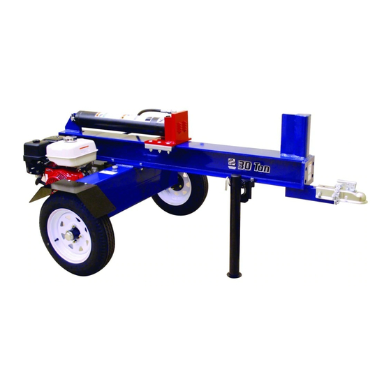
MBHH2013C Model: BHH2013GX BHH3013GX BHH3013GXF Iron & Oak 20 and 30 Ton Horizontal Log Splitter Model BHH2013 and BHH3013 Owner / Operator and Safety Manual... - Page 3 Initial Start-up Instructions ❏ Read all assembly, operating, and safety instructions. ❏ Complete and return the warranty card to register your log splitter. ❏ Write the serial number and date-of-purchase in this manual. ❏ Assemble the log splitter. ❏ Make sure the oil filter is properly installed. (See “Assembly Procedure”...
-
Page 4: Table Of Contents
Contents Introduction ............4 Safety . - Page 5 WARNING To avoid personal injury or death, carefully read and understand all instructions pertaining to the Iron & Oak Commercial Products’ log splitter. Do not attempt to assemble, operate, or maintain our product without fully understanding all our instructions and safety precautions. Do not operate the log splitter unless you read and understand the instructions and warnings in this manual.
-
Page 6: Introduction
Introduction The commercial BHH2013 and BHH3013 Horizontal Log Splitters are designed for tough applications. With 20 or 30 tons of splitting force, a 12 second cycle time, and a 6.5 or 11 HP engine, the BHH2013 or BHH3013 will handle most of your commercial log splitting needs. -
Page 7: Worksite Safety
Worksite Safety ✔ To avoid tripping, do not leave tools, logs, or other components laying around the work area. ✘ NEVER operate your log splitter on slippery, wet, muddy, or icy surfaces. The location you choose should be flat, dry, and free from any tall grass, brush, or other interferences. -
Page 8: Log Splitting Safety
✘ Do not, under any circumstances, alter your log splitter. This equipment was designed and engineered to be used in accordance with the operating instructions. Altering the equipment, or using the equipment in such a way as to circumvent its design capabilities and capacities, could result in serious or fatal injury and WlLL VOID THE WARRANTY. -
Page 9: Towing
✔ ALWAYS check the oil level in the hydraulic oil tank and engine reservoir. ✘ NEVER operate your log splitter when it is in need of repair or is in poor mechanical condition. ✘ NEVER tamper with the engine to run it at excessive speeds. The maximum engine speed is preset and is within safety limits. -
Page 10: Refueling
Refueling ✔ ONLY refuel the log splitter outdoors in a clear area void of gas fumes or spilled gasoline. ✔ ALWAYS use an approved fuel container to carry gasoline. ✔ ALWAYS replace the log splitter gas cap and the fuel container cap securely. ✔... -
Page 11: Assembly Instructions
Assembly Instructions Required Tools • 10” crescent wrench • Two 1/2’’ open end wrenches • Two 3/4” open end wrenches • Funnel • Pliers • Band cutters Shipping List The following chart contains the list of parts that should be shipped as part of the BHH2013 or BHH3013 Log Splitter. -
Page 12: Unpacking The Crate
Unpacking the Crate 1. Cut the metal banding and remove the top, sides, ends, protective plastic covering of the packing crate. Do not remove the base unit or the rail assembly from the bottom pallet at this time. 2. Carefully check the larger components on the shipping pallet for damage. -
Page 13: Assembly Procedure
Assembly Procedure CAUTION Some components are very heavy and can be damaged if mishandled. Also, to help prevent personal injury, it is strongly recommended that two (2) people work together to uncrate and assemble the log splitter. Remove and read the instructions and safety recommendations before assembling or operating this log splitter. - Page 14 4. Position wooden blocking under the engine mounting plate to level and support the base unit. 5. Using two (2) people or a lifting device, remove the rail assembly from the pallet. Important Notice Attach the lifting device, as shown, in a way that will not damage any component parts of the log splitter, such as the cylinder or the valve.
- Page 15 7. Bolt the base unit to the rail assembly using four 1/2-13 x 1-1/2 inch long hex head bolts, lockwashers, and nuts, as shown. Tighten the nuts securely. 8. Bolt the jack leg assembly to the rail assembly using three 1/2-13 x 1-1/2 inch long hex head bolts, lockwashers, and nuts, as shown.
- Page 16 11. Install the valve link onto the valve body, as shown, using a 1/4 x 1 inch long clevis pin. Secure the clevis pin with a cotter pin (bend the ends of the cotter pin to make it secure). 12. Install the valve handle onto the valve link using a 1/4 x 3/4 inch long clevis pin.
- Page 17 15. Attach the other high-pressure hose from the pump to the bottom of the valve. Securely tighten the hose fitting. NOTE: The high-pressure hose is self- sealing and does not require any type of sealing material. Tighten the fitting with a 10 inch crescent wrench.
-
Page 18: Start-Up Procedure
Start-up Procedure Important Notice Do not start the engine. Follow all the instructions in the “Start-up Procedure” before operating the log splitter. Failure to follow this recommendation will result in engine and hydraulic pump damage. If this log splitter is purchased without an engine, the customer assumes all liabilities that might arise from an engine that is incompatible with the design of the log splitter. - Page 19 5. Push the valve control handle with one hand to the forward (extend) position (towards the splitting wedge), and pull the engine starter cord with the other hand (approximately 15 times) until the cylinder piston moves forward. (Keep everything away from the pusher plate and wedge during this step). Cylinder Extend Cylinder Retract NOTE: Extending the cylinder piston draws the hydraulic fluid through the system and...
-
Page 20: Towing
Towing WARNING Maximum Speed Limit — 35 mph Your log splitter is built on a solid, unsuspended axle. To prevent damage or possible loss of vehicle control, use extreme caution when towing and do not exceed a vehicle speed of 35 mph, especially when driving on a bumpy road. 1. - Page 21 4. Place a customer supplied lock or lock pin into the latch assembly of the hitch. WARNING Making sure the log splitter is securely attached to the vehicle is the responsibility of the owner/operator. Failure to securely attach the log splitter can cause loss of control of the vehicle or the log splitter being separated from the towing vehicle, resulting in serious injury or death.
-
Page 22: Operation
Operation WARNING Do not attempt to operate the log splitter without fully understanding all our instructions, safety precautions, and/or warnings. If any doubt or question arises about the correct or safe method of performing any- thing found in this or other Iron & Oak Products’ manuals, contact your Iron &... - Page 23 WARNING Before loading and operating the log splitter, put on the proper protective gear such as safety goggles, face shield, hearing protec- tion, tight-fitting gloves (without drawstrings or loose cuffs), and steel-toed shoes. 3. Start the engine using the instructions from the engine manual.
- Page 24 b. Only using your hand, push the control lever forward (towards the log). If the log moves before it is contacted by the pusher plate, release the control lever and then reposition the log. Operate the log splitter only when standing in the safe operating area, as shown in the picture.
- Page 25 c. Hold the control lever, extending the splitting wedge, until the log is split or the cylinder rod stops at its maximum travel position. Stop the log splitter (forward movement) at any point in the splitting process, if you feel an unsafe log splitting condition is occurring.
-
Page 26: Inspection And Maintenance
Inspection and Maintenance General Maintenance Check (before operating) The hydraulic system (hoses, cylinder, and pump) should be carefully inspected before each use. Also, inspect the mechanical parts at the same time. Make sure all clamps, nuts, bolts, fittings, etc. are properly installed and tightened. WARNING Do not check for leaks with your hand. - Page 27 Notes 800-817-1005 Iron &...
-
Page 28: Hydraulic Oil Change
Hydraulic Oil Change Iron & Oak Commercial Products recommends an oil and filter change every 100 hours of operation. Refer to the “Specifications” section in this manual for the type and quantity of oil. Important Notice Never run the log splitter unless the hydraulic oil tank is full. 1. - Page 29 4. Refill the hydraulic tank. a. Reconnect inlet hose (2) to the pump. b. Remove the hydraulic tank fill cap and fill the tank with the recommended type and quantity of oil. Replace the cap. 5. Drain and refill the piston end of the cylinder.
-
Page 30: Specifications
Specifications Mechanical Specifications Slide Rail ......6 x 6 inch reinforced, heavy-duty H-beam Wedge ......9”, High carbon steel, compound angle Force/Tonnage . -
Page 31: Troubleshooting
Troubleshooting The following section details procedures for checking your log splitter, should you encounter a malfunction. We recommend that you do not attempt to make repairs to the log splitter. In the long run, it is better to take your log splitter to a servicing lawn and garden dealer for repairs. -
Page 32: Decals
Decals Make sure all decals are attached to the log splitter and/or engine and are legible at all times. Item Part No. Description Qty. BR002652 Decal, Notice BR002653 Decal, Maximum Speed BR002621 Decal, Flag BR002521 Decal, Serial Number 777890 Decal, Warning Fire Hazard 787944 Decal, Warning Pinch Point BR002308 Decal Kit, Standard Models BR002311 Decal, Warning Towing Safety BR002310 Decal, Warning Crush Injury 786635... - Page 33 (10) (12) (11) 800-817-1005 Iron & Oak...
-
Page 34: Parts
Item Part No. Description Unit 1 1 BR02125711 Weldment, Base Tank All 2 2 BR008301B Seal, Inside All 3 4 BR008301A Bearing, Tapered Roller All 4 2 BR008317 Hub, Studded All 5 2 BR008311 Tire, 4.8” x 12” All 6 2 778844 Washer, Thrust All 7 2 BR008301F Key, Cotter, 1/8 x 2” long All 8 2 ... - Page 35 800-817-1005 Iron & Oak...
- Page 36 Item Part No. Description Unit 1 BR02125610 Weldment, Rail 2 82509 Nut, 1/2‐13 3 82519 Lockwasher, 1/2” 4 82493 Bolt, 1/2‐13 x 1‐1/2” long 5 BR013104 Retainer, Slide 791636 Slide Guide Spacer (thin part) 6 All BR013102 Guide, Slide (thick part) 7 82499 Bolt, Carriage, 1/2‐13 x 2‐1/2” 8 BR02125803 Weldment, Slide Plate 9 82492 Bolt, 1/2‐13 x 3” long 10 783948 Safety Quick‐Link 11 1130 Chain Assembly 12 ...
- Page 37 800-817-1005 Iron & Oak...
- Page 38 BR002001H Pump, Hydraulic 2013 Qty 11 1 m Part No. Description Unit BR002002B Pump, Hydraulic 3013 12 4 GX160 Honda GX160 2013 82086 Bolt, 5/16‐24 x 3/4” long All 1 1 13 1 GX270 Honda GX270 3013 BR001112 Casting, Head Filter All 14 1 82522 Key, Engine Shaft 2012 BR001113 Element, Filter All 2 1 ...
- Page 39 IO2030-C...
-
Page 40: Warranty
Warranty For one year from the date of purchase, Iron & Oak Commercial Products Inc. will replace for the original purchaser, or repair free of charge, all parts of the Iron & Oak Commercial Products’ Hydraulic Log Splitter, returned to our factory PREPAID and found upon inspection by us to be faulty, due to defects in materials or workmanship. -
Page 41: Warranty Card
Important Warranty Information To activate your Iron & Oak log splitter warranty, Iron & Oak Commercial Products, Inc. please fill out the information in the form below and mail 20195 S. Diamond Lk. Rd. STE 100 in an envelope to the address listed on the right or Rogers, MN 55374 go online to www.ironandoak.com Iron &... -
Page 43: Optional Attachment
Optional Attachment 4-Way Wedge Assembly (Part No. BR021270-Kit) 4-Way Wedge Assembly Item Part No. Description Qty. BR021270 Wedge Weldment BR021271 Post Weldment BR001255 Bolt, 3/4-10 x 2-1/2” BR001425 Locknut, 3/4-10 5 (NS) BR020264 Spacer, 2-1/2” 6 (NS) BR020265 Spacer, 3-1/2” NS - Not Shown Safety Flag Kit (Part No. - Page 44 Iron & Oak Commercial Products, Inc. 20195 S. Diamond Lk Rd, STE 100 Rogers, MN 55374 Phone: 800-817-1005 (Toll Free) Fax: 866-779-9963 E-mail: sales@ironandoak.com Web Site: www.ironandoak.com BHH2013-BHH3013 11-13...
Need help?
Do you have a question about the BHH2013GX and is the answer not in the manual?
Questions and answers