Table of Contents
Advertisement
RETAIN THESE INSTRUCTIONS
FOR FUTURE REFERENCE
IMPORTANT
The Clean Air Act of 1990 bans the intentional venting of
refrigerant (CFCs, HCFCs AND HFCs) as of July 1,
1992. Approved methods of recovery, recycling or
reclaiming must be followed. Fines and/or incarceration
may be levied for noncompliance.
WARNING
This product and/or the indoor unit it is matched with may
contain fiberglass wool.
Disturbing
the
insulation
maintenance, or repair will expose you to fiberglass wool
dust. Breathing this may cause lung cancer. (Fiberglass
wool is known to the State of California to cause cancer.)
Fiberglass wool may also cause respiratory, skin, and
eye irritation.
To reduce exposure to this substance or for further
information, consult material safety data sheets.
WARNING
Improper installation, adjustment, alteration, service or
maintenance can cause personal injury, loss of life, or
damage to property.
Installation and service must be performed by a licensed
professional installer (or equivalent) or a service agency.
during
installation,
INSTALLATION
INSTRUCTIONS
T-CLASSt TPA Series
7.5 AND 10 TON
HEAT PUMPS
7.5 TO 10 TONS
506148-01
12/2015
Supersedes 10/2011
Table of Contents
. . . . . . . . . . . . . . . . . . . . . . . . . . . . . . . . . .
. . . . . . . . . . . . . . . . . . . . . . . . . . . . . . . . . . . . .
. . . . . . . . . . . . . . . . . . . . . . . . .
. . . . . . . . . . . . . . . . . . . . . . . . . . . . . . . . . . . . . .
. . . . . . . . . . . . . . . . . . . . . . . . . . . . .
. . . . . . . . . . . . . . . . . . . . . . . . . . . . . . .
. . . . . . . . . . . . . . . . . . . . . . . . . .
. . . . . . . . . . . . . . . . . . . . . . . . . . . . . . . . . .
Shipping and Packing List
Check the unit for shipping damage and listed times below
are intact. If damaged, or if parts are missing, immediately
contact the last shipping carrier.
1 - Assembled outdoor unit
1 - Installation instruction
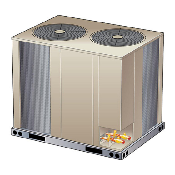
Outdoor Unit
TPA series heat pumps, which will also be referred to in this
instruction as the outdoor unit, uses HFC-410A
refrigerant. This outdoor unit must be installed with a
matching indoor unit and line set as outlined in the TP
Engineering Handbook.
This outdoor unit is designed for use in thermal expansion
valve (TXV) systems only.
Litho U.S.A.
. . . . . . . . . . . . . . . . . . . . . .
. . . . . . . . . . . . . . .
. . . . . . .
. . . . . . . . . . . . . . . . . . . .
. . . . . . . . . . . . . . . . . . . . . .
. . . . . . . . . . . . . . . . . .
. . . . . . . . . . . . .
1
1
2
3
4
4
4
5
5
8
11
11
11
12
13
Advertisement
Table of Contents

Related Manuals for Lennox T-Class TPA090S4S


Summary of Contents for Lennox T-Class TPA090S4S
-
Page 1: Table Of Contents
INSTALLATION INSTRUCTIONS T-CLASSt TPA Series 7.5 AND 10 TON HEAT PUMPS 7.5 TO 10 TONS 506148-01 Litho U.S.A. 12/2015 Supersedes 10/2011 Table of Contents Shipping and Packing List ..... . Outdoor Unit . -
Page 2: Unit Dimensions, Corner Weights And Center Of Gravities
Unit Dimensions, Corner Weights and Center of Gravities Corner Weights Center of Gravities Model No. Model No. lbs. lbs. lbs. lbs. inch inch 21.75 29.0 TPA090S4S TPA090S4S 20.0 28.25 TPA120S4S TPA120S4S OPTIONAL HAIL GUARD (Field Installed All Coil Sides) (Not used with Coil Guard) INLET AIR OUTDOOR FAN GUARDS... -
Page 3: Unit Plumbing Parts Arrangement
Unit Plumbing Parts Arrangement TPA090S4S DEFROST SWITCH LOCATION (S6) CHECK EXPANSIVE VALVE (CTXV) REVERSING VALVE HIGH PRESSURE SWITCH (S4) COIL LOSS-OF-CHARGE SWITCH (S24) COMPRESSOR CTXV SENSING BULB SUCTION LINE SERVICE VALVE LIQUID LINE SERVICE LIQUID LINE BI-FLOW DRIER VALVE TPA120S4S HIGH PRESSURE SWITCH (S4) DEFROST SWITCH... -
Page 4: Unit Control Box Components Arrangement
Unit Control Box Components Arrangement TPA090S4S AND TPA120S4S DEFROST CONTROL TRANSFORMER BOARD (T1) RELAY (K149) TERMINAL STRIP (TB14) RELAY (K10) CONTACTOR (K1) RUN CAPACITORS (C1, C2,) GROUND LUG Model Number Identification T P A 120 S Brand/Family Voltage Y = 208/230V‐3 phase‐60hz T = T-Class™... -
Page 5: Installation Clearances
See Unit Dimensions on page to sizing mounting slab, fittings). Size refrigerant lines greater than 50 linear feet platforms or supports. Refer to figure 2 for mandatory (15m or greater) according to the Lennox Refrigerant installation clearance requirements. Piping Design and Fabrication Guidelines (Corp. 9351-L9) NOTES: or latest version. -
Page 6: Typical Control Wiring
CIRCUIT SIZING AND DISCONNECT SWITCH TYPICAL HIGH VOLTAGE POWER SUPPLY CONNECTIONS MAIN FUSE BOX/BREAKER CONTROL BOX PANEL DISCONNECT SWITCH USE THE LEFT CUTOUT TO ROUTE HIGH VOLTAGE WIRING TO THE K1 CONTACTOR ON THE TPA 090S AND 120S MODELS. K1 CONTACTOR GROUND LUG LEFT CUTOUT NOTE —... - Page 7 Figure 3. TPA090S4S and TPA120S4S G, J, M, and Y Voltages) Typical Wiring Diagram Page 7 TP SERIES...
-
Page 8: Refrigerant Charge And Check
If line set is less than 25 feet, subtract this due to differences in installations. Significant amount from each circuit. Refer to Lennox Refrigerant differences could mean that the system is not properly Piping Design and Fabrication Guidelines for more charged or that a problem exists with some information. - Page 9 Table 3. HFC-410A Approach Temperatures 3. Do not use the approach method if system pressures do not match pressures in tables 4 or 5 except when Approach Approach ºF the outdoor ambient temperature is below 65 Temperature (5F) Temperature (5C) Stage Models (+/- 1)
- Page 10 Table 6. HFC-410A Temperature (°F) - Pressure (Psig) °F Psig °F Psig °F Psig °F Psig °F Psig °F Psig °F Psig °F Psig 100.8 137.1 178.5 231.6 290.8 365.0 545.6 445.9 102.9 139.6 181.6 235.3 295.1 370.0 451.8 552.3 105.0 142.2 184.3...
-
Page 11: System Operation
If the timing selector jumper is missing, the defrost control System Operation defaults to a 90-minute defrost interval. The outdoor unit and indoor blower cycle on demand from Defrost Control Board the room thermostat. When the thermostat blower switch is in the ON position, the indoor blower operates DEFROST CONTROL TIMING PINS continuously. -
Page 12: Maintenance
PRESSURE SWITCH CIRCUITS Maintenance The defrost control includes two pressure switch circuits. At the beginning of each cooling season, the system The factory-installed high pressure switch (S4) wires are should be checked as follows: connected to the board's HI PS terminals (figure 5). The board also includes LO PS terminals to accommodate the OUTDOOR UNIT factory installed loss-of-charge switch. -
Page 13: Start-Up And Performance Checklist
Start-Up and Performance Checklist Job Name Job no. Date Job Location City State Installer City State Unit Model No. Serial No. Service Technician Nameplate Voltage Rated Load Ampacity Compressor Amperage: Maximum Fuse or Circuit Breaker Electrical Connections Tight? - Indoor Filter clean? - Supply Voltage (Unit Off) Indoor Blower RPM S.P.
Need help?
Do you have a question about the T-Class TPA090S4S and is the answer not in the manual?
Questions and answers