Table of Contents
Advertisement
E2011 Lennox Industries Inc.
Dallas, Texas, USA
RETAIN THESE INSTRUCTIONS
FOR FUTURE REFERENCE
These instructions are intended as a general guide and do
not supersede local codes in any way. Consult authorities
having jurisdiction before installation.
WARNING
Improper installation, adjustment, alteration, service or
maintenance can cause personal injury, loss of life, or
damage to property.
Installation and service must be performed by a qualified
installer or service agency.
IMPORTANT
The Clean Air Act of 1990 bans the intentional venting of
refrigerant (CFCs, HFCs, and HCFCs) as of July 1,
1992. Approved methods of recovery, recycling or
reclaiming must be followed. Fines and/or incarceration
may be levied for noncompliance.
IMPORTANT
This unit must be matched with an indoor coil as
specified in Lennox' Engineering Handbook. Coils
previously charged with HCFC−22 must be flushed
NOTICE TO INSTALLER
UNIT PLACEMENT
It is critical for proper unit operation to place outdoor unit on an
elevated surface as described in Unit Placement section on page 8.
DEFROST OPERATION
It is critical for proper defrost operation to set the defrost termination
pins (P1) on the defrost control prior to starting system. See Defrost
System section on page 31 for further details.
BRAZING LINE SET TO SERVICE VALVES
It is imperative to follow the brazing technique illustrated starting on
page 10 to avoid damaging the service valve's internal seals.
02/11
*2P0211*
INSTALLATION
INSTRUCTIONS
T−CLASSt TPA*H4 Units
G and Y Voltage
HEAT PUMP UNITS
506650−01
02/11
Supersedes 11/10
TABLE OF CONTENTS
. . . . . . . . . . . . . . . . . . . . . . . . . . . . . . . . . . . . . .
. . . . . . . . . . . . . . . . . . . . . . . . . . . . . . .
. . . . . . . . . . . . . . . . . . . . . . . . . . . . . . . . . . . . .
. . . . . . . . . . . . . . . . . . . . . . . . . . . . . . . . . . . . . .
. . . . . . . . . . . . . . . . . . . . . . . . . . . . . . .
. . . . . . . . . . . . . . . . . . . . . . . . . . . . . . . . . .
. . . . . . . . . . . . . . . . . . . . . . . . . . . . . . . . . . . . .
Shipping and Packing List
Check the unit for shipping damage and that all included
items listed below are intact. If damaged, or if parts are
missing, immediately contact the last carrier.
1
Assembled outdoor unit
1
Liquid line bi−flow filter drier
General
T−Classt TPA*H4 Heat Pumps, which will also be
referred to in this instruction as the outdoor unit uses
HFC−410A refrigerant. This outdoor unit, must be installed
with a matching indoor unit and line set as outlined in the
Lennox Engineering Handbook. TPA*H4 Heat Pumps are
designed for use in check expansion valve (CTXV)
systems.
Page 1
. . . . . . . . . . . . . . . . . . . . . .
. . . . . . . . . . . . . . . . . . . . . .
. . . . . . . . . . . . . . . . . . .
. . . . . . . . . . .
. . . . . . . . . . . . . . . . . . . . . . . . . . . . .
. . . . . . . . . . . . . . . . . . . . .
. . . . . . . . . . . . . . . . . . . . . . . . . . .
. . . . . . . . . . . . . . . .
. . . . . . . . . . . . . . . .
. . . . . . . . . . . . . . .
. . . . . . . . . . . . .
. . . . . . . . . . .
. . . . . . . . . . . . . . . . . . . . . . . . . . . . .
. . . . . . . . . . . . . . . . . . . . . . . . . . . . .
506650−01
*P506650-01*
Litho U.S.A.
1
1
2
2
3
4
. . . . . . .
6
8
8
10
13
14
15
16
17
22
22
22
26
31
36
39
Advertisement
Table of Contents

Related Manuals for Lennox TPA036H4N4


Summary of Contents for Lennox TPA036H4N4
-
Page 1: Table Of Contents
BRAZING LINE SET TO SERVICE VALVES Lennox Engineering Handbook. TPA*H4 Heat Pumps are It is imperative to follow the brazing technique illustrated starting on designed for use in check expansion valve (CTXV) page 10 to avoid damaging the service valve’s internal seals. -
Page 2: Unit Dimensions
STAND-OFF KIT (4) CONNECTIONS (FIELD−INSTALLED) 2-3/4 (70) 2 (51) SIDE VIEW SIDE VIEW 3/4 (19) Model Numbers 32−1/4 (819) 29−1/4 (743) TPA036H4N4 32−1/4 (819) 37 (940) TPA042H4N4 32-1/4 (819) 37 (940) TPA048H4N4 32-1/4 (819) 43−1/4 (1099) TPA060H4N4 Model Number Identification... -
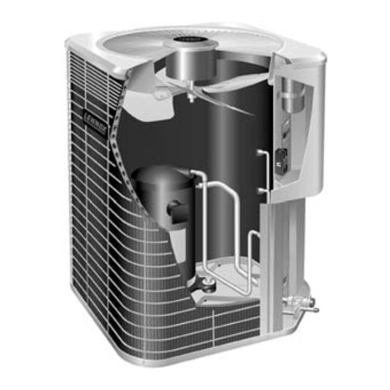
Page 3: Typical Unit Parts Arrangement
Typical Unit Parts Arrangement CONTROL BOX NOTE PLUMBING LAYOUT AND COMPRESSOR TYPE MAY VARY SLIGHTLY BETWEEN MODEL SIZES. COMPRESS0R SINGLE FAN RELAY (K10) (G−VOLTAGE DISCHARGE UNITS ONLY) MUFFLER CAPACITOR LINE (C12) COMPRESSOR HARNESS LOW PRESSURE GROUND SWITCH (S87) DEFROST CONTROL (A108) REVERSING VALVE (R1) -
Page 4: Operating Gauge Set And Service Valves
Each valve is equipped with a service port which has a recess. factory−installed valve stem. Figure 2 provides information See the Lennox Service and Application Notes #C−08−1 on how to access and operating both angle and ball service for further details and information. - Page 5 Operating Angle Type Service Valve: 1. Remove stem cap with an appropriately sized wrench. 2. Use a service wrench with a hex−head extension (3/16" for liquid line valve sizes and 5/16" for vapor line valve sizes) to back the stem out counterclockwise as far as it will go. SERVICE PORT CAP SERVICE PORT CORE (VALVE STEM SHOWN...
-
Page 6: Recovering Refrigerant From Existing System
Recovering Refrigerant from Existing System RECOVERING REFRIGERANT FROM SYSTEM DISCONNECT POWER CONNECT MANIFOLD GAUGE SET Disconnect all power to the existing outdoor unit at the service Connect a gauge set, clean recovery cylinder and a recovery disconnect switch or main fuse box/breaker panel. machine to the service ports of the existing unit. - Page 7 MINIMUM CLEARANCE CLEARANCE ON ALL SIDES INCHES (MILLIMETERS) ABOVE UNIT 6 (152) ACCESS PANEL NOTES: 48 (1219) Clearance to one of the other three sides must be 36 inches (914mm). 30 (762) 12 (305) Clearance to one of the remaining two sides may be 12 inches (305mm) and the final side may be 6 inches (152mm).
-
Page 8: New Unit Placement
Install the unit at a minimum of 4 inches (102 mm) above assistance. the surface of the roof. Ensure the weight of the unit is To obtain the correct information from Lennox, be sure to properly distributed over roof joists and rafters. Redwood communicate the following points: or steel supports are recommended. - Page 9 Models Liquid Line Vapor Line Liquid Line Vapor Line L15 Line Set TPA036H4N4 3/8 in. (10 mm) 7/8 in (22 mm) 3/8 in. (10 mm) 7/8 in (22 mm) L15−65 15 ft. − 50 ft. (4.6 m − 15 m)
-
Page 10: Brazing Connections
Polyol ester (POE) oils service valve and repeat procedure starting at are used in Lennox units charged with HFC−410A paragraph 4 for brazing the liquid line to service port refrigerant. Residual mineral oil can act as an valve. - Page 11 CAP AND CORE REMOVAL CUT AND DEBUR Cut ends of the refrigerant lines square (free from nicks or dents) Remove service cap and core from both the and debur the ends. The pipe must remain round. Do not crimp end vapor and liquid line service ports.
- Page 12 WRAP SERVICE VALVES To help protect service valve seals during brazing, wrap a saturated cloth around service valve bodies and copper tube stub. Use another saturated cloth underneath the valve body to protect the base paint. FLOW NITROGEN Flow regulated nitrogen (at 1 to 2 psig) through the refrigeration gauge set into the valve stem port connection on the liquid service valve and out of the suction / vapor valve stem port.
-
Page 13: Flushing Line Set And Indoor Coil
Flushing Line Set and Indoor Coil Flushing is only required if existing indoor coil and line set are to be used. Otherwise proceed to Installing Indoor Metering Device on page 14. TYPICAL EXISTING FIXED ORIFICE TYPICAL EXISTING EXPANSION VALVE REMOVAL PROCEDURE REMOVAL PROCEDURE (UNCASED COIL (UNCASED COIL SHOWN) SHOWN) -
Page 14: Installing Indoor Metering Device
Refer to below illustration for reference during installation of expansion valve unit. . See the Lennox TPA*H4 Engineering Handbook for approved expansion valve kit match ups. The expansion After installation of the indoor coil metering device, valve unit can be installed internal or external to the indoor proceed to Leak Test Line Set and Indoor Coil on page 15. -
Page 15: Leak Test Line Set And Indoor Coil
Take down to 1 or 2 psig (6.9 to 13.8 kPa). care to empty all existing traps. Polyol ester (POE) oils are used in Lennox units charged with HFC−410A WARNING refrigerant. Residual mineral oil can act as an insulator, preventing proper heat transfer. -
Page 16: Evacuating Line Set And Indoor Coil
Evacuating Line Set and Indoor Coil CONNECT GAUGE SET HIGH NOTE Remove cores from service valves (if not already done). Connect low side of manifold gauge set with 1/4 SAE in−line tee to vapor line service valve Connect high side of manifold gauge set to liquid line service valve OUTDOOR MANIFOLD... -
Page 17: Electrical
defined as any gas that will not condense under WARNING temperatures and pressures present during operation of an air conditioning system. Non−condensables and water Danger of Equipment Damage. Avoid deep vacuum suction combine with refrigerant to produce substances operation. Do not use compressors to evacuate a that corrode copper piping and compressor parts. - Page 18 CONTROL READ WARNING AND NOTE COMPRESSOR CONTACTOR CAPACITOR WARNING! − ELECTRIC SHOCK HAZARD. Can cause OUTDOOR INJURY or DEATH. Unit must be grounded in FAN RELAY accordance with national and local codes. (460VAC ONLY) NOTE − For use with copper conductors only. Refer to unit rating plate for minimum circuit ampacity and maximum over-current protection size.
- Page 19 Figure 14. Typical 460 VAC Unit Wiring Diagram WIRING CONNECTIONS 1. Install line voltage power supply to unit from a properly sized disconnect switch. Any excess high voltage field wiring should be trimmed or secured away from the low voltage field wiring. OUTDOOR UNIT THERMOSTAT INDOOR UNIT...
- Page 20 Figure 17. Typical Factory Wiring Diagram Y Voltage (208/230V, 3−PH) Page 20 506650−01...
- Page 21 Figure 18. Typical Factory Wiring Diagram G Voltage (460V, 3−PH) Page 21 TPA*H4 SERIES...
-
Page 22: Servicing Unit Delivered Void Of Charge
Table 3. Wire Run Lengths 1. Leak check system using procedure outlined in this instruction. Wire run length AWG # Insulation type 2. Evacuate the system using procedure outlined in this Less than 100 feet (30 m) Color−coded with a minimum instruction. - Page 23 GAUGE SET MANIFOLD GAUGE SET CONNECTIONS FOR TESTING AND CHARGING HIGH TRUE SUCTION PORT CONNECTION OUTDOOR UNIT REFRIGERANT TANK CHARGE IN LIQUID PHASE DIGITAL SCALE TEMPERATURE SENSOR (LIQUID LINE) LIQUID LINE TO LIQUID SERVICE LINE SERVICE PORT VALVE TEMPERATURE SENSOR AClose manifold gauge set valves and connect the center hose to a cylinder of HFC−410A.
- Page 24 WEIGH IN SUBCOOLING method for adding initial refrigerant charge, and then use method for verifying refrigerant charge. CALCULATING SYSTEM CHARGE FOR WEIGH IN OUTDOOR UNIT VOID OF CHARGE If the system is void of refrigerant, first, locate and repair any leaks and then weigh in the refrigerant charge into the unit.
- Page 25 Table 5. Indoor Unit Match ups and Target Subcooling Values Target Target Target *Add *Add *Add Subcooling Subcooling Subcooling INDOOR MATCHUPS INDOOR MATCHUPS INDOOR MATCHUPS charge charge charge Heating Cooling Heating Cooling Heating Cooling (+5ºF) (+1ºF) (+5ºF) (+1ºF) (+5ºF) (+1ºF) TPA*H4−036 14HPX/XP14/TPA*H4−042 (Continued) 14HPX/XP14/TPA*H4−048 (Continued)
-
Page 26: System Operation
Table 7. HFC−410A Temp. (°F) − Pressure (Psig) UNIT COMPONENTS High Pressure Switch (S4) °F Psig °F Psig °F Psig °F Psig When the high pressure switch trips, the demand defrost −40 10.1 80.5 158.2 278.2 control will cycle off the compressor, and the strike counter −35 13.5 82.3... - Page 27 compressor demand, it reverts to a lockout mode and Internal Solenoid (L34) displays the appropriate code. The demand defrost The internal unloader solenoid controls the two−stage control detects open sensor or out-of-temperature operation of the compressor by shifting a slide ring sensor range.
- Page 28 Demand Defrost Control (A108) The demand defrost control measures differential temperatures to detect when the system is performing poorly because of ice build−up on the outdoor coil. The controller self−calibrates when the defrost system starts and after each system defrost cycle.
- Page 29 HS−PS HS−PS High−Pressure Switch defrost control will count one strike. Line output 24VAC service light output. 24VAC typically used to supply power to the Lennox System 24 Volt output Operation Monitor (LSOM) Page 29 TPA*H4 SERIES...
- Page 30 DEMAND DEFROST CONTROL (A108) DIAGNOSTIC LEDS The state (Off, On, Flashing) of two LEDs on the demand defrost control (DS1 [Red] and DS2 [Green]) indicate diagnostics conditions that are described as follows. Table 9. Demand Defrost Control (A108) Diagnostic LEDs Green Condition/Code Possible Cause(s)
-
Page 31: Defrost System
Pressure Switch 5−Strike Lockout Defrost System The internal control logic of the demand defrost control counts the pressure switch trips only while the Y1 (Input) EMERGENCY HEAT (AMBER LIGHT) line is active. If a pressure switch opens and closes four An emergency heat function is designed into some room times during a Y1 (Input), the control logic will reset the thermostats. - Page 32 Defrost Temperature Termination Shunt (Jumper) Note: The Y1 input must be active (ON) and the O room Pins (P1) thermostat terminal into demand defrost control must be The demand defrost control selections are: 50, 70, 90, and inactive. 100°F (10, 21, 32 and 38°C). The shunt termination pin is DETAILED DEFROST SYSTEM OPERATION factory set at 50°F (10°C).
- Page 33 DEFROST CONTROL (A108) CALIBRATION MODE SEQUENCE Occurs after power up and cooling operation, or if the coil temperature exceeds the termination temperature while in Heat Mode. Demand defrost control defaults to 30 minute Time / Temperature Mode Reset Compressor Runtime / Reset Three / Five Strike Counter DEMAND MODE THIRTY (30) MINUTE TIME / 45 MINUTE...
- Page 34 Table 12. Ambient (RT13) and Coil (RT21) Sensors Temperature / Resistance Range Degrees Degrees Degrees Degrees Resistance Resistance Resistance Resistance Fahrenheit Fahrenheit Fahrenheit Fahrenheit 136.3 2680 56.8 16657 21.6 44154 −11.3 123152 133.1 2859 56.0 16973 21.0 44851 −11.9 125787 130.1 3040 55.3...
- Page 35 TEST Placing the jumper on the field test pins (P1) allows the technician to: Clear short cycle lockout Clear five−strike fault lockout Cycle the unit in and out of defrost mode Place the unit in defrost mode to clear the coil When Y1 is energized and 24V power is being applied to the Control, a test cycle can be initiated by placing a jumper on the Control’s TEST pins for 2 to 5 seconds.
-
Page 36: Maintenance
No further lubrication is needed. Indoor Unit 3. Visually inspect all connecting lines, joints and coils for 1. Clean or change filters. evidence of oil leaks. 2. Lennox blower motors prelubricated 4. Check all wiring for loose connections. permanently sealed. No more lubrication is needed. - Page 37 (preferably twice a year, but at least once a Heat Pump Operation year) to inspect and service your outdoor unit. The Your new Lennox heat pump has several characteristics following maintenance may be performed by the that you should be aware of: homeowner.
- Page 38 2. The outdoor coil is protected by an inner mesh screen 9 PINS USED ON −048 and a wire cage (see figure 25). If debris has collected AND −060; 6 PINS ALL OTHERS between the mesh screen and the coil and cannot be dislodged by spraying unpressurized water from inside coil surface to the outside, the mesh may be removed by first removing the top of the unit which will...
-
Page 39: Checklist
Checklists Two−Stage Modulation Compressors Field Operational Checklist Expected results during Y2 Unit Readings Y1 − First-Stage demand (Toggle switch On) Y2 − Second-Stage COMPRESSOR Voltage Same Amperage Higher OUTDOOR UNIT FAN MOTOR Amperage Same or Higher TEMPERATURE Ambient Same Outdoor Coil Discharge Air Higher Compressor Discharge Line Higher... - Page 40 TPA*H4 Checklist Job Name Job no. Date Job Location City State Installer City State Unit Model No. Serial No. Service Technician Nameplate Voltage Rated Load Ampacity Compressor Outdoor Fan Maximum Fuse or Circuit Breaker Electrical Connections Tight? - Indoor Filter clean? - Supply Voltage (Unit Off) Indoor Blower RPM S.P.
Need help?
Do you have a question about the TPA036H4N4 and is the answer not in the manual?
Questions and answers