Sharp MX-M200D Service Manual
Hide thumbs
Also See for MX-M200D:
- Operation manual (108 pages) ,
- Software setup manual (40 pages) ,
- Configuration manual (2 pages)
Table of Contents
Advertisement
Quick Links
MX-M160D
MX-M160
[ 1 ] GENERAL . . . . . . . . . . . . . . . . . . . . . . . . . . . . . . . . . . . . . . . . . 1 - 1
[ 2 ] CONFIGURATION. . . . . . . . . . . . . . . . . . . . . . . . . . . . . . . . . . . 2 - 1
[ 3 ] SPECIFICATIONS. . . . . . . . . . . . . . . . . . . . . . . . . . . . . . . . . . . 3 - 1
[ 4 ] CONSUMABLE PARTS. . . . . . . . . . . . . . . . . . . . . . . . . . . . . . . 4 - 1
[ 5 ] EXTERNAL VIEWS AND INTERNAL STRUCTURES . . . . . . . 5 - 1
[ 6 ] ADJUSTMENTS . . . . . . . . . . . . . . . . . . . . . . . . . . . . . . . . . . . . 6 - 1
[ 7 ] SIMULATIONS . . . . . . . . . . . . . . . . . . . . . . . . . . . . . . . . . . . . . 7 - 1
[ 8 ] USER PROGRAMS . . . . . . . . . . . . . . . . . . . . . . . . . . . . . . . . . 8 - 1
[ 9 ] TROUBLE CODE LIST . . . . . . . . . . . . . . . . . . . . . . . . . . . . . . . 9 - 1
[10] MAINTENANCE . . . . . . . . . . . . . . . . . . . . . . . . . . . . . . . . . . . 10 - 1
[11] DISASSEMBLY AND ASSEMBLY . . . . . . . . . . . . . . . . . . . . . . 11 - 1
[12] FLASH ROM VERSION UP PROCEDURE . . . . . . . . . . . . . . 12 - 1
[13] ELECTRICAL SECTION . . . . . . . . . . . . . . . . . . . . . . . . . . . . . 13 - 1
Parts marked with "
" are important for maintaining the safety of the set.
Be sure to replace these parts with specified ones for maintaining the safety and performance of the set.
SERVICE MANUAL
MX-M200D
CONTENTS
SHARP CORPORATION
CODE : 00ZMXM200DS1E
DIGITAL
MULTIFUNCTIONAL
SYSTEM
MX-M200D
MX-M200DK
MX-M160D
MX-M160DK
MX-M160
MODEL
As for the content of the MX-M200DK/MX-M160DK, refer to the
content of the MX-M200D/MX-M160D as long as there is no
proviso.
This document has been published to be used for
after sales service only.
The contents are subject to change without notice.
Advertisement
Table of Contents

Related Manuals for Sharp MX-M200D


Summary of Contents for Sharp MX-M200D
-
Page 1: Table Of Contents
MODEL MX-M200D As for the content of the MX-M200DK/MX-M160DK, refer to the content of the MX-M200D/MX-M160D as long as there is no proviso. CONTENTS [ 1 ] GENERAL ......... 1 - 1 [ 2 ] CONFIGURATION. - Page 2 CONTENTS [1] GENERAL [12] FLASH ROM VERSION UP PROCEDURE 1. Note for servicing ......1-1 1.
-
Page 3: Luokan 1 Laserlaite
CAUTION This product is a class 1 laser product that complies with 21CFR 1040.10 and 1040.11 of the CDRH standard and IEC60825-1 Edition 1.2-2001. This means that this machine does not produce hazardous laser radiation. The use of controls, adjustments or performance of procedures other than those specified herein may result in hazardous radiation exposure. -
Page 4: Note For Servicing
[1] GENERAL •poorly ventilated 1. Note for servicing Pictogram The label ( ) in the fusing area of the machine indicates the following: : Caution, risk of danger : Caution, hot surface A. Warning for servicing •exposed to direct sunlight •The fusing area is hot. - Page 5 D. Note for handling PWB and electronic parts When handling the PWB and the electronic parts, be sure to observe the following precautions in order to prevent against damage by static electricity. 1) When in transit or storing, put the parts in an anti-static bag or an anti-static case and do not touch them with bare hands.
-
Page 6: System Configurations
(2 x 250-sheet paper (JOB SEPARATOR) (FACSIMILE feed unit) EXPANSION KIT) 2. Machine configuration MX-M200D MX-M160D MX-M160 Copy Color scanner SPLC printer PCL printer Network Duplex Sort Shifter ∗1 Paper tray 2-stage 1-stage 1-stage ∗1: Except for North America MX-M200D CONFIGURATION 2-1... -
Page 7: Option List
— AR-SM5 256MB EXPANTION MEMORY BOARD — AR-MM9 FAX EXPANTION MEMORY BOARD — AR-PF1 BARCODE FONT KIT — MX-PK10 PS3 EXPANSION KIT AR-PF2 MACRO FONT FLASH ROM KIT — O: Option installation enable X: Option installation disable MX-M200D CONFIGURATION 2-2... -
Page 8: Copy Mode
600x300dpi, AE mode, A4/Letter, single surface copy with OC, in polygon 162x229 ready state 110x220 Postcard 100x148 Return postcard 200x148 Long format No. 3 120.1x235 Monarch 98.4x190.5 Western format No. 2 114x162 Western format No. 4 105x235 MX-M200D SPECIFICATIONS 3-1... - Page 9 600 (main) x 300 (sub) dpi (TEXT mode) Department O (Total of copy, printer, and scanner: 50 Dept., Gradation Reading: 256 gradations management Fax: 50 Dept.) Writing: Binary Toner save mode Set by the user program O : Available X : Not available MX-M200D SPECIFICATIONS 3-2...
- Page 10 **/ From top right to left **/ From top right to downward ** (“*” is displayed for 2UP only. “**” is displayed except for 1UP and 2UP.) Print direction Vertical/Horizontal Print after rotating 180°C MX-M200D SPECIFICATIONS 3-3...
- Page 11 “6” - “300” Angle “-90” - “90” Edit Font name Bold text On/ Off Italic face On/ Off Text set It depends on the font name. Color “0” - “255” density Print the first page On/ Off only MX-M200D SPECIFICATIONS 3-4...
-
Page 12: 4 ] Consumable Parts
MX-M160/MX-M160D/MX-M200D Name Product name Content Life Remark Toner cartridge MX-206AT Toner cartridge Life setting by A4 6% document (Toner:Net 547g With IC) Developer AR-205CD Developer 500K (Net 300g) (50x10) Drum KIT AR-205DR Drum Drum fixing plate MX-M200D CONSUMABLE PARTS 4-1... -
Page 13: Environmental Conditions
Number or X, Y, Z Indicates the month of packing. X stands for October, Y November, and Z December. Number Indicates the day of the month of packing. Alphabet Indicates the production factory. "A" for Nara Plant, “C“ for SOCC MX-M200D CONSUMABLE PARTS 4-2... -
Page 14: 5 ] External Views And Internal Structures
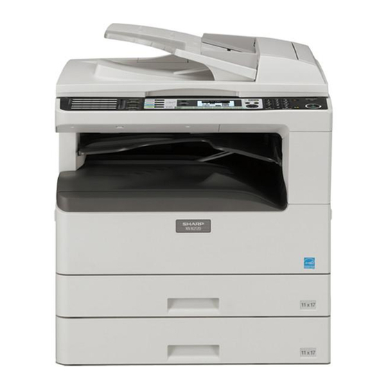
Pull out when feeding large paper such as 11" x 17" and 8-1/2" x 14" Received faxes (when the fax option is installed) and print jobs are (A3 and B4). delivered to this tray. Operation panel Contains operation keys and indicator lights. MX-M200D EXTERNAL VIEWS AND INTERNAL STRUCTURES 5-1... -
Page 15: Internal
Doing so may damage the drum and cause smudges on cop- ies. 22 Feeding roller cover 28 Fusing unit paper guide Open to remove misfed originals. Open to remove misfed paper. 23 Right side cover Open to remove misfed originals. MX-M200D EXTERNAL VIEWS AND INTERNAL STRUCTURES 5-2... -
Page 16: Operation Section
26 [START] key ( ) / indicator Press to clear the set number of copies or stop a copy run. Copying is possible when this indicator is on. Press the key to start copying. MX-M200D EXTERNAL VIEWS AND INTERNAL STRUCTURES 5-3... -
Page 17: Motor, Solenoid, Clutch
Mirror motor Drives the optical mirror base (scanner unit). Toner motor Toner supply Duplex motor Switchback operation and paper exit motor in duplex. (Only for MX-M160D/MX-M200D) Cooling fan motor Cools the inside of the machine. Main motor Drives the machine. -
Page 18: Sensor, Switch
/ JOBS_DLD Job separator tray lower limit position detection OC sensor OCSW Original cover and SPF open/close detection Original size sensor(Main Scaning) DSIN0 Original size detection Original size sensor(Sub Scaning) DSIN1 Original size detection MX-M200D EXTERNAL VIEWS AND INTERNAL STRUCTURES 5-5... -
Page 19: Pwb Unit
High voltage control Power PWB AC power input/DC power control Operation main PWB Operation panel input/Display, operation panel section control LCD OPE PWB Display and operation panel control IMC2 PWB Electronic sort, USB2.0 MX-M200D EXTERNAL VIEWS AND INTERNAL STRUCTURES 5-6... -
Page 20: Cross Sectional View
2nd tray paper transport roller Transports paper from the 2nd tray. (MX-M200D only) 2nd tray paper pick up roller Picks up paper from the 2nd tray. (MX-M200D only) 1st tray paper feed roller Picks up paper from the 1st tray. -
Page 21: Adjustment Item List
When inserting a thickness gauge, be careful not to scratch the developing doctor and the MG roller. <Adjustment specification> Developing doctor gap Both ends (20mm from the both ends) : 1.5 0.1mm C (Center) (150mm from the both ends) : 1.5 0.1mm MX-M200D ADJUSTMENT 6-1... - Page 22 Example: 4/0.1 = 40 = about 40 Note:If the set value is not obtained from the above formula, perform the <Specification> fine adjustment. Mode Specification Grid bias LOW DC - 380±8V Grid bias HIGH DC - 525±10V MX-M200D ADJUSTMENT 6-2...
- Page 23 1st print surface lead edge position adjustment in advance, and Image loss: be sure to perform the 2nd print surface lead edge position 3mm or adjustment and then the lead edge void adjustment in this less sequence. MX-M200D ADJUSTMENT 6-3...
- Page 24 3) Execute SIM 50-10. After completion of warm-up, shading is performed and the currently set off center adjustment value of each paper feed port is displayed. 4) Enter the set value and press the [START] key. The correction value is stored and a copy is made. MX-M200D ADJUSTMENT 6-4...
- Page 25 6) Put No. 2/3 mirror base unit on the positioning plate again, push the with the positioning plate, perform the adjustment of 4). projections on the front frame side and the rear frame side of the copy lamp unit to the corner frame, and tighten the wire fixing screw. MX-M200D ADJUSTMENT 6-5...
-
Page 26: Rear Side
Lb: Rear edge black background width If the width (La) of the black background at the lead edge is equal that (Lb) at the rear edge, there is no need to execute the following procedures of 4) ~ 7). MX-M200D ADJUSTMENT 6-6... - Page 27 The set value is stored and a copy is made. Note:Do not adjust the rail on the rear side. If the rail on the rear side is adjusted, an error may occur. Only the rail on the front side can be adjusted. MX-M200D ADJUSTMENT 6-7...
- Page 28 <Adjustment specification> Mode Specification Set value Set range Original off Single: SIM 50-12 Add 1: 1 ~ 99 center mode Center ±2.0mm (AUTO 0.1mm shift (OC mode) indicator to R side Reduce 1: 0.1mm shift to L side MX-M200D ADJUSTMENT 6-8...
- Page 29 3) Slide the lens unit toward the rear side and attach it,then execute SIM. When the lens unit is moved,execute the OC main scanning magnification ratio auto adjustment,SIM 48-1-1,SIM48-3 and the PF original off-center adjustment. This adjustment is basically O.K.with SIM 63-7. MX-M200D ADJUSTMENT 6-9...
-
Page 30: 7 ] Simulations
Duplex print counter clear *6 Paper feed counter clear Drum counter clear Copy counter clear Printer counter clear Scanner counter clear SPF/RSPF jam total counter clear *2 Scanner mode counter clear Main motor operation check (Cooling fan motor rotation check) MX-M200D SIMULATIONS 7-1... - Page 31 Copy exposure level adjustment, individual setting (Photo) 600dpi Image contrast adjustment (300dpi) Exposure mode setting (Gamma table setting/AE operation mode setting/ Photo image process setting) SPF/RSPF exposure correction *2 Image contrast adjustment (600dpi) AE limit setting Image sharpness adjustment MX-M200D SIMULATIONS 7-2...
-
Page 32: Contents Of Simulations
Used to monitor the mirror home position sensor and display the ON/OF status of the sensor on the LCD. Sim1-2 SENSOR CHECK MHPS MHPS(MIRROR HOME POSITION SENSOR) :Highlight display :Normal display [CA] key: Exits the simulation mode. [INTERRUPT] key: Returns to the sub code input window. MX-M200D SIMULATIONS 7-3... - Page 33 "EXEC" is highlighted during execution. 100% ZOOM 100% EXEC [CA] key: The SPF/RSPF motor is stopped, and the machine exits the simulation mode. [INTERRUPT] key: The SPF/RSPF motor is stopped, and the machine returns to the sub code input window. MX-M200D SIMULATIONS 7-4...
- Page 34 JSUP JSDL JSUP :Job separator upper limit sensor TRYF TRYD JSDL :Job separator lower limit sensor TRYF :Tray full sensor TRYD : Paper exit sensor * Displayed only when the job separator is installed except for SFTH. MX-M200D SIMULATIONS 7-5...
- Page 35 [ ] key: Shift to the home position. [SFTHP] is highlighted when the HP sensor is detected. (Initial window) Sim3-11 SHIFTER CHK SFTHP ]:R [ ]:HP [ [CA] key: Exits the simulation mode. [INTERRUPT] key: Returns to the sub code input window. MX-M200D SIMULATIONS 7-6...
- Page 36 * Note for the key input check mode [START] key must be pressed at the end. If it is pressed midway, the simulation judges that the last key is pressed and terminates the check mode. Multi input of tow or more keys is ignored. MX-M200D SIMULATIONS 7-7...
- Page 37 When the operation is completed, the machine returns to the sub code input window. When [INTERRUPT] key is pressed, the machine returns to the sub code input window. When [CA] key is pressed, the machine exits the simulation mode. MX-M200D SIMULATIONS 7-8...
- Page 38 (Execution start window) (Copy window) Ready to copy. Sim7-6 INTERVAL SET AGING INTERVAL 100% AER YOU SURE? EXEC 8 1/2 11 It is canceled by turning off the power or executing a simulation with the hard reset. MX-M200D SIMULATIONS 7-9...
- Page 39 (Execution start window) (Execution window) Sim8-3 MHV(L) Sim8-3 MHV(L) [OK] key or [START] Key PRESS OK KEY EXEC EXEC [CA] key: Exits the simulation mode. [INTERRUPT] key: Interrupts output operation and shifts to the sub code input window. MX-M200D SIMULATIONS 7-10...
- Page 40 (Execution window) Sim9-2 DMR CHECK Sim9-2 DMR CHECK [OK] key or [START] Key PRESS OK KEY EXEC EXEC [CA] key: Exits the simulation mode. [INTERRUPT] key: Interrupts the output operation, and shifts to the sub code input window. MX-M200D SIMULATIONS 7-11...
- Page 41 When this simulation is executed, the following execution start window is displayed. Press [OK] key or [START] key to clear the trouble other than U2. (Execution start window) Sim14 TROUBLE CLEAR TROUBLE CLEAR (WITHOUT U2) AER YOU SURE? EXEC MX-M200D SIMULATIONS 7-12...
- Page 42 DRM TTL : nnnnnnn MMTCYC : nnnnnnn Though SIM26-74 is set to “1: Scan counter is added,” the count is not added to SIM22-01 total counter display. The setting affects only the total counter display in the system settings. MX-M200D SIMULATIONS 7-13...
- Page 43 [INTERRUPT] key: Shifts to the sub code input window. key, key: Switches to another page. Sim22-9 COUNTER 1/2 Sim22-9 COUNTER 2/2 BYPASS : nnnnnnn TRAY4 : nnnnnnn TRAY1 : nnnnnnn TRAY2 : nnnnnnn TRAY3 : nnnnnnn * TRAY2-TRAY4 are displayed only when they are installed. MX-M200D SIMULATIONS 7-14...
- Page 44 When [OK] key or [START] key is pressed, the jam total count and the jam memory are cleared and the machine shifts to the sub code input window. Sim24-1 COUNTER CLR JAM COUNTER CLEAR AER YOU SURE? EXEC MX-M200D SIMULATIONS 7-15...
- Page 45 Drum counter clear Used to clear the drum counter and the drum rotating time. Sim24-7 COUNTER CLR DRUM COUNTER CLEAR AER YOU SURE? EXEC [CA] key: Exits the simulation mode. [INTERRUPT] key: Shifts to the sub code input window. MX-M200D SIMULATIONS 7-16...
- Page 46 AER YOU SURE? EXEC [OK] key or [START] key: Clears the scanner mode counter and shifts to the sub code input window. [CA] key: Exits the simulation mode. [INTERRUPT] key: Shifts to the sub code input window. MX-M200D SIMULATIONS 7-17...
- Page 47 It takes about 3 minutes to complete the SIM25-02. Never open the front cover or turn OFF the machine power during execution of this simulation. MX-M200D SIMULATIONS 7-18...
- Page 48 2. For Japan, the duplex copy use inhibition setting is ON (inhibited). 3. When the auditor mode exclusive-setting is ON (manual paper feed inhibited) and the standard tray is set to the manual feed tray, the standard tray setting is set to the main tray. MX-M200D SIMULATIONS 7-19...
- Page 49 O SIM46-30 (AE limit setting) O Paper size (A4 for AB series, LT for inch series) O Maintenance cycle (Returns to the default (Japan/Ex Japan). ) O Mini maintenance cycle (Only when setting is changed to Japan.) MX-M200D SIMULATIONS 7-20...
- Page 50 Sim26-22 LANGUAGE Sim26-22 LANGUAGE LANGUAGE SETTING LANGUAGE SETTING [OK] key or [START] Key CLEAR CLEAR AER YOU SURE? EXEC EXEC Sim26-22 LANGUAGE PLEASE SHUT OFF THE POWER. After completion of counter clear and shifting to the lock position. MX-M200D SIMULATIONS 7-21...
- Page 51 "Stop" or "Cancel of stop" can be selected when the drum counter reaches the life over. Code: Setting Sim26-37 DEVE STOP 0 : Stop 1:DRM LIFE OVER 1 : Cancel of stop [ 0-1 ] [CA] key: Exits the simulation mode. [INTERRUPT] key: Shifts to the sub code entry menu. MX-M200D SIMULATIONS 7-22...
- Page 52 * The default (38) of transfer ON timing means 320ms from PS release. The default (50) of the transfer OFF timing means304ms from P-IN OFF. [CA] key: Exits the simulation mode. [INTERRUPT] key: Shifts to the sub code input window. MX-M200D SIMULATIONS 7-23...
- Page 53 * When [OK] key or [START] key is pressed, the set value of LCD contrast is immediately reflected. Sim26-54 LCD DUTY 1:LCD PWM DUTY [ 30- 70] [CA] key: Exits the simulation mode. [INTERRUPT] key: Shifts to the sub code input window. MX-M200D SIMULATIONS 7-24...
- Page 54 Used to set whether the scanner counter value is added to the total counter display in the system settings. Sim26-74 ADD COUNT 0 : Scan counter not added 1 : Scan counter added 1:ADD SCAN CNT 0- 1] [CA] key: Exits the simulation mode. [INTERRUPT] key: Shifts to the sub code input window. MX-M200D SIMULATIONS 7-25...
- Page 55 The values are displayed in the range of 0 - 255. 0 (Black) - 255 (White) The value in [ ] indicates the adjustment threshold value. "EXEC" is highlighted during execution. OCSW Original cover status Open: Highlighted Close: Normal display 1 - 5 PD sensor detection level MX-M200D SIMULATIONS 7-26...
- Page 56 4 : 180 C [160- 200] 5 : 185 C 6 : 190 C 7 : 195 C 8 : 200 C [CA] key: Exits the simulation mode. [INTERRUPT] key: Shifts to the sub code input window. MX-M200D SIMULATIONS 7-27...
- Page 57 Unconditional toner supply When the developing unit and the drum unit are rotating, a small quantity of toner is consumed. For assuring this operation, toner is supplied according to the rotation time of the developing unit. MX-M200D SIMULATIONS 7-28...
- Page 58 1:AE : AE MODE (300dpi) 2:TEXT : TEXT MODE (300dpi) 3:PHOTO 1 : PHOTO MODE (Error diffusion) 4:PHOTO 2 : PHOTO MODE (Dither) 5:TEXT (TS) : TS MODE (TEXT) (300dpi) 6:AE (TS) : TS MODE (AE) (300dpi) MX-M200D SIMULATIONS 7-29...
- Page 59 1- 99] 1- 99] 1- 99] Sim46-9 TEXT 300 Sim46-9 TEXT 300 Sim46-9 TEXT 300 13:TS 2.0(SHIFT) 16:TS 3.0(GAMMA) 19:TS 5.0(SHIFT) 20:TS 5.0(GAMMA) 14:TS 2.0(GAMMA) 17:TS 4.0(SHIFT) 15:TS 3.0(SHIFT) 18:TS 4.0(GAMMA) 1- 99] 1- 99] 1- 99] MX-M200D SIMULATIONS 7-30...
- Page 60 1- 99] 1- 99] 1- 99] Sim46-10 TEXT 600 Sim46-10 TEXT 600 Sim46-10 TEXT 600 13:TS 2.0(SHIFT) 16:TS 3.0(GAMMA) 19:TS 5.0(SHIFT) 14:TS 2.0(GAMMA) 17:TS 4.0(SHIFT) 20:TS 5.0(GAMMA) 15:TS 3.0(SHIFT) 18:TS 4.0(GAMMA) 1- 99] 1- 99] 1- 99] MX-M200D SIMULATIONS 7-31...
- Page 61 The adjustment range is 1 - 99. When [ ] key or [ ] key is pressed, the page is changed. The shift amount and the slanting value can be individually set for each of five levels of density for each of PHOTO mode (error diffusion and dither). Therefore, there are 20 patterns of adjustment modes. MX-M200D SIMULATIONS 7-32...
- Page 62 3:PHOTO 1 1- 99] 1- 99] Enter an adjustment value and press [OK] key. The entered value is saved to the EEPROM and the machine shifts to the copy window. Sample copying can be performed during this simulation. MX-M200D SIMULATIONS 7-33...
- Page 63 Sim46-20 SPF EXP. 1:SPF EXPOSURE [ 1- 99] The adjustment value is in the range of 1 - 99. Adjustment value (Image change) 99 (Dark) • • • 50 (Default) • • • 1 (Light) MX-M200D SIMULATIONS 7-34...
- Page 64 EEPROM. The adjustment value is in the range of 0 - 31. * Note: When SIM26 - 06 (Destination setting) and SIM46 - 19 (Auto exposure mode) are changed, this setting returns to the default accordingly. MX-M200D SIMULATIONS 7-35...
- Page 65 Ready to copy. Adjustment Copy start [OK] key item selection 100% window window 8 1/2 11 [START] key (Copy execution window) Copies in progress. Copy execution [START] key window 100% 8 1/2 11 End of copy execution MX-M200D SIMULATIONS 7-36...
- Page 66 8 1/2 11 End of copy execution * The exposure mode is fixed to "TEXT" with density 3, and cannot be changed. * For the model without RSPF, the adjustment item of document back is not displayed. MX-M200D SIMULATIONS 7-37...
- Page 67 Sum check error (Overrun, Fleming, parity) (Print window data) 0x18 MCU receive time-out Sum check error (Fax window data) 0x19 FAX communication error Panel-MCU communication error 0x1A PANEL communication error 0x1B Download file error Download file error MX-M200D SIMULATIONS 7-38...
- Page 68 0.1mm, increasing the image loss amount. Note 5: When the print start position (TRAY1) is changed, the print start positions (TRAY2 - TRAY4) and the print start position (MULTI BYPASS) are also changed accordingly. MX-M200D SIMULATIONS 7-39...
- Page 69 When the value of [4:DEN - A] is increased by 10, the void amount is increased by about 1mm. (For 25 or less, the void amount is zero.) [Example] Copy output result Paper lead edge Distance between the Scale image loss paper lead edge to the amount image lead edge R=4.0mm H=5.0mm MX-M200D SIMULATIONS 7-40...
- Page 70 When the adjustment value is increased, the output image is shifted to the right. When the adjustment value is increased by 1, the image is shifted to the right by about 0.1mm. Select an adjustment item (mode) with the arrow keys, and enter the set value with numeric keys. MX-M200D SIMULATIONS 7-41...
- Page 71 Ready to copy. Adjustment Copy start [OK] key item selection 100% window window 8 1/2 11 [START] key (Copy execution window) Copies in progress. Copy execution [START] key window 100% 8 1/2 11 End of copy execution MX-M200D SIMULATIONS 7-42...
- Page 72 Ready to copy. Adjustment Copy start [OK] key item selection 100% window window 8 1/2 11 [START] key (Copy execution window) Copies in progress. Copy execution [START] key window 100% 8 1/2 11 End of copy execution MX-M200D SIMULATIONS 7-43...
- Page 73 :resist amount on RSPF document back (*1) 8:RSPF A5 :Document resist amount in A5 document back transport (*1) 9:DUPLEX :Resist amount in DUPLEX print (Second print surface) (*1) 10: PRE FEED :Pre-feed time of the manual feed tray paper feed. (*2) MX-M200D SIMULATIONS 7-44...
- Page 74 Sim53-8 SPF AUTO Sub code input standby window EXEC adjustment [OK] key or [START] Key Sim53-8 SPF AUTO When the automatic adjustment result is NG, "ERR" is displayed on the value display. PRESS OK KEY EXEC MX-M200D SIMULATIONS 7-45...
- Page 75 * The white level is displayed for about 10sec. The data update cycle is about 1sec. 5. After passing 10sec, the machine returns to the sub code input window. Sim63-1 SHADING Sim63-1 SHADING [OK] key or [START] key PRESS OK KEY EXEC MX-M200D SIMULATIONS 7-46...
- Page 76 (Images are not formed on the drum.) (Initial window) Ready to copy. Copies in progress. [OK] Key or [START] Key 100% 100% 8 1/2 11 8 1/2 11 After completion of printing one sheet 7SEG LED MX-M200D SIMULATIONS 7-47...
- Page 77 : NORMAL 2 Slow : SAFE 1- 4] * When images are disturbed in printing through USB, change the setting and try again. [CA] key: Exits from the simulation mode. [INTERRUPT] key: Shifts to the sub code entry window. MX-M200D SIMULATIONS 7-48...
-
Page 78: User Programs
SORT AUTO SELECT No sort, Sort* RESOLUTION IN AUTO/TEXT MODE 300*, 600dpi PHOTO MODE DEFAULT Pattern 1*, 2 LIMIT OF COPIES 99, 999*copies DISABLE AUTO PAPER SELECTION Check box unchecked DISABLE 2-SIDED COPY Check box unchecked MX-M200D SYSTEM SETTINGS 8-1... -
Page 79: Using The System Settings
• “ ” appears for each digit that you enter. • The mode selection screen appears. 5) Select the desired mode with the [ ] or [ ] key. MODE SELECT CHANGE ADMIN PW COPIER PRINTER SCANNER Example: The screen when “COPIER” is selected. MX-M200D SYSTEM SETTINGS 8-2... -
Page 80: Trouble Code List
Panel board communication trouble (Overrun) remedy Check the ROM of the IMC PWB. Panel board communication trouble (Framing) Panel board communication trouble (Time out) Panel language error Auditor NOT READY None Door open None Developing cartridge installed Blink MX-M200D TROUBLE CODE LIST 9-1... - Page 81 The CCD black scan level is abnormal when the shading. Cause Improper connection of the CCD unit flat cable CCD unit abnormality. MCU PWB abnormality. Check Check connection of the CCD unit flat cable. Check the CCD unit. remedy MX-M200D TROUBLE CODE LIST 9-2...
- Page 82 MX-NB10 board communication trouble. Check Replace the FAX board. Detail MX-NB10 print data reception error. Cause Print data cannot be received from the MX- remedy NB10 for 3 min or more. Check Reset the machine (Power OFF/ON). remedy MX-M200D TROUBLE CODE LIST 9-3...
- Page 83 Check the POUT sensor harness. Check remedy Check connection of the harness/connector of remedy installation of the fusing unit. the shifter motor. Use SIM14 to clear the self diag display. Replace the shifter motor. Replace the MCU PWB. MX-M200D TROUBLE CODE LIST 9-4...
- Page 84 Replace the panel or the MCU PWB. Check Replace the chip. Reset the machine. (Power OFF/ON). Check installation of the developing unit. remedy remedy Use SIM 16 to cancel the trouble. Replace the MCU PWB. MX-M200D TROUBLE CODE LIST 9-5...
-
Page 85: Maintenance
Transport (paper exit) rollers Spring clutch Fusing section Upper heat roller Pressure roller Pressure roller bearing Upper separation pawl Lower separation pawl Cleaning pad Drive section Gears Belts Paper exit VOC filter section *1:Recommendable replacement time:50K(A4/Letter,6%print) MX-M200D MAINTENANCE 10-1... -
Page 86: Maintenance Display System
When a waste toner cartridge is removed from the machine, it must be put in a polyethylene bag to avoid scattering of toner. B. DV cartridge Do not shake or put up the developer cartridge. Otherwise developer may scatter. MX-M200D MAINTENANCE 10-2... -
Page 87: Disassembly And Assembly
Tray paper feed section/Paper transport section Bypass tray section Power section Developing section Process section Others 1. High voltage section/Duplex transport section Content Transfer charger unit Charger wire Duplex transport section A.Transfer charger unit C.Duplex transport section MX-M200D DISASSEMBLY AND ASSEMBLY 11-1... -
Page 88: Optical Section
Be sure to put No. 2/3 mirror unit to the positioning plate (A). Assembly: Put the notched surface of wire holder (3) downward, tighten temporarily, and install. Adjustment: Main scanning direction distortion balance adjustment D.Copy lamp MX-M200D DISASSEMBLY AND ASSEMBLY 11-2... - Page 89 •When the copy image is shorter than the original, shift to the negative (-) direction. 1 scale of the scribed line corresponds to 0.34% of magnification ratio. If this adjustment is not satisfactory, make a fine adjustment with SIM 48-2. MX-M200D DISASSEMBLY AND ASSEMBLY 11-3...
-
Page 90: Fusing Section
Installation: Install in direction that the sponge side (A) of the thermistor A.Fusing unit removal comes in contact with heat roller. Check that the thermistor is in contact with the upper heat roller. M4×8 M3×12 M3×8 MX-M200D DISASSEMBLY AND ASSEMBLY 11-4... - Page 91 Floil(GU2) Grease(JFE552) Assembly: Put the fusing harness (A) on the heater lamp (B) as shown in the figure and fix them together. Place the fusing harness inside the rib (C). MX-M200D DISASSEMBLY AND ASSEMBLY 11-5...
-
Page 92: Paper Exit Section
(C) of the rib on a line, and tighten the screw firmly. Except for Taiwan: A.Ozone filter Lower the fusing front paper guide to the bottom of the adjustment width, and tighten the screw firmly. Grease (JFE552) For Taiwan Except for Taiwan MX-M200D DISASSEMBLY AND ASSEMBLY 11-6... - Page 93 B.Cooling fan MX-M160D/M200D MX-M160 C.Paper exit unit D.Paper exit sensor / duplex sensor (A)Exit sensor (B)Duplex sensor *(2) MX-M200D DISASSEMBLY AND ASSEMBLY 11-7...
- Page 94 (B). A.MCU disassembly Be sure to insert two ribs (C) into the groove (D). Note:When replacing the MCU PWB, be sure to replace the EEPROM of the MCU PWB to be replaced. MX-M200D DISASSEMBLY AND ASSEMBLY 11-8...
-
Page 95: Optical Frame Unit
Content Content Middle frame unit LSU unit Drive unit Solenoid (paper feed solenoid,, resist roller solenoid) A. LSU unit Resist roller clutch / Resist roller Paper feed clutch/Paper feed roller A. Middle frame unit *(2) MX-M200D DISASSEMBLY AND ASSEMBLY 11-9... - Page 96 B. Drive unit Assembly: Move down the clutch pawl as shown below, and avoid the clutch and install. E. Paper feed clutch/Paper feed roller Moricote X56020 Apply grease (FG-40H) to the gray area (UKOG-0004QSZZ). Grease G-484 MX-M200D DISASSEMBLY AND ASSEMBLY 11-10...
-
Page 97: Bypass Tray Section
C. Bypass tray solenoid When installing the solenoid, shift it in the arrow direction and install. Installation: Be careful of the installing direction of the bypass tray transport roller (6) MX-M200D DISASSEMBLY AND ASSEMBLY 11-11... - Page 98 Note: Push the lever at the right edge of the multi frame cover to the right upper side and remove it. Apply grease (FG-40H) to the gray area (UKOG-0004QSZZ). Apply grease (FG-40H) (UKOG-0004QSZZ). E.Pressure plate unit Apply grease (FG-40H) to the gray area (UKOG-0004QSZZ). MX-M200D DISASSEMBLY AND ASSEMBLY 11-12...
-
Page 99: Power Section
10.Power section C. High voltage P.W.B. Content Power unit Power fan High voltage P.W.B. Power P.W.B. Power switch A.Power unit D. Power P.W.B. B. Power fan E. Power switch MX-M200D DISASSEMBLY AND ASSEMBLY 11-13... -
Page 100: Developing Section
Note:Attach it to fit with the attachment reference when replacing the DV blade. Attaching reference Mark-off line DV blade The DV blade surface must be free from foreign materials. Do not touch the DV blade tip. Mark-off line It must be free from deflection. reference MX-M200D DISASSEMBLY AND ASSEMBLY 11-14... -
Page 101: Process Section
When the drum is replaced, be sure to replace the drum positioning boss with a new one, too. B. Main charger unit C.Cleaning blade When installing a resistor, check to confirm that the terminal section is in contact with the metal section of the cleaning blade. MX-M200D DISASSEMBLY AND ASSEMBLY 11-15... - Page 102 B. Tray interface P.W.B. positioning pin C. 2nd tray paper entry sensor / Paper empty sensor hole [Note for installation] When installing, engage the hole of the LCD box unit with the positioning pin. MX-M200D DISASSEMBLY AND ASSEMBLY 11-16...
- Page 103 G. 2nd tray paper feed clutch E.2nd tray transport clutch Apply grease (FG-40H) to the gray area (UKOG-0004QSZZ). H. 2nd tray paper feed roller Apply grease (FG-40H) to the gray area (UKOG-0004QSZZ). F. 2nd tray transport roller MX-M200D DISASSEMBLY AND ASSEMBLY 11-17...
- Page 104 L. Paper feed roller J. Paper entry sensor When removing the paper feed roller, operate the paper feed clutch with SIM 6-1, and keep the paper feed roller down as shown in the figure above for operation. MX-M200D DISASSEMBLY AND ASSEMBLY 11-18...
-
Page 105: Flash Rom Version Up Procedure
The extension of the firmware data file is ".dwl", for example like "ARM207_162_0206_AF_all.dwl". For the "Maintenance_toolV****.zip" and the firmware data file, contact the local distributor of SHARP to obtain the latest file. 5) Select the folder which includes the maintenance tool driver (Mainte.inf), and press the OK button. -
Page 106: Firmware Update Procedure
Double click "Special (MCU)" in the main tree item to develop the sub tree items, and double click "DWL Download" in the sub tree items. 3) PC side: Execute the “Maintenance.exe”, and select [AR-M207/M162/M165 Series] on the model selection menu. <Sample display> MX-M200D FLASH ROM VERSION UP PROCEDURE 12-2... - Page 107 •For making a second connection with another machine, select the "File" and "Reconnect" in the menu bar on the maintenance program at the time of the USB being re-connected. Repeat the previous procedures MX-M200D FLASH ROM VERSION UP PROCEDURE 12-3...
-
Page 108: Electrical Section
[13] ELECTRICAL SECTION 1.Block diagram High-speed USB2.0 MM_BI0/BI1/PH_B /SYNC MM_AI0/AI1/PH_A TM+, TM /MMRDY /MMD USB1.1 MX-M200D ELECTRICAL SECTION 13-1... -
Page 109: Actual Wiring Diagram
CASSETTE EMP (Black) HARNESS CASSETTE SW HARNESS SIDE COVER SW (White) HARNESS AUDITOR OPTION OPTION COIN VENDER DEV HARNESS 9615S-16-PP-A (J:22FMN-BTRK-A) B3B-PH B5B-PH B3B-PH CRUM-MCU (Black) (White) (White) 9604S-23F (White) HARNESS 9610S-16B (J:22FMN) 9604S-23F(White) B6B-PH-K-R (LF) (Red) MX-M200D ELECTRICAL SECTION 13-2... - Page 110 ACTUAL WIRING DIAGRAM 2/7 MX-M200D ELECTRICAL SECTION 13-3...
- Page 111 ACTUAL WIRING DIAGRAM 3/7 MX-M200D ELECTRICAL SECTION 13-4...
- Page 112 ACTUAL WIRING DIAGRAM 4/7 NW AC-L N.C. NW AC-N CN005(B2P3-VH-LF) MX-M200D ELECTRICAL SECTION 13-5...
- Page 113 ACTUAL WIRING DIAGRAM 5/7 MX-M200D ELECTRICAL SECTION 13-6...
- Page 114 ACTUAL WIRING DIAGRAM 6/7 MX-M200D ELECTRICAL SECTION 13-7...
- Page 115 ACTUAL WIRING DIAGRAM 7/7 MX-M200D ELECTRICAL SECTION 13-8...
-
Page 116: Signal Name List
(Transmission type) Sensor CPEMPTY 1st tray paper empty Detects paper empty of 1st — Paper no CN18 sensor (Transmission tray empty type) Sensor RTH_IN Fusing thermistor Thermistor signal for fusing — — CN25 Analog (Thermistor) temperature detection MX-M200D ELECTRICAL SECTION 13-9... - Page 117 Detects lock of ozone fan — Lock CN115 detection Motor /PMD Polygon motor Controls polygon motor Driving Stop CN703 (Brushless motor) (LSU) driving Motor /PMRDY Polygon motor ready Detects standby of polygon Standby Stop CN703 motor MX-M200D ELECTRICAL SECTION 13-10...
- Page 118 CN26 Constant (JOBS_MT1) driving signal (Four- dirver (TRAY PWB) voltage (JOBS_MT2) phase stepping motor) (JOBS_MT3) Motor (SJMT0) Shifter motor driving Drives shifter motor driver — — CN26 (SJMT1) signal (Four-phase (TRAY PWB) (SJMT2) stepping motor) (SJMT3) MX-M200D ELECTRICAL SECTION 13-11...
- Page 119 LEAD-FREE SOLDER The PWB’s of this model employs lead-free solder. The “LF” marks indicated on the PWB’s and the Service Manual mean “Lead-Free” solder. The alphabet following the LF mark shows the kind of lead-free solder. Example: <Solder composition code of lead-free solder> Solder composition Solder composition code Solder composition...
- Page 120 CAUTION FOR BATTERY REPLACEMENT (Danish) ADVARSEL ! Lithiumbatteri – Eksplosionsfare ved fejlagtig håndtering. Udskiftning må kun ske med batteri af samme fabrikat og type. Levér det brugte batteri tilbage til leverandoren. (English) Caution ! Danger of explosion if battery is incorrectly replaced. Replace only with the same or equivalent type recommended by the manufacturer.
- Page 121 © COPYRIGHT 2009 BY SHARP CORPORATION All rights reserved. Printed in Japan. No part of this publication may be reproduced, stored in a retrieval system, or transmitted, in any form or by any means, electronic; mechanical; photocopying; recording or otherwise without prior written permission of the publisher.
Need help?
Do you have a question about the MX-M200D and is the answer not in the manual?
Questions and answers