
Subscribe to Our Youtube Channel
Related Manuals for Columbia CDVB-50


Summary of Contents for Columbia CDVB-50
- Page 1 CDVB SERIES Gas Fired Boilers For Forced Hot Water INSTALLATION, OPERATION & MAINTENANCE MANUAL olumbia ompany Main offices and Factory: Pottstown, PA 37616101 , Rev. F [05/2012]...
-
Page 2: Table Of Contents
GAS FIRED BOILERS FOR FORCED HOT WATER Introduction ..........................3 Boiler Ratings, Capacities & Dimensions ..................4 Ventilation & Combustion Air ......................6 Connecting Supply & Return Piping ....................7 Applicable Federal Codes ......................11 Vent System Modification ......................11 Horizontal Vent Pipe Installation Instructions ..................12 Vertical Vent Pipe Installation Instructions ..................22 Connecting Gas Service .......................28 Electrical Wiring .........................29... -
Page 3: Introduction
INTRODUCTION Install boiler such that gas ignition system components WARNING are protected from water, (dripping, spraying, rain, etc.), during appliance operation and service, 1. Keep boiler area clear and free from (circulator replacement, condensate trap, control combustible materials, gasoline and other replacement, etc.). -
Page 4: Boiler Ratings, Capacities & Dimensions
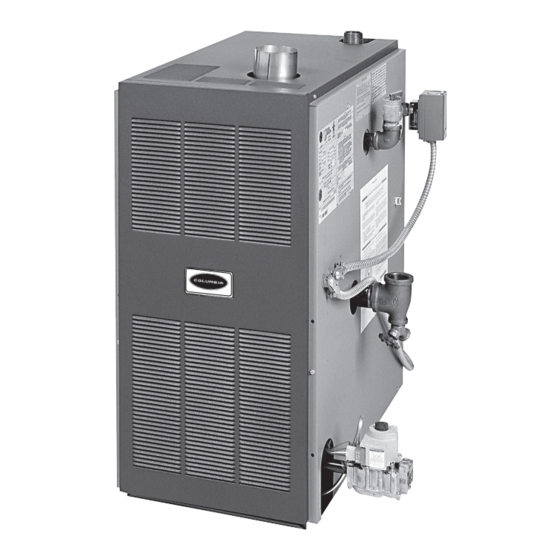
BOILER RATINGS, CAPACITIES & DIMENSIONS WARNING All installations of boilers and venting should be done only by a qualified expert and in accordance with the appropriate utica boilers manual. Installing or venting a boiler or any other gas appliance with improper methods or materials may result in serious injury or death due to fire or to asphyxiation from poisonous gases such as carbon monoxide which is odorless and invisible. - Page 5 BOILER RATINGS, CAPACITIES & DIMENSION STANDARD EQUIPMENT: Boiler Jacket, Cast Iron Boiler Battery, Combination Aquastat Relay, Theraltimeter Gauge, Circulator, Main Gas Burners, Electric Ignition System, A.S.M.E relief Valve, Drain Valve, Induced Draft Fan, and Safety Pressure Switch All boilers are design certified for installation on non-combustible floors. For installation on combustible floors, use combustible floor kit.
-
Page 6: Ventilation & Combustion Air
VENTILATION & COMBUSTION AIR Provide combustion air and ventilation air in accordance • All Outdoor Air. Provide permanent opening(s) with the section “Air for Combustion and Ventilation,” of the communicating directly or by ducts with outdoors. National Fuel Gas Code, ANSI Z223.1/NFPA 54, or Sections о... -
Page 7: Connecting Supply & Return Piping
CONNECTING SUPPLY & RETURN PIPING IMPORTANT: Circulators in following illustrations Bypass piping is option which gives ability to adjust are mounted on system supply side, but mounting on supply boiler water temperature to fit system or system return side is also acceptable practice. condition of installation. - Page 8 CONNECTING SUPPLY & RETURN PIPING Figure 2 - BYPASS PIPING SUPPLY SYSTEM TEMPERATURE GAUGE FLOW VALVE ZONE "A" CIR. VALVE "B" VALVE FEED EXPANSION WATER TANK RETURN 6" Figure 3 - MIXING VALVE PIPING SUPPLY SYSTEM TEMPERATURE GAUGE ZONE CIR. RETURN 4 WAY MIXING VALVE...
- Page 9 CONNECTING SUPPLY & RETURN PIPING Figure 4 - PRIMARY SECONDARY PIPING WITH BYPASS RETURN SYSTEM SYSTEM CIRCULATOR TEMPERATURE GAUGE 12" MAX. FLOW VALVE SUPPLY "A" PRIMARY VALVE CIRCULATOR "B" VALVE FEED WATER EXPANSION TANK 6" NOTE #1: When using bypass piping, adjust valves A and B until desired system temperature is obtained.
- Page 10 CONNECTING SUPPLY & RETURN PIPING WARNING To avoid burns, scalding, or water damage due to discharge of steam and/or hot water during operation, a discharge line shall be installed to relief valve outlet connection. Discharge line shall: • connect to relief valve outlet and piped down to safe point of disposal. Check local codes for maximum distance from floor or allowable safe point of discharge.
- Page 11 CONNECTING SUPPLY & RETURN PIPING Figure 5 - Piping with Circulator GATE VALVE SYSTEM CIRCULATOR REDUCED PRESSURE BACKFLOW PREVENTER FLOW CONTROL OR CHECK VALVE COLD WATER HOT WATER TANK INLET OUTLET CIRCULATOR PRESSURE REDUCING FEED VALVE WATER THERMAL RELIEF VALVE TRAP 6"...
-
Page 12: Applicable Federal Codes
APPLICABLE FEDERAL CODES NFPA 54/ANSI Z223.1, National Fuel Gas Code and NFPA/ When flue gas temperatures are lowered, corrosive ANSI 211, Chimneys, Fireplaces, Vents and Solid Fuel condensates may form in the gas vent or in the appliance. Burning Appliances. These codes contain information on Condensates may form in Category II, III, IV appliance special gas vents for Category II, III and IV appliances, vents, so special, corrosive resistant venting systems are... -
Page 13: Horizontal Vent Pipe Installation Instructions
HORIZONTAL VENT PIPE INSTALLATION INSTRUCTIONS Horizontal Vent Pipe Installation Instructions (Through the wall) This boiler is design certified for use with the following venting systems Company HEAT-FAB FLEX-L Z-FLEX ProTech ® ® ® ® Product SAF-T-VENT™ STAR-34™ Z-VENT™ FasNSeal™ WARNING CAUTION All installations of boilers and venting The above vent pipe and fittings are used... - Page 14 HORIZONTAL VENT INSTALLATION INSTRUCTIONS A. Boilers covered in this section are design-certified as CATEGORY III for venting, only when installed with manufacturer specified vent system components and installation practices. B. Install vent pipe beginning at the vent connector and work toward the vent cap. C.
- Page 15 HORIZONTAL VENT INSTALLATION INSTRUCTIONS Figure 7a - Vent Cap Figure 8 Figure 7b Figure 9...
- Page 16 HORIZONTAL VENT INSTALLATION INSTRUCTIONS Figure 10 - Typical Installation Notes: Condensate tee/drain is only needed when horizontal vent lengths exceed 10 feet (3m). Insert vent pipe in boiler venter outlet (vent adapter), apply silicone completely around edge of outlet and tighten clamp.
- Page 17 HORIZONTAL VENT INSTALLATION INSTRUCTIONS Figure 11 - Flex-L Star-34™ Vent Pipe Components ® Notes: Condensate tee/drain is only needed when horizontal vent lengths exceed 10 feet (3m). Insert vent pipe in boiler venter outlet (vent adapter), apply silicone completely around edge of outlet and tighten clamp.
- Page 18 HORIZONTAL VENT INSTALLATION INSTRUCTIONS Figure 12 - Heat Fab Saf-T Vent™ Vent Pipe Components ® Notes: Condensate tee/drain is only needed when horizontal vent lengths exceed 10 feet (3m). Insert vent pipe in boiler venter outlet (vent adapter), apply silicone completely around edge of outlet and tighten clamp.
- Page 19 HORIZONTAL VENT INSTALLATION INSTRUCTIONS Figure 13 - Z-Flex Z-Vent™ Vent Pipe Components ® Notes: Condensate tee/drain is only needed when horizontal vent lengths exceed 10 feet (3m). Insert vent pipe in boiler venter outlet (vent adapter), apply silicone completely around edge of outlet and tighten clamp.
- Page 20 HORIZONTAL VENT INSTALLATION INSTRUCTIONS Figure 14 - ProTech FasNSeal™ Vent Pipe Components ® Notes: Condensate tee/drain is only needed when horizontal vent lengths exceed 10 feet (3m). Insert vent pipe in boiler venter outlet (vent adapter), apply silicone completely around edge of outlet and tighten clamp.
- Page 21 HORIZONTAL VENT INSTALLATION INSTRUCTIONS CONDENSATE DRAINS LOCATING THE VENT TERMINATION • Condensate drain is not required on models DV150 thru • At least 12 inches (30cm) above finished grade, or at 200. least 12 inches (30cm) (18" (46cm) Canada) above the normally expected snow accumulation level in •...
- Page 22 HORIZONTAL VENT INSTALLATION INSTRUCTIONS Figure 16 - Termination Clearances...
-
Page 23: Vertical Vent Pipe Installation Instructions
VERTICAL VENT PIPE INSTALLATION INSTRUCTIONS PROVIDING FOR PROPER VENTING THROUGH THE • Vent height must be a minimum of six feet. Minimize vent connector horizontal runs to the extent possible ROOF for best performance. • Vent boiler making Ref. to NFGC section 2 & 10 and using these instructions and requirements of local •... - Page 24 VERTICAL VENT PIPE INSTALLATION INSTRUCTIONS • Do not connect boiler to any portion of vent system WARNING which operates under positive pressure. Positive pressure will result with CATEGORY III or IV appliances Do not use unlined masonry chimneys. These connected to vent. increase risk of condensate formation, which •...
- Page 25 VERTICAL VENT PIPE INSTALLATION INSTRUCTIONS Figure 17 - Vent Liner Figure 20 - Termination 10 ft (3m) Or Less From Ridge Figure 21 - Termination More Than 10 Ft (3m) From Figure 18 - Vent Liner Support In Masonry Chimney Ridge Table 4 Roof Pitch Chart Height...
- Page 26 VERTICAL VENT PIPE INSTALLATION INSTRUCTIONS H. INSTALLATION Figure 22 - Vertical Venting Installation for Type B • Vent Adaptor. Vent* A. Attach vent adaptor at draft inducer collar. See figure 24 on page 27. Use Kit # 56111101 for DV MODEL 50-125 and Kit # 56111102 for DV 150-200, or equivalent.
- Page 27 VERTICAL VENT PIPE INSTALLATION INSTRUCTIONS Figure 23 - Vertical Venting Installation for Type B Vent W/Natural Draft Water Heater (40,000BTU/Hr)* MODEL DV50 4" 4" 4" DV100 4" 5" 6" DV125 & 150 4" 6" 8" DV175 & 200 4" 7" 8"...
- Page 28 VERTICAL VENT PIPE INSTALLATION INSTRUCTIONS Figure 24 - Category I Vent Using Hart & Cooley Type B Gas Vent or Equivalent...
-
Page 29: Connecting Gas Service
CONNECTING GAS SERVICE General CAUTION • Use piping materials and joining methods acceptable WHAT TO DO IF YOU SMELL GAS to authority having jurisdiction. In absence of such requirements: • Do not try to light any appliance. • USA - National Fuel gas Code, ANSI Z223.1/NFPA 54 •... -
Page 30: Electrical Wiring
ELECTRICAL WIRING * Not all components listed are used in all control systems. • When installed boiler must be electrically bonded to ground in accordance with the requirements of the Hot water control and intermittent ignition wiring for boilers authority having jurisdiction or, in the absence of such with fail safe relay. - Page 31 ELECTRICAL WIRING Figure 26 - HOT WATER CONTROL AND INTERMITTENT IGNITION WIRING PILOT PILOT...
-
Page 32: Lighting Instructions
ELECTRICAL WIRING THERMOSTAT INSTALLATION THINGS TO AVOID WHEN LOCATING THERMOSTATS Thermostat should be installed on an inside wall about DEAD SPOTS: four feet above the floor. Corners and alcoves Behind doors Never install a thermostat on an outside wall. COLD SPOTS: HOT SPOTS: Check thermostat operation by raising and lowering Concealed pipes... -
Page 33: Sequence Of Operation
LIGHTING INSTRUCTIONS LIGHTING PROCEDURE FOR BOILER WITH TO TURN OFF GAS TO APPLIANCE Set the thermostat to lowest setting. INTERMITTENT PILOT SYSTEM Turn off all electric power to the appliance if service is STOP! Read the safety information in the user’s infor- to be preformed. -
Page 34: General Instruction For Seasonal Startup & Maintenance
GENERAL INSTRUCTION FOR SEASONAL STARTUP & MAINTENANCE It is suggested that a qualified service agency be employed Procedure for cleaning condensate system: to make an annual inspection of the boiler and the heating A. Remove tubing from condensate tee. system. They are experienced in making the inspection B. - Page 35 GENERAL INSTRUCTION FOR SEASONAL STARTUP & MAINTENANCE The following procedure should be followed to clean Figure 29 - Combustion Chamber and check the boiler flue passageways: A. Remove the burners from the combustion chamber by raising the burners up from the manifold orifices and pulling toward the front of the boiler.
- Page 36 GENERAL INSTRUCTION FOR SEASONAL STARTUP & MAINTENANCE Adjusting the pilot flame: Figure 32 - Main Burner Flame A. Remove the pilot adjustment cover screw. B. Turn inner screw (adjustment screw) clockwise to decrease and counterclockwise to increase the pilot flame. See figure 34. C.
-
Page 37: Replacement Parts
REPLACEMENT PARTS PILOT Spark Pilot Kit - Natural Gas 550001911 Spark Pilot Kit - LP/Propane 550001912 Item Description Qty. PILOT BRACKET ASSEMBLY BRACKET SCREW SPARK CABLE PILOT TUBING, 1/8" x 24" NATURAL GAS Q345A PILOT LP Q345A PILOT PILOT TEMPERATURE SHIELD * Included with #3 - Pilot Tube Assembly Kit (above) ROLLOUT &... - Page 38 REPLACEMENT PARTS BASE UTICA BOILERS, INC. PART NO.: DRAWN BY: REV: A1520 DATE: 4/28/97 NOTE: DO NOT ALTER THIS MASTER Item Item Description Part # Qty. Description Part # Qty. BURNER TUBE 1 1/2" - -50 SCREW 3/8" HEX HW005.01 BURNER TUBE 1 1/2"...
- Page 39 REPLACEMENT PARTS JACKET PART NUM- ITEM DESCRIPTION OTY. PANEL - LEFT 50-200 3162702 PANEL - FRONT -50 315-2-19.01 PANEL - FRONT -100 315-2-19.02 PANEL - FRONT -125 & 150 315-2-19.03 PANEL - FRONT -200 315-2-19.04 PANEL - BASE -50 315-2-12.01 PANEL - BASE -100 315-2-12.02 PANEL - BASE -125 &...
- Page 40 REPLACEMENT PARTS HEAT EXCHANGER COMPLETE HEAT EXCHANGER ASSEMBLY HEAT EXCHANGER 2 SECTION - 50 912000001 HEAT EXCHANGER 3 SECTION - 100 912000002 HEAT EXCHANGER 4 SECTION - 125 &150 912000003 HEAT EXCHANGER 5 SECTION - 200 912000004...
- Page 41 REPLACEMENT PARTS PIPING & CONTROLS ITEM DESCRIPTION QTY. HARNESS IGN/GV 36" 37413601 HARNESS - CIRCULATOR 72" 37519501 PIPE - NPL 1¼ X 4½ NPT 1 1310002 DRAIN - SHORT HW-016.03 PIPE - TEE 1¼ X ¾ X 1¼ 1510001 HARNESS- CONTROL/LIMIT 38" 37518901 GAUGE - THERALTIMETER 1260006...
- Page 42 REPLACEMENT PARTS ELECTRICAL ITEM DESCRIPTION QTY. CONTROL SUPPORT BRACKET 31522201 PLT SPARK CONTROL 14662070 WIRE ROLLOUT SWITCH 40" 37614501 TRANSFORMER - 40VA 550001339 CONTROL R8222C-1008 (RELAY) 1410001 9 TERM STRIP EF04001 SCREW 10-32X5/16 GREEN GROUND HW09001 PRESSURE SWITCH (FS6205A-2413) 50B - 150B SS00801 PRESSURE SWITCH (FS6273A-3065) 200B ONLY SS00802...
- Page 43 REPLACEMENT PARTS FLUE COLLECTOR & VENTER COMPONENTS ITEM DESCRIPTION QTY. FLUE COLLECTOR -50 34524802 FLUE COLLECTOR -100 34524804 FLUE COLLECTOR -125 34524805 FLUE COLLECTOR -150 34524806 FLUE COLLECTOR -200 34524808 VENT ADAPTER -50, -100, & -125 345-2-7.01 VENT ADAPTER -150 & -200 345-2-7.02 VENTER MOUNTING PLATE -50 ONLY 34524902...
- Page 44 Columbia Company Main offices and factory Pottstown, PA...
Need help?
Do you have a question about the CDVB-50 and is the answer not in the manual?
Questions and answers