Table of Contents
Advertisement
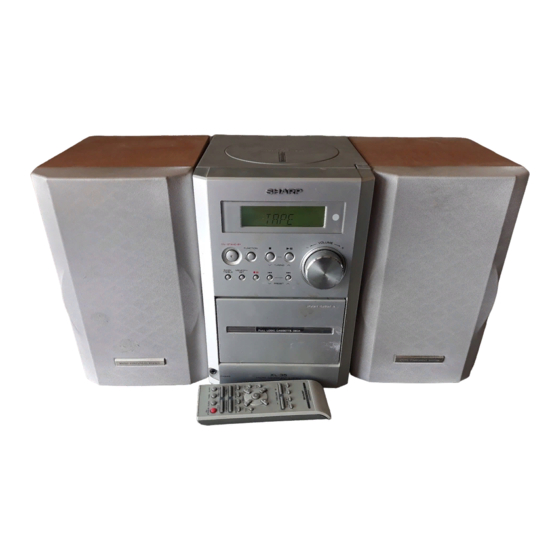
Illustration XL-35
IMPORTANT SERVICE NOTES (FOR U.S.A. ONLY) ..................................................................................................... 2
SPECIFICATIONS ............................................................................................................................................................ 2
NAMES OF PARTS .......................................................................................................................................................... 3
DISASSEMBLY ................................................................................................................................................................. 4
REMOVING AND REINSTALLING THE MAIN PARTS .................................................................................................... 5
ADJUSTMENT .................................................................................................................................................................. 7
TEST MODE ..................................................................................................................................................................... 8
ERROR LIST .................................................................................................................................................................. 12
NOTES ON SCHEMATIC DIAGRAM ............................................................................................................................. 13
TYPES OF TRANSISTOR AND LED .............................................................................................................................. 13
BLOCK DIAGRAM .......................................................................................................................................................... 14
SCHEMATIC DIAGRAM ................................................................................................................................................. 18
WIRING SIDE OF P.W.BOARD ...................................................................................................................................... 24
WAVEFORMS OF CD CIRCUIT ..................................................................................................................................... 29
TROUBLESHOOTING .................................................................................................................................................... 30
FUNCTION TABLE OF IC .............................................................................................................................................. 36
LCD SEGMENT .............................................................................................................................................................. 43
PARTS GUIDE/EXPLODED VIEW
SERVICE MANUAL
CONTENTS
SHARP CORPORATION
- 1 -
MICRO COMPONENT SYSTEM
MODEL
XL- 35 Micro Component System consisting of XL- 35 (main unit)
and CP- XL35 (speaker system).
MODEL
XL- 35C Micro Component System consisting of XL- 35C (main
unit) and CP- XL35 (speaker system).
• In the interests of user-safety the set should be restored to its original
condition and only parts identical to those specified should be used.
This document has been published to be used
for after sales service only.
The contents are subject to change without notice.
XL-35/35C
No. S1305XL35////
XL-35
XL-35C
Page
Advertisement
Table of Contents

Related Manuals for Sharp XL-35


Summary of Contents for Sharp XL-35
-
Page 1: Table Of Contents
XL-35C MODEL XL- 35C Micro Component System consisting of XL- 35C (main Illustration XL-35 unit) and CP- XL35 (speaker system). • In the interests of user-safety the set should be restored to its original condition and only parts identical to those specified should be used. -
Page 2: Important Service Notes (For U.s.a. Only)
XL-35/35C FOR A COMPLETE DESCRIPTION OF THE OPERATION OF THIS UNIT, PLEASE REFER TO THE OPERATION MANUAL. IMPORTANT SERVICE NOTES (FOR U.S.A. ONLY) BEFORE RETURNING THE AUDIO PRODUCT (Fire & Shock Hazard) Before returning the audio product to the user, perform the following safety checks. -
Page 3: Names Of Parts
XL-35/35C NAMES OF PARTS 1. CD Compartment 2. CD Eject Button 3. Volume Control 4. Cassette Compartment 5. Headphone Jack 6. Power On/Stand-by Button 7. Function Selector Button 8. CD or Tape Stop, Tuning Down Button 9. CD Play or Pause, Tape Play, Tuning Up Button 10. -
Page 4: Disassembly
XL-35/35C DISASSEMBLY Caution on Disassembly Follow the below-mentioned notes when disassembling (D2)x2 (D3)x1 the unit and reassembling it, to keep it safe and ensure Tape (D1)x1 excellent performance: Mechanism ø3x10mm 1. Take cassette tape and compact disc out of the unit. -
Page 5: Removing And Reinstalling The Main Parts
XL-35/35C (J1)x4 ø2.4x10mm (K1)x3 CD PWB ø2.6x10mm (J2)x1 ø2.6x10mm Top Cabinet Open/Close Top Cabinet Switch PWB (J3)x1 CD Mechanism (J3)x2 CD Mechanism Figure 5-2 Figure 5-1 REMOVING AND REINSTALLING THE MAIN PARTS TAPE MECHANISM SECTION (A2)x1 (A2)x1 ø2x7mm ø2x3mm Perform steps 1 to 5 and 8 of the disassembly method to remove the tape mechanism. -
Page 6: Cd Mechanism Section
XL-35/35C How to remove the flywheel (See Fig. 6-1.) (E1)x1 Stop Washer Mechanism 1. Remove the belt. Chassis 2. Remove the stop washer (E1) x 1 pc., with a small precision Stop Driver screwdriver to extract the flywheel from the capstan metal. -
Page 7: Adjustment
XL-35/35C ADJUSTMENT MECHANISM SECTION • Driving Force Check • FM Mute Level Signal generator: 1 kHz, 40 kHz dev., FM modulated Torque Meter Specified Value Frequency Display Adjusting Instrument Play: TW-2412 Over 80 g Parts Connection • Torque Check 98.00 MHz 98.0 MHz... -
Page 8: Test Mode
XL-35/35C • Setting the Test Mode Keeping the REW/REV button and BASS/TREBLE button pressed, turn on POWER. Then, the frequency is initially set in the memory as shown in Table. Call it with the PRESET button to use it for adjustment and check of tuner circuit. - Page 9 XL-35/35C * In case of initialization the pickup is moved toward the inner periphery. Any buttons other than POWER ON/STAND-BY button are not accepted until the shift of pickup to the inner periphery is completed at this time. If PU-IN SW ON cannot be detected within 10 seconds, the slide motor is stopped, and the following error indication appears.
- Page 10 XL-35/35C 5. Step 5 Mode The CD initialization operation flow is executed to the end, the mute is set to off, and playback is started. Even when the playback reaches the outermost periphery of disc, the operation does not stop. The LCD display indicates the playback past time as in case of ordinary CD playback.
- Page 11 XL-35/35C 3. Preset frequencies for various destinations (random preset memory) BAND Europe 2, 4 Europe 2, 4 BAND BAND Europe 2, 4 FM 87.50 MHz AM 531 kHz 16-25 FM108.00 MHz AM1602 kHz FM106.00 MHz FM 98.00 MHz AM 990 kHz FM 90.00 MHz...
-
Page 12: Error List
XL-35/35C 7. Key input diagnosis Test Mode (TEST 6) When the test mode is set, the following indication appears. This test mode is intended to check whether all the main unit buttons can be detected. Accordingly, in this test mode checking as to whether the "POWER ON/STAND-BY"... -
Page 13: Notes On Schematic Diagram
XL-35/35C NOTES ON SCHEMATIC DIAGRAM • Resistor: • The indicated voltage in each section is the one measured To differentiate the units of resistors, such symbol as K and by Digital Multimeter between such a section and the chas- M are used: the symbol K means 1000 ohm and the symbol sis with no signal given. -
Page 14: Block Diagram
XL-35/35C FM MUTE LEVEL SWITCHING T302 VR351 VD301-1 10K(B) AM TRACKING R_MUTE Q351 SVC348S AM OSC OUT X351 456kHz 14 13 IC303 T306 FM IF DET./FM MPX./AM IF AM OSC. VD301-2 SVC348S LA1832S CNP301 AM/FM ANTENNA TERMINALS AM IF T351... -
Page 15: Volume
XL-35/35C FM ST SO401 VIDEO/AUX IN R_MUTE TO DISPLAY AUX R CD+B P MUTE P-STB CNS704 P-CONTR WOOFER REC R CH R-CH OUT TAPE R TUN R CD R IC401 LOGIC LC75342M FUNCTION/VOLUME EQUALIZER A_12V CD L TUN L TAPE L... -
Page 16: Key Sw707-Sw709
XL-35/35C CNS605 TO MAIN SECTION CNP605 LCD701 SW801 CD LID OPEN/CLOSE CNP702 COM3 CLID SW CLID_SW CD STB COM0 MCLK MRST MDATA MCLK X701 BLBCK 8MHz STAT X702 MDATA CD_STB 32.768MHz SW702-SW704 IC701 SW707-SW709 MRST BLKCK KEY1 IX0060SJ SW705,SW706 PU_IN... - Page 17 XL-35/35C CNS605 CD_L A_GND CD_R TO MAIN SECTION D_GND CNP605 CD_6.2V M_GND D_GND CONSTANT SW801 VOLTAGE CD LID CD_6.2V OPEN/CLOSE Q804 X803 16.93MHz +6.2V DVDD1 M_GND MCLK CNP702 MDATA CLID SW IC801 AVSS2 CD STB MN6627482W AVDD2 MRST SERVO/SIGNAL CONTROL...
-
Page 18: Schematic Diagram
XL-35/35C IC303 LA1832S FM IF DET./FM MPX./AM IF C374 R363 AM ANT AM TRACKING FM MUTE LEVEL 0.022 6.8K VR351 4.7V T302 (0V) R361 L353 D301 C371 0.022 C329 1N4148 1/50 R362 AM BAND COVERAGE fL C372 1/50 D302 24 23... - Page 19 XL-35/35C MAIN PWB-A1 CNP704 SO401 R406 STEREO AUX R FM ST R-CH C408 10/16 VIDEO/AUX IN C406 10/16 R405 C404 10/16 L-CH C402 10/16 R416 CD+B R410 P MUTE WOOFER P-STB C340 C413 0.001 0.001 CD L C401 10/16 TUN L...
-
Page 20: Sw700
XL-35/35C LED PWB-A4 D708 D707 D709 MPG3372X MPG3372X MPG3372X R7D8 R7D3 R7D5 D704 D705 D706 MPG3372X MPG3372X MPG3372X R7D9 R7D6 R7D1 D702 D701 D703 MPG3372X MPG3372X MPG3372X R7E1 R7D2 R7D4 CFW701 SW707 REC/ PAUSE R708 SW708 <<REW PRESET DOWN R709 SW709 5.6K... - Page 21 XL-35/35C DISPLAY PWB-A2 LCD701 93 92 91 90 89 88 87 86 85 84 83 82 81 80 79 78 77 76 SEG25 2.5V SEG26 2.5V SEG27 2.5V 2.5V SEG28 SEG29 2.5V SEG30 2.5V SEG31 2.5V CLID_SW SEG32 2.5V CD_STB SEG33 2.5V...
- Page 22 XL-35/35C CD SERVO PWB-A3 SWITCH PWB-A6 SW801 CD LID OPEN/ CLOSE R823 1.8K R824 R825 5.6K R826 CD MOTOR PWB-C 6.3V 5.2V Q804 HSB562-C CNP803 CNW803 CNS803 NM802 SPINDLE SP– SP– – SL– SL– NM801 SLED MOTOR PU-IN PU-IN 1 2 3 4 5 6 7 8 9 10 11 12 13 14 –...
- Page 23 XL-35/35C CD SIGNAL CNP702 CLID_SW CD_STB R849 MRST MCLK MDATA BLKCK STAT PICK_IN GVSW R856 R845 R898 R899 C837 M_GND C849 6.2V R854 10/50 D_GND 20 19 18 17 16 15 14 13 12 11 10 CD_R R852 3.9K A_GND 5.1V...
-
Page 24: Wiring Side Of P.w.board
XL-35/35C R374 R373 X352 R391 C391 R372 R365 R392 C380 R371 CHASSIS C395 R385 R380 R359 R386 C387 R384 R360 C396 R382 C394 R387 L351 C376 ZD351 FM BAND C393 COVERAGE fL FM MUTE R309 C321 LEVEL C370 C378 C315... - Page 25 XL-35/35C MAIN PWB-A1 R106 Q105 B C E C110 Q106 R131 R111 B C E C391 R113 R132 C395 R112 R114 C111 C396 IC102 R103 12 10 8 6 4 2 D351 FROM DISPLAY PWB R126 C104 C103 P27 11 - E...
- Page 26 XL-35/35C TO MAIN POWER PWB-B CHASSIS CNW654 C660 C665 CNP707 C696 D688 CNP653 IC681 CNP652 C695 C688 C689 Q701 1 2 3 C683 R7A2 R7A1 R7A4 TO TAPE MECHANISM D652 CHASSIS C713 C704 C651 C652 R7A6 D651 F651 2.5A 125V...
-
Page 27: Sw700
XL-35/35C LED PWB-A4 CFW701A D701 D702 D703 D704 D705 D706 D707 D708 D709 R7D3 R7D4 R7E1 R7D1 R7D5 R7D9 R7D2 DISPLAY PWB-A2 Q701 C711 R750 Q702 1 2 3 R756 E C B R7A2 R747 R7A1 R748 B C E... - Page 28 XL-35/35C CNS605 TO MAIN PWB FROM DISPLAY PWB CNP605 P27 10 - G P25 7 - E CNS702 CFW807A R801 CNP702 CD SERVO PWB-A3 CNW805 R855 SW801 CD LID R854 CNW803 OPEN/CLOSE C825 IC801 R846 R822 C815 R826 C812 C805...
-
Page 29: Waveforms Of Cd Circuit
XL-35/35C WAVEFORMS OF CD CIRCUIT NO DISC FOCUS SEARCH CUE(TE) IC804 27pin IC801 27pin IC804 26pin IC804 3pin IC801 28pin IC801 33pin Figure 29-1 Figure 29-4 STOP PLAY(FE) REVIEW(TE) IC801 27pin RFDET IC801 38pin IC804 3pin IC801 44pin IC801 33pin... -
Page 30: Troubleshooting
XL-35/35C TROUBLESHOOTING When the CD does not function When the CD section does not operate when the objective lens of the optical pickup is dirty, this section may not operate. Clean the objective lens, and check the playback operation. When this section does not operate even after the above step is taken, check the following items. - Page 31 XL-35/35C Make sure that the disc is normal, and set the CD TEST MODE (STEP 1). Is the measured voltage as specified in circuit diagram? Check the main unit power supply circuit. Is "Er-CD01" displayed"? Move the pickup to most internal circumference side of disc.
- Page 32 XL-35/35C • Laser failure. Is +6.2V applied to the emitter of Q804 ? Check the PWB pattern between pin 5 of CNS605 and emitter of Q804. Check the peripheral parts of IC804 and Q804. Is +5V applied to the collector of Q804 ?
- Page 33 XL-35/35C • Focus servo sawtooth wave failure. IC801 is faulty. Is sawtooh wave output to the pin 28 (FOO) of IC801 ? 1.5~2.5sec Check the PWB pattern between pin 5 of CNS605 and IC804. Is +6.2V applied to the pins 21 and 22 (VCC) of IC804 ?
- Page 34 XL-35/35C • HF error. Is output (tracking error signal) obtained at the pins 33 (TE) Optical pickup failure. Is output obtained at the pins 2 and and 37 (TRCRS) of IC801 the CD TEST MODE "STEP 4" is 5 of CNS802 changed to "STEP 5"?
- Page 35 XL-35/35C • Track search failure Check as stated in item "SLED MOTOR OPERATION FAILURE". Does the sled motor run in FF/REW state when the SERVO TEST MODE "STEP1" is set? Is the following wave output to the pin 27 (TRO) of IC801 IC801 failure.
-
Page 36: Function Table Of Ic
XL-35/35C FUNCTION TABLE OF IC IC401 VHiLC75342M-1: Function/Volume Equalizer (LC75342M) Pin No. Port Name Function Serial data and clock input pin for control. Chip enable pin. Data written into an internal latch in a timing of [H] -> [L]. Each analog switch is activated. -
Page 37: Remote
XL-35/35C IC701 RH-iX0060SJZZ: System Control Microcomputer (IX0060SJ) (1/2) Terminal Name Input/Output Pin No. Function COM3-COM0 Output LCD common output terminal. VLC3-VLC1 — LCD power supply terminal. — Microcomputer power supply +5V. OSC2 Output Oscillator ground terminal for main clock. f=8MHz... - Page 38 XL-35/35C IC701 RH-iX0060SJZZ: System Control Microcomputer (IX0060SJ) (2/2) Terminal Name Input/Output Pin No. Function SEG46 P63/A3 Output Power IC amplifier detect. SEG45 P64/A4 Output Fan control. SEG44 P65/A5 Output SEG43 P66/A6 Output SEG42 P67/A7 Input CD pickup position detection SW input. "L" = Innerst periphery...
- Page 39 XL-35/35C IC801 VHiMN6627482W: Servo/Signal Control (MN6627482W) (1/2) Pin No. Terminal Name Input/Output Function BCLK Output SRDATA bit clock output. LRCK Output L/R identification signal output. SRDATA Output Serial data output. DVDD1 Input Digital circuit power supply. DVSS1 Input Digital circuit GND.
- Page 40 XL-35/35C IC801 VHiMN6627482W: Servo/Signal Control (MN6627482W) (2/2) Pin No. Terminal Name Input/Output Function DSLF Input/Output DSL loop filter terminal. PLLF Input/Output PLL loop filter terminal. VCOF Input/Output VCO loop filter terminal. AVDD2 Input Analog circuit power supply. (DSL, PLL and DA output sections for AD)
- Page 41 XL-35/35C IC801 VHiMN6627482W: Servo/Signal Control (MN6627482W) SUBCODE DSL • PLL VCO TIMING DIGITAL BUFFER DEEMPHSIS /RST GENERATOR /TEST PITCH CONTROL DEMODULATION 8TIMES CD-TEXT OVER BUFFER SYNC INTERPOLATION SAMPLING MICRO DIGITAL FILTER SUBCODE DEMODULATION COMPUTER RFENV INTERFACE CIRC ERROR CORRECTION 1 BIT DAC...
- Page 42 XL-35/35C IC802 VHiAN22000A-1: Head Amp. (AN22000A) Pin No. Terminal Name Function APC amp input. APC amp output. Power supply. RF amp inverting input. RFOUT RF addition amp output. RFIN AGC amp input. CAGC AGC loop filter connection. AGC output. Capacitor for HPF-amp connection.
-
Page 43: Lcd Segment
XL-35/35C LCD701: RV-LX0007SJZZ LCD Display 1 2 3 4 5 6 7 8 9 10 11 12 13 14 15 16 17 18 19 20 21 22 23 24 25 26 27 28 29 30 31 32 33 34 35 36 37 38 39 40 41 42... - Page 44 XL-35/35C –MEMO– – 44 –...
-
Page 45: Model Xl
“HOW TO ORDER REPLACEMENT PARTS” To have your order filled promptly and correctly, please furnish the For U.S.A. only following information. Contact your nearest SHARP Parts Distributor to order. 1. MODEL NUMBER 2. REF. No. 3. PART NO. 4. DESCRIPTION For location of SHARP Parts Distributor, Please call Toll-Free;... -
Page 46: Volume
XL-35/35C PRICE PRICE DESCRIPTION PARTS CODE DESCRIPTION PART CODE RANK RANK INTEGRATED CIRCUITS TRANSFORMERS IC101 VHIBA3126N/-1 AF Head Selector,BA3126N T302 RCILA0007SJZZ AG AM Tracking IC102 VHIBA3311L/-1 AK REC./P.B.Equalizer Amp., T304 RCILI0005SJZZ AF FM IF BA3311L T306 RCILB0009SJZZ AG AM OSC. - Page 47 XL-35/35C PRICE PRICE DESCRIPTION PART CODE PARTS CODE DESCRIPTION RANK RANK AA 0.001 µF,50V AB 47 µF,10V,Electrolytic C349 VCKYCY1HB102K C802 RC-GZA476AF1A AB 0.022 µF,25V AA 0.1 µF,25V C350,351 VCKYCY1EF223Z C803 VCKYCY1EF104Z AB 10 µF,16V,Electrolytic AB 47 µF,10V,Electrolytic C352 RC-GZA106AF1C C804 RC-GZA476AF1A AB 0.022 µF,25V...
- Page 48 XL-35/35C PRICE PRICE DESCRIPTION PART CODE PARTS CODE DESCRIPTION RANK RANK R131 VRD-ST2CD472J AA 4.7 kohms,1/6W R702 VRS-CY1JB103J AA 10 kohm,1/16W R132 VRS-CY1JB472J AA 4.7 kohms,1/16W R705 VRD-ST2CD392J AA 3.9 kohms,1/6W R133 VRS-CY1JB102J AA 1 kohm,1/16W R706 VRD-ST2CD472J AA 4.7 kohms,1/6W...
-
Page 49: Sw700
GITAS0008SJSA AG Side Panel,Left CNP704 QCNCM068LSJZZ Plug,10Pin GITAS0009SJSA AG Side Panel,Right CNP707 QCNCM052BSJZZ J AB Plug,2Pin HBDGA1002SJSB AD SHARP Badge CNP803 QCNCM932FAFZZ J AC Plug,6Pin HDECQ0108SJSA AF Cassette Holder Window CNS703 QCNCW010KAWZZ J AD Socket,10Pin HDECQ0109SJSA AD CD Lid Window... -
Page 50: Remote
XL-35/35C PRICE DESCRIPTION PART CODE RANK SPEAKER BOX PART B3CPXL35 Speaker Box Ass’y,L-CH/R-CH PACKING PARTS (EXCEPT FOR U.S.A.) SPAKA0130SJZZ AE Packing Add.,Top SPAKA0131SJZZ AE Packing Add.,Bottom SPAKA0132SJZZ AE Side Pad,Set SPAKC0266SJZZ Packing Case [Except for Canada] SPAKC0267SJZZ Packing Case [For Canada]... - Page 51 XL-35/35C 307-3 307-1 307-2 702x2 NM802 NM801 306x2 SW800 PWB-C Figure 6 CD MECHANISM EXPLODED VIEW – 6 –...
-
Page 52: Sw700
XL-35/35C PWB-A6 PWB-A4 609x2 PWB-A2 MECHANISM 603x3 LCD701 PWB-A3 603x7 604x4 217 217-1, 217-2,217-3, 217-4,217-5,217-6, 217-7,217-8,217-9, 217-10,217-11 603x4 609x2 601x2 602x2 PWB-A1 Washer Provided with 235x2 SW700 231x2 PWB-B 235x2 608x3 Q607 PWB-A5 Q605 Q604 BELT CONNECTION Motor FF/REW Silicon... -
Page 53: Packing Of The Set (For U.s.a. Only)
XL-35/35C PACKING OF THE SET (FOR U.S.A. ONLY) Setting position of switches and knobs Tape Mechanism STOP Cassette Holder CLOSE CD Lid CLOSE Packing Add.,Top Polyethylene Bag,Set SPAKA0130SJZZ SPAKP0042SJZZ Label,Serial No. TLABN0280SJZZ Packing Add.,Bottom SPAKA0131SJZZ Label,Energy Star Label,Pop TLABZ0038SJZZ TLABM0070SJZZ... - Page 54 XL-35/35C –MEMO–...
- Page 55 XL-35/35C –MEMO–...
- Page 56 XL-35/35C © COPYRIGHT 2003 BY SHARP CORPORATION ALL RIGHTS RESERVED. No part of this publication may be reproduced, stored in a retrieval system, or transmitted in any form or by any means, electronic, mechanical, photocopying, recording, or otherwise, without prior written permission of the publisher.
Need help?
Do you have a question about the XL-35 and is the answer not in the manual?
Questions and answers