MTD 61 series Shop Manual

MTD 61 series Shop Manual

Horizontal shaft engines
Hide thumbs Also See for 61 series:
Table of Contents

Advertisement

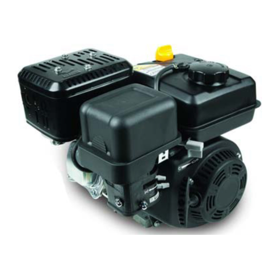
Professional Shop Manual
61/65/70/75 Series Horizontal Shaft Engines
NOTE: These materials are for use by trained technicians who are experienced in the service and repair of outdoor power
equipment of the kind described in this publication, and are not intended for use by untrained or inexperienced individuals.
These materials are intended to provide supplemental information to assist the trained technician. Untrained or inexperi-
enced individuals should seek the assistance of an experienced and trained professional. Read, understand, and follow all
instructions and use common sense when working on power equipment. This includes the contents of the product's Oper-
ators Manual, supplied with the equipment. No liability can be accepted for any inaccuracies or omission in this publication,
although care has been taken to make it as complete and accurate as possible at the time of publication. However, due to
the variety of outdoor power equipment and continuing product changes that occur over time, updates will be made to these
instructions from time to time. Therefore, it may be necessary to obtain the latest materials before servicing or repairing a
product. The company reserves the right to make changes at any time to this publication without prior notice and without
incurring an obligation to make such changes to previously published versions. Instructions, photographs and illustrations
used in this publication are for reference use only and may not depict actual model and component parts.
© Copyright 2013 MTD Products Inc. All Rights Reserved
MTD Products Inc. - Product Training and Education Department

Advertisement

Table of Contents
loading
Need help?

Need help?

Do you have a question about the 61 series and is the answer not in the manual?

Questions and answers

Subscribe to Our Youtube Channel

Summary of Contents for MTD 61 series

  • Page 1 Instructions, photographs and illustrations used in this publication are for reference use only and may not depict actual model and component parts. © Copyright 2013 MTD Products Inc. All Rights Reserved MTD Products Inc. - Product Training and Education Department...
  • Page 3: Table Of Contents

    Table of Contents Chapter 1: Introduction Professional Service Manual Intent ..............1 Safety ........................ 1 Fasteners ......................3 Assembly instructions ..................3 Model and serial number .................. 5 Maintenance ..................... 5 Spark plugs ....................... 6 Air filter ......................7 Oil type and capacity..................8 Changing the oil ....................
  • Page 4 Chapter 4: The Fuel System and Governor Fuel Line ......................41 Inspect the fuel lines ..................41 Inspecting the fuel................... 42 Test fuel for alcohol ..................42 Fuel filter ......................43 Fuel tank vent ....................44 To test the cap vent ..................44 The fuel tank ....................
  • Page 5 Chapter 7: Ignition System 81 Troubleshooting the ignition system ............... 81 Stop switch ..................... 82 Remote (ignition) stop switch ................. 83 The module ....................85 Module removal ....................86 Installing the module and setting the air gap ..........86 Flywheel ......................87 The spark plug ....................
  • Page 7: Chapter 1: Introduction

    • Common sense in operation and safety is assumed. • In no event shall MTD be liable for poor text interpretation or poor execution of the procedures described in the text. • If the person using this manual is uncomfortable with any procedures they encounter, they should seek the help of a qualified technician or MTD Technical Support.
  • Page 8 61/ 65/70/75 Series Horizontal Shaft Engines • Be prepared in case of emergency: ! CAUTION ! CAUTION Keep a fire extinguisher nearby Keep a first aid kit nearby Keep emergency contact numbers handy • Replace any missing or damaged safety labels on shop equipment. •...
  • Page 9: Fasteners

    Introduction Fasteners • Most of the fasteners used on the MTD engine are metric. Some are fractional inches. For this reason, wrench sizes are frequently identified in the text, and measurements are given in U.S. and metric scales. • If a fastener has a locking feature that has worn, replace the fastener or apply a small amount of releas- able thread locking compound such as Loctite®...
  • Page 10 61/ 65/70/75 Series Horizontal Shaft Engines MTD Horizontal Engine Model Designators 1 6 1 - S H A Starter/Alternators Major Revision 1=Recoil start Change 2=Electric start Compliance 3=E. start/alt. 20W/20W United States (50 State) 4=E. start/alt. 3A DC/5A Europe California...
  • Page 11: Model And Serial Number

    Introduction Model and serial number The model and serial number can be found on a white sticker with a bar code. The sticker is usually located at the base of the engine, under the valve cover. See Figure 1.1. Model number Figure 1.1 NOTE: The serial number will always start with the model number.
  • Page 12: Spark Plugs

    Cleaning the spark plug: NOTE: MTD does not recommend cleaning spark plugs. Use of a wire brush may leave metal deposits on the insulator that causes the spark plug to short out and fail to spark. Use of abrasive blast for cleaning may cause damage to ceramic insulator or leave blast media in the recesses of the spark plug.
  • Page 13: Air Filter

    MTD engine. See Figure 1.3. • Air filters used on the MTD engine are designed to prevent particles larger than 3-5 micron from passing through into the engine.
  • Page 14: Oil Type And Capacity

    Oil type and capacity The recommended oil for MTD engines is an SAE 10W-30 oil for summer engines and SAE 5W-30 for snow engines. Both oils should have a SM API rating or better. The oil capacity is 17.0- 20.3 fl.oz (0.5-0.6 liters).
  • Page 15 Introduction NOTE: There are two types of dip sticks that can be found on MTD engines; a threaded dip stick that was used on older engines and a quarter turn dip stick that is used on engines currently being produced.
  • Page 16: Changing The Oil

    61/ 65/70/75 Series Horizontal Shaft Engines Changing the oil NOTE: If the engine has been running, allow the engine to cool before doing any mainte- nance work. Siphon NOTE: The oil should be changed after the first 5 hours of operation and every 25 hours there after.
  • Page 17: Fuel System

    Introduction Fuel system What you should know about fuel. Most of the fuel presently available in North America is oxygenated to some extent. This is commonly done through the addition of ethanol. Most engines offered for sale on outdoor power equipment in the North American markets are designed to tolerate no more than 10% ethanol by volume Ethanol is hygroscopic, meaning it absorbs water.
  • Page 18 61/ 65/70/75 Series Horizontal Shaft Engines Install a new filter by following the above steps in reverse order. NOTE: Apply a small amount of a thread sealing compound such as Loctite® 564 and tighten the filter by hand and the an additional 3/4 to 1 full turn.
  • Page 19: Valve Lash

    Introduction Valve lash Valve lash is the clearance between the top of the valve stem and the rocker arm. The valve lash should be checked after the first 25 hours of use and every 100 hours after that. Valve lash can be checked and adjusted using the following steps:.
  • Page 20 61/ 65/70/75 Series Horizontal Shaft Engines 61/65/70 series engines 0.004” feeler gauge Check valve lash between each valve stem and rocker arm using a feeler gauge. Intake valve lash should be 0.004” - 0.006” (0.10 - 0.15 mm). See Figure 1.14. Setting intake valve lash Figure 1.14 0.006”...
  • Page 21 Introduction 75 series engines Check valve lash between each valve stem and rocker arm using a feeler gauge. Feeler gauge 6a. Intake valve lash should be 0.004” - 0.006” (0.10 - 0.15 mm). See Figure 1.16. Figure 1.16 6b. Exhaust valve lash should be 0.006” - 0.008” (0.15 - 0.20 mm).
  • Page 22: Exhaust System

    61/ 65/70/75 Series Horizontal Shaft Engines Exhaust system The exhaust system is a frequently overlooked component of an engine. It is important to make sure the muffler is in good condition and free of blockage. NOTE: A blocked muffler will result in poor performance. If a muffler is completely blocked, the engine may not start.
  • Page 23: Chapter 2: Basic Troubleshooting

    Also check attachments for damage and make sure they are firmly mounted. Steps to troubleshooting NOTE: The steps and the order of the steps that follow are a suggested approach to troubleshooting an MTD engine. The technician does not necessarily have to follow them as described in this chapter.
  • Page 24 61/65/70/75 Series Horizontal Shaft Engines IV. Unusual exhaust tone There are tools that the technician can use in order to define the problem, such as: Interview the customer. 1a. Get a good description of their complaint. 1b. If it is an intermittent problem, verify what conditions aggravate the problem as best as possible. 1c.
  • Page 25: Identify Factors That Could Cause The Problem

    ASIC ROUBLESHOOTING Identify factors that could cause the problem This is the second step in the troubleshooting process. Crankshaft will not turn. A. Starter not working. This can be an electrical failure or a mechanical failure. The likely suspects are: A dead battery.
  • Page 26 61/65/70/75 Series Horizontal Shaft Engines Run the engine with a spark tester in-line between the spark plug wire and the spark plug or use an oscilloscope and see if the spark goes away at the same time the engine dies. II.
  • Page 27 ASIC ROUBLESHOOTING V. Makes unusual smoke when running a. Black smoke, usually heavy, usually indicates a rich air fuel mixture • Not enough air: air flow blockage or a partially closed choke. • Too much fuel: carburetor float or float valve stuck or metering / emulsion issues with the car- buretor.
  • Page 28 61/65/70/75 Series Horizontal Shaft Engines chirping noise. • Confirm with a compression test and leak-down test. e. Unusual exhaust tone Splashy or blatty • Splashy idle usually indicates a slight rich condition. • May indicate an exhaust blockage, usually slightly muffled. Backfire •...
  • Page 29: Repairing The Problem

    ASIC ROUBLESHOOTING Repairing the problem The third step in the troubleshooting process is to repair the problem. This step consists of: A. Form a diagnosis by using all of the information gathered from the troubleshooting that was performed. B. Physically perform the repair. The fourth, and hopefully final, step in the troubleshooting process is the follow through.
  • Page 30: Prime Test

    61/65/70/75 Series Horizontal Shaft Engines Prime test To perform a prime test: Prime the engine through the carburetor throat using a squirt bottle, filled with clean fresh gasoline. Make sure the throttle is in the run position. Attempt to start the engine. If the engine starts and runs long enough to burn the prime, the problem is effectively isolated to the fuel sys- tem.
  • Page 31 ASIC ROUBLESHOOTING Adjust the tester until the gauge’s needle is pointing to the set position. Connect the tester to the adapter. NOTE: If the engine rotates it was not at top dead center. Check the reading on the gauge. NOTE: If the reading is >15% pressure loss, investigate for the cause of the leak by: •...
  • Page 32: Compression Test

    61/65/70/75 Series Horizontal Shaft Engines Compression test To perform a compression test: NOTE: Compression should be in the range of 55 - 80 PSI (3.8 - 5.5 Bar). • Disconnect the high-tension lead from the spark plug and ground it well away from the spark plug hole. •...
  • Page 33: Pcv Testing

    The cause of this oil burning can be mistaken for a worn-out engine, if proper diagnosis (compression, leak-down, and case pressure) is not performed. Experimentation by MTD’s Training and Education Department has revealed the following characteristics of MTD engines: •...
  • Page 34: Troubleshooting Flow Charts

    61/65/70/75 Series Horizontal Shaft Engines Troubleshooting flow charts Ignition Troubleshooting Engine runs Engine will erratically or shuts not start off, restarts Check for spark Spark No Spark Replace spark plug Check for the correct spark plug Isolate engine from equipment and repeat test Check flywheel and key for Spark...
  • Page 35: Engine Operation Problems

    ASIC ROUBLESHOOTING Engine Operation Problems ENGINE KNOCKS OVERHEATS Associated equipment loose or Excessive engine loading improperly adjusted Check for excessive carbon in Low oil level or wrong viscosity oil combustion chamber Cooling air flow obstructed or Loose flywheel examine key, key way and proper flywheel nut torque clogged cooling fins Ignition timing or...
  • Page 36 61/65/70/75 Series Horizontal Shaft Engines Engine Operation Problems SURGES OR RUNS UNEVENLY EXCESSIVE OIL CONSUMPTION Fuel cap vent obstructed Oil level above full Dirty carburetor or air filter Wrong viscosity oil Carburetor improperly adjusted Excessive engine speed Governor sticking, binding or Engine cooling fins dirty causing improper RPM setting overheating...
  • Page 37 ASIC ROUBLESHOOTING Engine Operation Problems ENGINE VIBRATES ENGINE MISFIRES EXCESSIVELY Carburetor improperly adjusted Bent crankshaft Attached equipment out Wrong or fouled spark plug of balance Valves sticking or not Loose mounting bolts seating properly Ignition timing or If applicable counter balance not incorrect spark plug properly aligned Excessive carbon build up...
  • Page 38 61/65/70/75 Series Horizontal Shaft Engines Engine Operation Problems LACKS POWER BREATHER PASSING OIL Oil level too high Air intake obstructed Lack or lubrication or improper Excessive RPM or improper lubrication governor setting Damaged gaskets, seals Carburetor improperly adjusted or "O" rings Breather damaged, dirty or Exhaust Obstructed improperly installed...
  • Page 39: Chapter 3: Air Intake Systems

    CHAPTER 3: AIR INTAKE SYSTEMS MTD builds horizontal crank engines for snow blowers and chore performers. The differences between snow engines and chore engines are the muffler and the air intake system. Therefore the air intake system for the snow and chore engines will be discussed separately, as will the mufflers in a later chapter.
  • Page 40 61/65/70/75 Series Horizontal Shaft Engines Disconnect the wire from the ignition switch and the Remove these primer line from the primer button. screws Remove the two screws that fasten the upper heat- box housing to the lower housing and lift out the upper housing.
  • Page 41 NTAKE YSTEMS Pop primer line out of notch while working the Work the engine shroud off of the carburetor studs. shroud off NOTE: Be careful to pop the primer line out of the notch that secures it while working the engine shroud off. See Figure 3.6.
  • Page 42: Chore Engines

    Paper-pleated element Generally air filters come in two different types, a pleated-paper element or foam. A combination of the two are used on the MTD engine. See Figure 3.9. • Air filters used on the MTD engine are designed to prevent particles larger than 3-5 micron from passing through into the engine.
  • Page 43: Air Filter Base And Intake Elbow

    NTAKE YSTEMS Air filter base and intake elbow To remove the air filter base: Remove the air filter following the steps described in the previous section. Remove the two screws that hold the air filter base to the intake elbow. See Figure 3.12. Lift the base off of the elbow.
  • Page 44: Carburetor Insulator

    61/65/70/75 Series Horizontal Shaft Engines Carburetor Insulator When working around the fuel ! WARNING ! WARNING system, do not bring any sources of heat, spark, or open flame near the work area. Remove the intake elbow by following the previ- ously described steps.
  • Page 45 NTAKE YSTEMS Unhook the spark plug wire from the clip molded into the insulator plate. See Figure 3.18. Spark plug wire Clip Figure 3.18 NOTE: An insulator block separates the carburetor from the cylinder head. There is a gasket on each side of the insulator.
  • Page 46 61/65/70/75 Series Horizontal Shaft Engines...
  • Page 47: Chapter 4: The Fuel System And Governor

    NOTE: When working on the fuel systems, look at the whole system. A problem will rarely be isolated to one component. Fuel Line The fuel line used by MTD is GREENbar . This is NBR intermediate layer NBR inner liner a multi-layer fuel line that meets the current EPA guide- lines.
  • Page 48: Inspecting The Fuel

    This results in less power for the engine. A 10% ethanol (E10) mix is acceptable for MTD engines. Anything higher than that will result in perfor- Figure 4.2 mance issues.
  • Page 49: Fuel Filter

    YSTEM AND OVERNOR Fuel filter New style NOTE: The fuel filter is located in the fuel tank. It can be removed and cleaned with a can of carb cleaner or replaced Figure 4.4 To avoid personal injury or property damage, use extreme care in handling gasoline. Gaso- line is extremely flammable and the vapors are explosive.
  • Page 50: Fuel Tank Vent

    61/65/70/75 Series Horizontal Shaft Engines Fuel tank vent The fuel tank vent performs the important task of allow- ing air into the fuel tank. As fuel is being used by the engine, the fuel level in the tank drops. The dropping fuel level then creates a vacuum in the tank.
  • Page 51: The Fuel Tank

    YSTEM AND OVERNOR The fuel tank To remove the fuel tank: Drain the tank. Disconnect the fuel line from the tank by following the steps described in the fuel filter section of Chapter 1: Introduction. Remove the dip stick Dip stick tube cover Remove the dip stick tube cover by removing the two screws.
  • Page 52 61/65/70/75 Series Horizontal Shaft Engines Remove the bolt securing the fuel tank mounting tab to the cylinder block. See Figure 4.11. Install the fuel tank by following the above steps in reverse order. Remove this bolt Figure 4.11...
  • Page 53: Choke

    YSTEM AND OVERNOR Choke MTD engines are equipped with a choke, a primer or both. If equipped with a manual choke, it must be closed to start the engine. The choke should be opened when the engine starts. This can be a source of starting issues with customers who are not familiar with manual chokes.
  • Page 54: Choke Linkage

    61/65/70/75 Series Horizontal Shaft Engines Choke linkage The rod connecting the choke knob to the choke plate on the carburetor can be bent slightly to facilitate adjust- Choke linkage ment. To access it: Remove the choke knob and the engine shroud by following the steps described in Chapter 3: Air Intake Systems.
  • Page 55: Primers

    YSTEM AND OVERNOR Primers MTD engines use a dry bulb primer. This means that there is no fuel in the primer bulb. The primer works by pushing air into the float chamber of the carburetor when the primer bulb is depressed. This will force fuel to be...
  • Page 56: Evaporative (Evap) Emissions System

    61/65/70/75 Series Horizontal Shaft Engines Evaporative (EVAP) emissions system NOTE: Gasoline is made from the graduated distillation of crude oil. It consists of a multitude of individual hydrocarbons and has a boiling range of 86 - 410 F (30-210 . The large quantity of hydrocarbons and the low boiling range makes gasoline an ideal fuel for spark ignited, internal combustion engines.
  • Page 57: Troubleshooting The Evap System

    YSTEM AND OVERNOR Troubleshooting the EVAP system NOTE: Troubleshooting a charcoal canister fuel cap is the same as troubleshooting a non-EVAP system. Symptom Cause Fuel leaking from the A blockage in the charcoal carburetor throat or canister or between the vents canister and the tank.
  • Page 58: Roll Over Valve Vent

    61/65/70/75 Series Horizontal Shaft Engines Roll over valve vent To remove/replace the roll over valve: Gently pry the roll over valve out of the fuel tank. See Figure 4.19. Inspect the rubber grommet, replace if damaged. Disconnect the vacuum line. NOTE: if the roll over valve is being removed to remove/replace the fuel tank, the vacuum line can remain attached.
  • Page 59: Charcoal Canister

    YSTEM AND OVERNOR Charcoal canister To remove/replace the charcoal canister: Remove the air filter. Charcoal canister Remove the two screws that hold the air filter base to the elbow using a #2 Phillips screw driver. See Figure 4.22. Lift the base off of the elbow enough to gain access to the vacuum lines underneath it.
  • Page 60: Testing A Charcoal Canister

    61/65/70/75 Series Horizontal Shaft Engines Testing a charcoal canister To test for a plugged charcoal canister: Remove the charcoal canister by following the pro- cedures described in the previous section of this chapter. Attach a vacuum pump to the smallest nipple of the canister.
  • Page 61: Carburetors

    YSTEM AND OVERNOR Carburetors If diagnosis indicates a fuel problem, inspect the carburetor. This is important even if problems are identified else- where in the fuel system.. IMPORTANT: the fuel must be tested for alcohol content before diagnosing anything else on the engine. NOTE: It is important to perform a compression or leak down test before condemning a carburetor.
  • Page 62 61/65/70/75 Series Horizontal Shaft Engines Float bowl Remove the bowl bolt using a 10mm wrench. See Figure 4.28. Drain bolt NOTE: From this point an assessment can be made Flat fiber about the viability of rebuilding the carbure- gasket Bowl bolt tor.
  • Page 63 YSTEM AND OVERNOR Main jet Bowl gasket Remove the main jet using a narrow-shank straight blade screwdriver. See Figure 4.31. NOTE: Fuel enters the central column through a port about 1/2” (1cm) from the bottom, to help prevent the ingress of any residue in the bottom of the bowl.
  • Page 64 61/65/70/75 Series Horizontal Shaft Engines Carefully pry out the metering plug using a small screwdriver. See Figure 4.34. Figure 4.34 Examine the metering plug: See Figure 4.35. Air passage End view NOTE: The transition ports are fixed. They are drilled into the throat of the carburetor, down-stream of the venturi.
  • Page 65: Governor

    YSTEM AND OVERNOR Governor The engine speed is controlled by a balance between the force applied by a spring (pulling the throttle open) and a flyweight mechanism within the engine applying force to the governor arm (pushing the throttle closed). Governor action See Figure 4.37.
  • Page 66: Governor Shaft

    61/65/70/75 Series Horizontal Shaft Engines Governor shaft To remove or replace the governor shaft: Remove the engine from the equipment that it pow- ers. Remove the governor arm by following the previ- ously described steps. Remove the flywheel by following the steps described in Chapter 7: Ignition Systems.
  • Page 67: Governor Cup And The Governor Gear

    YSTEM AND OVERNOR Governor cup and the governor gear To remove or replace the governor gear and cup: Remove the engine from the unit. Remove the governor arm by following the previously Governor gear shaft described steps. Remove the flywheel by following the steps described in Chapter 7: Ignition Systems.
  • Page 68 61/65/70/75 Series Horizontal Shaft Engines NOTE: A second thrust washer goes between the Thrust washer governor gear and the cylinder block. Make sure it is in place when installing the gover- nor gear. See Figure 4.44. Install the governor gear and cup by following the above steps in reverse order.
  • Page 69: Chapter 5: Lubrication

    Lubrication CHAPTER 5: LUBRICATION Oil type and quantity The recommended oil for MTD engines is an SAE 10W-30 oil with an SM API rating or better. The oil capacity is 17.0- 20.3 fl.oz (0.5-0.6 liters). 14°F 32°F 50°F 68°F 86°F 104°F...
  • Page 70: Oil Dip Stick

    61/65/70/75 Series Horizontal Shaft Engines Oil dip stick To check the oil level: NOTE: Be sure to check the engine on a level sur- Dip stick face with the engine stopped. Remove the oil filler cap and wipe the dipstick clean. Insert the dipstick into the engine block, but do not screw it in.
  • Page 71: Dip Stick Tube Removal

    Lubrication Dip stick tube removal To remove/replace the dip stick tube: Remove these Remove the dip stick. screws Remove the two screws securing the dip stick cover in place using a #2 Phillips screw driver. See Figure 5.3. Figure 5.3 Remove the screw at the bottom of the dip stick tube.
  • Page 72: Lubrication System

    61/65/70/75 Series Horizontal Shaft Engines Lubrication system MTD uses a splash lube system for it’s horizontal shaft engines. The connecting rod has a dipper on it that “splashes” oil around the inside of the engine. See Figure 5.6. Dipper Figure 5.6 NOTE: The cam and tappets were removed for bet- ter visualization of the lubrication system.
  • Page 73: Positive Crankcase Ventilation Valve

    Lubrication Positive crankcase ventilation valve The PCV valve is located inside the valve cover. The Breather hose function and test procedures for the PCV valve is covered in Chapter 2: Basic Troubleshooting. To remove the valve cover and PCV valve: Disconnect and ground the spark plug wire.
  • Page 74 61/65/70/75 Series Horizontal Shaft Engines...
  • Page 75: Chapter 6: Starter And Charging Systems

    Starters CHAPTER 6: STARTER AND CHARGING SYSTEMS Recoil Starter Removal To remove recoil assembly from the engine: Remove the three nuts that secure the recoil assem- bly to the engine using a 8mm wrench. See Figure 6.1. Remove these screws Install the starter by following the above step in reverse order.
  • Page 76 61/65/70/75 Series Horizontal Shaft Engines Starter cup dimple Install a starter cup by placing it on the flywheel, with the dimple on the bottom of the starter cup in the dimple in the flywheel. See Figure 6.3. Install the flywheel nut and tighten it to a torque of 47 - 52 ft-lbs (64 - 70 Nm).
  • Page 77: Starter Rope

    Starters Starter Rope The most common failure mode for most recoil assem- Rope inserted blies is a broken rope. from the inside NOTE: If the spring was not damaged when the recoil sprung back, It is possible to simply remove the remnants of the old rope and install a new rope.
  • Page 78: Starter Pulley And Recoil Spring

    61/65/70/75 Series Horizontal Shaft Engines Starter pulley and recoil spring The recoil spring is nested within the starter pulley and both parts are sold as a single part number. Eye protection should be worn if the starter pulley is to be removed. ! CAUTION ! CAUTION The recoil spring is under tension and can release as the pulley is removed.
  • Page 79 Starters Pulley Housing Carefully lift the spring and pulley out of the recoil housing. See Figure 6.9. NOTE: If the spring is undamaged, but has been removed from the pulley, the spring may be re-wound. Hook the end of the spring into the slot in the outer lip of the recess of the pulley and wind the spring into the recess in a counter-clockwise direction.
  • Page 80: Electric Starter

    61/65/70/75 Series Horizontal Shaft Engines Electric starter The electric starter is only available on the snow engine. It is powered by an extension cord that is plugged into household 120 volt AC current. The starter and switch assembly are one piece and are not serviceable. Remove these screws To replace the starter assembly: Disconnect the extension cord.
  • Page 81: Electric Starter Switch

    Starters Electric starter switch To remove/replace the electric starter switch assembly: Cut the cable tie that secures the alternator harness to the starters power cord. See Figure 6.13. Cable tie Remove the two screws that hood the switch box assembly to the engine using a #2 Phillips screw- driver.
  • Page 82 61/65/70/75 Series Horizontal Shaft Engines Disconnect the ground wire from the end cap. See Ground wire Figure 6.16. Remove the O-ring. Lift the harness and grommet out of the end cap. Figure 6.16 Install a new O-ring on the front cover that is still attached to the engine.
  • Page 83 Starters 14. Install the thrust washer. See Figure 6.19. Thrust washer Figure 6.19 15. Press the harness’s grommet into the end cap. See Figure 6.20. Figure 6.20 Green wire 16. Attach the green wire to the end cap. 17. Install a new O-ring on the end cap. See Figure 6.21. NOTE: Applying grease to the O-ring groove will help hold the O-ring in place during assembly.
  • Page 84 61/65/70/75 Series Horizontal Shaft Engines Attach the white and black wires of the harness to the brush housing. See Figure 6.22. Figure 6.22 Set the end cap in place. 12 O’clock NOTE: The holes should be at the 6 & 12 O’clock positions.
  • Page 85: Charging System

    Starters Charging system Description Some engines are equipped with a charging system. Magnets The charging system consists of: • Alternator stator: copper field windings around an iron core. The stator is attached to the engine block beneath the flywheel. • Four magnets on the inside of the flywheel, refer to figure 6.13, that rotate around a stator that is mounted to the cylinder block.
  • Page 86: Stator

    61/65/70/75 Series Horizontal Shaft Engines Stator To remove/replace the stator: Remove these screws Remove and ground the spark plug wire. Remove the flywheel by following the steps described in Chapter 7: Ignition System. Remove the baffle that covers the charger harness using a 10mm wrench.
  • Page 87: Chapter 7: Ignition System

    Ignition System CHAPTER 7: IGNITION SYSTEM Troubleshooting the ignition system The purpose of the ignition system is to provide a spark in the combustion chamber at the proper time to ignite the fuel/air mixture. The steps in troubleshooting the ignition system are: Examine the spark plug(s) by following the steps described in the spark plug section of this chapter.
  • Page 88: Stop Switch

    MTD horizontal engines that are in use in North America have a stop switch built into the throttle lever assembly. MTD engines used on snow blowers have an additional stop (ignition) switch in the Disconnect switch engine shroud.
  • Page 89: Remote (Ignition) Stop Switch

    Ignition System Remote (ignition) stop switch To test the remote stop switch: Remove the muffler cover. Disconnect wires Disconnect the two wires from the remote switch. See Figure 7.5. Remote switch Figure 7.5 Connect a digital multimeter to the two tabs on the No Continuity back of the remote switch.
  • Page 90 61/65/70/75 Series Horizontal Shaft Engines Connect one lead of the multimeter to the blue wire that goes to the remote switch. Continuity Connect the other lead of the multimeter to a good ground. Blue wire Continuity Blue wire Set the multimeter to the ohms (Ω) scale. •...
  • Page 91: The Module

    Ignition System The module The coil in this ignition system is an inductive discharge magneto, contained in a single module. • The inductive discharge magneto has a two leg design. • The magneto is energized by the passing of a pair of magnets mounted in the flywheel. •...
  • Page 92: Module Removal

    61/65/70/75 Series Horizontal Shaft Engines Module removal Unplug the spark plug. Remove the Heat box (snow engines) and intake elbow by following the steps described in Chapter 3: Air Intake Systems. Unhook the spark plug wire from the clip in the car- buretor insulator.
  • Page 93: Flywheel

    A sheared flywheel key will throw off the ignition timing. They are uncommon on the MTD engine. If one is found, check for a bent crankshaft.
  • Page 94: The Spark Plug

    61/65/70/75 Series Horizontal Shaft Engines The spark plug • The spark plug is a F6RTC, part #951-10292, gapped to 0.024” - 0.031” (0.6 - 0.8 mm). • Wear rate will vary somewhat with severity of use. If the edges of the center electrode are rounded-off, or any other apparent wear / damage occurs, replace the spark plug before operating failure (no start) occurs.
  • Page 95: Chapter 8: Exhaust

    Exhaust CHAPTER 8: EXHAUST The exhaust system is a frequently overlooked component of an engine. It is important to make sure the muffler is in good condition and free of debris and/or insects. NOTE: A blocked muffler will result in poor performance. If a muffler is completely blocked, the engine may not start.
  • Page 96: To Remove/Replace The Muffler

    (if reusing the muffler). See Figure 8.4 Figure 8.5. NOTE: The MTD engine uses a graphite exhaust Remove all gasket material gasket. It is not reusable and must be replaced every time the muffler nuts are loosened.
  • Page 97: Snow Engines

    Clean all of the gasket material off of the cylinder head and the muffler (if reusing the muffler) NOTE: The MTD engine uses a graphite exhaust gasket. It is not reusable and must be replaced every time the muffler nuts are loosened.
  • Page 98 61/65/70/75 Series Horizontal Shaft Engines...
  • Page 99: Chapter 9: Cylinder Head

    Cylinder head CHAPTER 9: CYLINDER HEAD The Cylinder head of the MTD engine can be removed without removing the engine from the piece of equipment. To remove the cylinder head: Disconnect switch Disconnect and ground the spark plug high tension lead.
  • Page 100 61/65/70/75 Series Horizontal Shaft Engines Remove the muffler by following the steps Heat baffle described in Chapter 8: Exhaust. Remove the heat baffle. See Figure 9.3. Remove these screws Figure 9.3 Remove the four screws securing the valve cover using a 10mm wrench. See Figure 9.4. Remove valve cover Figure 9.4 Remove the rocker arms and push rods:...
  • Page 101 Cylinder head 75 Series heads A. Loosen the rocker jam nuts. B. Remove the rocker stud nuts. C. Lift the rockers and the carrier off as an assem- bly. D. Remove the push rods. NOTE: Once broken-in, the rocker arm should be kept with its corresponding valve.
  • Page 102 Graphite head the alignment dowels to hold it in place. See Figure gasket 9.9. NOTE: MTD uses graphite head gaskets that have a bead of silicon on them. They are not reus- able. Figure 9.9 Position the cylinder head on the engine block.
  • Page 103: Valves

    Cylinder head Valves Valves and valve parts, like springs and keepers, are not available as service parts. The valves and valve seats can be serviced by grinding and lapping or the head can be replaced. Depending on local machine and labor costs, it is probably more economical to replace the cylinder head versus servicing the valves.
  • Page 104 61/65/70/75 Series Horizontal Shaft Engines Lift the springs off of the valve stems. Slide the valves out of the cylinder head. NOTE: Only the intake valve has a valve guide seal. See Figure 9.13. Seal Figure 9.13 Inspect the valve seat. See Figure 9.14. •...
  • Page 105 Cylinder head Inspect the valve stem. See Figure 9.15. Inspect the valve springs. NOTE: Valve spring free length should be at least 1.22” (28.5mm). Original length is 1.44” (36.6mm). Install the valves in the cylinder head by following steps 2 - 5 in reverse order. Inspect for a Test the valves for leaks by: burnt edge...
  • Page 106: Push Rod Bushings

    Push rod bushings The MTD engine has bushings for the push rods that need to be replaced from time to time. An indication that the bushings are worn is that the valve lash loosens up. This is because the push rods start moving side to side which opens up the valve lash.
  • Page 107 Cylinder head NOTE: When installing a push rod bushing plate, make This side points up, towards sure the bushings extend away from the cylinder the valve cover. head. See Figure 9.18. Install by following the above steps in reverse order. NOTE: Tighten the rocker studs to a torque of 16 - 18 ft-lbs (22 - 25 Nm).
  • Page 108 61/65/70/75 Series Horizontal Shaft Engines...
  • Page 109: Chapter 10: Crankshaft, Piston And Connecting Rod

    Crankshaft, piston and connecting rod CHAPTER 10: CRANKSHAFT, PISTON AND CONNECTING ROD There are a a few different paths that can be followed when disassembling an engine. This chapter will cover the removal of components in one order, but it is written so that the technician can jump around, the exact method depends on the type of repair that needs to be made.
  • Page 110 61/65/70/75 Series Horizontal Shaft Engines Remove the camshaft. See Figure 10.2. Cam shaft Compression relief Remove the cam shaft Figure 10.2 Remove the valve tappets. See Figure 10.3. NOTE: Keep track of which tappet was originally riding on which lobe. Be sure there are reas- sembled that way.
  • Page 111 Crankshaft, piston and connecting rod Piston ring pliers 15. Push the piston out of the cylinder. 16. Remove the piston rings from the piston using a pair of piston ring pliers. See Figure 10.5. Figure 10.5 17. Remove the crank shaft. See Figure 10.6. Remove the crankshaft Figure 10.6...
  • Page 112: Crank Shaft Inspection

    61/65/70/75 Series Horizontal Shaft Engines Crank shaft inspection Bearing contact Inspect the crank shaft journals for galling, scoring, area pitting or any other form of damage. Measure the journals at the bearing contact points using a vernier caliper or a micrometer. See Figure 10.7.
  • Page 113: Piston Inspection

    Install the rings on the piston. Top piston ring NOTE: Typically there is a top and bottom profile to com- pression rings, But the compression rings on the MTD are symmetrical. See Figure 10.10. Middle piston ring 3-piece oil ring Figure 10.10...
  • Page 114: Connecting Rod Inspection

    61/65/70/75 Series Horizontal Shaft Engines Connecting rod inspection Inspect the connecting rod for cracks or any signs of Measure at damage. right angles Install the rod cap and tighten to a torque of 106 - 124 in lbs (12 - 14Nm). Measure the inside diameter of the connecting rod and compare the measurements to those listed in the chart at the end of this chapter.
  • Page 115: Cylinder Inspection

    Crankshaft, piston and connecting rod Cylinder inspection Measure the cylinder bore Clean and inspect the cylinder, inside and out. NOTE: If there is any sign of damage, especially cracked cooling fins, short block the engine. NOTE: Take two measurements of the cylinder bore 90 degrees apart at the top, bottom and middle of the cylinder.
  • Page 116: Bearings

    61/65/70/75 Series Horizontal Shaft Engines Bearings There are two bearings to inspect; a bearing in the crank case cover and one in the cylinder block. To inspect the bearings: Remove the crank case cover and cylinder block oil Seal puller seals using a seal puller.
  • Page 117: Reassembly

    Crankshaft, piston and connecting rod Reassembly Clean the cylinder 1a. Remove all gasket material from all mating sur- faces. 1b. Clean the cylinder and crank case cover. Oil seals Troy-Bilt seal driver 2a. Install a new oil seal in the cylinder block. 2b.
  • Page 118 61/65/70/75 Series Horizontal Shaft Engines arrow 4a. Compress the piston rings using a piston ring compressor. 4b. Pre-lube the cylinder wall with clean 10W-30 motor oil 4c. Slide the connecting rod and piston into the cyl- inder. NOTE: The arrow on the piston must point towards the push rod cavity.
  • Page 119 Crankshaft, piston and connecting rod Install the valve tappets. Install the cam shaft by: 6a. Pre-lube the cam shaft with clean 10W-30 motor oil 6b. Rotate the crank shaft until the timing mark points to the tappets. Insert the cam shaft while aligning the timing Timing marks marks.
  • Page 120: Engine Specifications Chart

    61/65/70/75 Series Horizontal Shaft Engines Engine specifications chart minimum maximum minimum maximum Displacement 7.5 cu in 123 cc 10.9 cu in 179 cc Bore 2.402 61.005 2.402 61.015 2.559 65.005 2.560 65.015 Stroke 1.654 42.000 1.654 42.000 2.126 54.000 2.126 54.000 Compression Ratio 8.7:1...
  • Page 121 Crankshaft, piston and connecting rod minimum maximum minimum maximum Cam shaft bearing ID 0.559 14.200 0.560 14.218 0.559 14.200 0.560 14.218 (sump) Intake lobe rise 0.213 5.400 0.228 5.800 0.213 5.400 0.228 5.800 Intake lobe base circle 0.433 11.000 0.433 11.000 0.433 11.000...
  • Page 122 61/65/70/75 Series Horizontal Shaft Engines minimum maximum minimum maximum Displacement 12.7 cu in 208cc 14.8cu in 243 cc Bore 2.756 70.000 2.756 70.010 2.953 75.000 2.953 75.010 Stroke 2.126 54.000 2.126 54.000 2.165 55.000 2.165 55.000 Compression Ratio 8.7:1 8.7:1 Cranking Pressure 40 - 70 psi (2.8 - 4.8 bar) 40 - 70 psi (2.8 - 4.8 bar)
  • Page 123 Crankshaft, piston and connecting rod minimum maximum minimum maximum Cam shaft bearing ID 0.559 14.200 0.560 14.218 0.559 14.200 0.560 14.218 (sump) Intake lobe rise 0.213 5.400 0.228 5.800 0.237 6.020 0.239 6.060 Intake lobe base circle 0.433 11.000 0.433 11.000 0.433 11.000...
  • Page 124: Engine Torque Values Chart

    61/65/70/75 Series Horizontal Shaft Engines Engine torque values chart Fastener Torque Blower housing 80 - 106 in lbs 80 - 106 in lbs 80 - 106 in lbs 80 - 106 in lbs (9-12 Nm) (9-12 Nm) (9-12 Nm) (9-12 Nm) Carburetor drain bolt 80 - 106 in lbs 80 - 106 in lbs...
  • Page 125: Chapter 11: Failure Analysis

    Failure Analysis CHAPTER 11: FAILURE ANALYSIS A properly maintained engine will provide years of service. Occasionally an engine will fail. An important part of working on engines is finding out why they failed. Was it something the customer did? Was it a manufacturing defect? Did the engine just wear out? All of these questions need to be answered when a failed engine is found.
  • Page 126 61/65/70/75 Series Horizontal Shaft Engines When particles enter the combustion chamber, the Cross hatch polished off up and down motion of the piston grinds the parti- cles into the side of the cylinder walls and damages the cylinder wall, piston and piston rings This can be identified by the scoring along the verti- cal axis of the piston and cylinder wall or the cross hatch on the cylinder wall being worn off.
  • Page 127 Failure Analysis Because the oil suspends the abrasive particles, the engine components that are immersed in oil will show definite signs of abrasive ingestion especially around the connecting rod and main bearing journals. See Figure 11.5. NOTE: Abrasives that are trapped in the oil will cause the lower portion of the combustion chamber to wear- ing more than the upper portion.
  • Page 128: Insufficient Lubrication

    61/65/70/75 Series Horizontal Shaft Engines Insufficient lubrication The bearing surfaces in an engine are not smooth. As a result of the machining processes to make the engine parts, there are little peaks and valleys that are only visible on a microscopic scale. These peaks are called asperi- ties.
  • Page 129: Engine Overspeed

    Generally speaking this is at the narrowest part of the connecting rods. On most engines that would be about an inch below the wrist pin, but on the MTD engine it is at the wrist pin.
  • Page 130: Overheated

    Overheated The MTD engines are air cooled engines. Because of this, cleanliness of the engine is very important to the life of the engine. Dirt, grass and sludge all form an insulating layer on the engine. This will trap the heat in the engine and cause it to over heat.
  • Page 131: Mechanical Breakage/ Wear

    Failure Analysis Mechanical Breakage/ Wear Sometimes an engine fails because a part breaks. There are generally three causes of a broken part, outside of the previously discussed engine failures. They are abuse, wear, and manufacturing defects. Bent blade A very common way to abuse an engine is a bent crank shaft.
  • Page 132 61/65/70/75 Series Horizontal Shaft Engines...
  • Page 134 MTD Products Inc - Product Training and Education Department FORM NUMBER - 769-04015-01 07/2013...

This manual is also suitable for:

65 series70 series75 series

Table of Contents

Save PDF