Heatilator A36C Owner's Manual
Installation and operation
Hide thumbs
Also See for A36C:
- Owner's manual (51 pages) ,
- Installation manual (40 pages) ,
- Owner's manual (24 pages)
Table of Contents
Advertisement
Quick Links
Models:
A36C, A36CH
A42C, A42CH
Woodburning Fireplace
•
Important operating
a n d m a i n t e n a n c e
instructions included.
WARNING
If the information in these instruc-
tions is not followed exactly, a
fi re may result causing property
damage, personal injury, or death.
• Do not store or use gasoline or other fl am-
mable vapors and liquids in the vicinity of
this or any other appliance.
• Do not overfi re. Overfi ring will void your
warranty.
• Comply with all minimum clearances to
combustibles as specifi ed. Failure to
comply may cause house fi re.
Installation and service of this fi replace should
be performed by qualifi ed personnel. Hearth
& Home Technologies suggests NFI certifi ed
or factory-trained professionals, or technicians
supervised by an NFI certified
professional.
CAUTION
DO NOT DISCARD THIS MANUAL
•
Read, understand
and follow these
instructions for safe
i n s t a l l a t i o n a n d
operation.
Heatilator • A36C & A42C • 28396 Rev Y • 10/06
Owner's Manual
Installation and Operation
•
Leave this manual with
party responsible for
use and operation.
WARNING
HOT! DO NOT TOUCH.
SEVERE BURNS MAY RESULT.
CLOTHING IGNITION MAY RESULT.
Glass and other surfaces are hot
during operation and cool down.
•
Keep children away.
•
CAREFULLY SUPERVISE children in same room
as fi replace.
•
Alert children and adults to hazards of high
temperatures.
•
Keep clothing, furniture, draperies and other
combustibles away.
WARNING
Fire Risk
•
For use with solid wood fuel or decorative
gas appliance only.
•
Do not install unvented gas logs.
1
Advertisement
Table of Contents

Related Manuals for Heatilator A36C


Summary of Contents for Heatilator A36C
-
Page 1: Woodburning Fireplace
For use with solid wood fuel or decorative or factory-trained professionals, or technicians gas appliance only. supervised by an NFI certified • Do not install unvented gas logs. professional. Heatilator • A36C & A42C • 28396 Rev Y • 10/06... - Page 2 IF INSTALLATION OR OPERATING INSTRUCTIONS ARE MISSING DECORATIVE GAS APPLIANCE IN THE FIREPLACE, CONTACT: HEARTH & HOME TECHNOLOGIES INC., ADJUST DAMPER TO THE FULLY OPEN POSITION. 1915 W. SAUNDERS ST., MT. PLEASANT, IA 52641. Heatilator • A36C & A42C • 28396 Rev Y • 10/06...
-
Page 3: Table Of Contents
C. Installation of Fan......25 Note: An arrow ( ) found in the text signifi es change in content. Heatilator • A36C & A42C • 28396 Rev Y • 10/06... -
Page 4: Listing And Code Approvals
Installation and/or use of any component part not approved by Hearth & Home Technologies. Hearth & Home Technologies disclaims any responsibility for, and the warranty and agency listing will be voided by the above actions. Heatilator • A36C & A42C • 28396 Rev Y • 10/06... -
Page 5: Getting Started
Basement installations should be avoided due to stack effect. Stack effect creates negative pressure in lower levels. Hearth & Home Technologies recommends the use of direct vent fi replaces in basements. Heatilator • A36C & A42C • 28396 Rev Y • 10/06... - Page 6 Consider the fi replace location relative to fl oor and ceiling and attic joists. Recommended Recommended Location Location Marginal Location Location Recommended Location Recommended Windward Outside Air Intake Leeward Multi-level Roofs Figure 2.1 Recommended Chimney Locations Heatilator • A36C & A42C • 28396 Rev Y • 10/06...
-
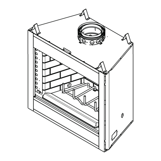
Page 7: Typical Fireplace System
V-shaped standoffs (spacers) Mantel and surround Decorative facing and trim Hearth extension Outside combustion air Factory-built fireplace Protective metal hearth strip(s) Figure 2.2 Typical Fireplace System Heatilator • A36C & A42C • 28396 Rev Y • 10/06... -
Page 8: Tools And Supplies Needed
Read all the instructions before starting the installation. Follow these instructions carefully during the • Keep fi replace dry. installation to ensure maximum safety and benefi t. • Mold or rust may cause odors. Heatilator • A36C & A42C • 28396 Rev Y • 10/06... -
Page 9: Framing And Clearances
Model # outside air) outside air) outside air) 71-1/2 35-3/4 15-3/4 50-5/8 1194 1092 1816 1286 1092 77-1/2 38-7/8 54-7/8 1346 1245 1969 1394 1245 Figure 3.1 Fireplace Locations Heatilator • A36C & A42C • 28396 Rev Y • 10/06... -
Page 10: Clearances
3/4 in. (19 mm) to side of appliance 0 in. (except at nailing flanges where it is 1/2 in. [13 mm]) to floor Figure 3.2 Clearances to Combustible Materials Heatilator • A36C & A42C • 28396 Rev Y • 10/06... -
Page 11: Sidewalls/Surrounds
41-1/2 in. Use only noncombustible (1055 mm) material below the top of the front standoffs. 23 in. (584 mm) Model # 1092 1245 Figure 3.4 Framing the Fireplace Heatilator • A36C & A42C • 28396 Rev Y • 10/06... -
Page 12: Construct The Chase
fi replace • Maximum unsupported chimney above roof 6 ft (1.83 m) Figure 3.5 Chase Assembly Note: A maximum of two pairs of offsets and returns may be used. Heatilator • A36C & A42C • 28396 Rev Y • 10/06... -
Page 13: Installation Of Fireplace
The outside air kit is installed on the left hand side of the fi replace. See Figure 4.4 for handle location/operation. Flexible Duct (not supplied) 2 Wire Ties Outside Outside Air Collar Air Shield Figure 4.1 Outside Air Installation Heatilator • A36C & A42C • 28396 Rev Y • 10/06... - Page 14 (preferably with short run or mainly straight duct, except small dip for cold air trap which will help prevent flow of cold air). Figure 4.3 Outside Combustion Air Placement Heatilator • A36C & A42C • 28396 Rev Y • 10/06...
-
Page 15: Secure The Fireplace
fi replace opening for square. Measure diagonal dis- tances of the opening to make sure they are equal. If they are not, continue to shim the fi replace until those diagonals are equal. Heatilator • A36C & A42C • 28396 Rev Y • 10/06... -
Page 16: Chimney Assembly
Figure 5.1 Typical Chimney System - Guidelines for Chimney System Installation NOTE: • Chimney performance may vary. • Trees, buildings, roof lines and wind conditions affect performance. • Chimney height may need adjustment if smoking or overdraft occurs. Heatilator • A36C & A42C • 28396 Rev Y • 10/06... -
Page 17: Chimney Requirements
• Do NOT connect to any air distribution duct or SL318 16-3/4 system. SL324 22-3/4 SL336 34-3/4 SL348 46-3/4 1187 * Dimensions refl ect effective height. Heatilator • A36C & A42C • 28396 Rev Y • 10/06... -
Page 18: Using Offsets/Returns
fi ts your application is Proper assembly of air-cooled chimney parts result in an overlap at chimney joints of 1-1/4 in. (32 mm). Effective one SL324. length is built into this chart. Heatilator • A36C & A42C • 28396 Rev Y • 10/06... -
Page 19: Assemble The Chimney Sections
fl oor or every 10 ft (3.05 m) of clear space. • Use same dimensional lumber as joists. Ceiling fi restop slows spread of fi re and reduces cold air infi ltration. Heatilator • A36C & A42C • 28396 Rev Y • 10/06... -
Page 20: Install The Attic Insulation Shield
Secure returns with strapping. • Straight chimney sections may be secured with screws (not to exceed 3/4 in./19 mm in length) at the joints. Keep chimney sections from separating or twisting. Heatilator • A36C & A42C • 28396 Rev Y • 10/06... -
Page 21: Complete The Enclosure
If a roof fl ashing is to be used, install the roof fl ashing appropriate to the roof pitch and install a round termination cap and storm collar following the instructions shipped with the cap. Figure 6.3 Ceiling/Attic Construction Heatilator • A36C & A42C • 28396 Rev Y • 10/06... -
Page 22: Chase Top
Flashing Collar 2 in. (51 mm) min. 14-1/2 in. (368mm) max. Top of Pipe 1-1/2 in. (38 mm) min. overlap Figure 6.6 Installing a TR342 Round Telescoping Termination Cap Heatilator • A36C & A42C • 28396 Rev Y • 10/06... - Page 23 2 - 6 in. chase (51-152 mm) 2 in. (51 mm) (metal or masonry) SL pipe typical inner flue Figure 6.10 Installing a European Copper Series Termination Cap (CT3-King shown) Heatilator • A36C & A42C • 28396 Rev Y • 10/06...
-
Page 24: Accessories
Repack beyond 4 in. (102 mm) Insulation from fireplace side. Knockout 4 in. (102 mm) Figure 7.1 Gas Line Installation Heatilator • A36C & A42C • 28396 Rev Y • 10/06... -
Page 25: Installation Of Fan
Do NOT remove grounding prong from plug. • Plug directly into properly grounded three- prong receptacle. • Route cord away from appliance. • Do NOT route cord under or in front of appliance. Heatilator • A36C & A42C • 28396 Rev Y • 10/06... -
Page 26: Finishing
5-7/8 in. 1676 Common Brick 0.20 5-7/8 in. Ceramic Tile 12.50 0.08 14-5/8 in. Figure 8.3 Hearth Extension Dimensions Armstrong Privacy Plus Marble 14.3-20.0 0.07-0.05 16-5/8 in. - 23-3/8 in. Heatilator • A36C & A42C • 28396 Rev Y • 10/06... -
Page 27: Finishing Material
Figure 8.5. Short stub walls are also acceptable if they are refer to the manual packed with each set of doors for instal- contained within the shaded area. lation instructions. Heatilator • A36C & A42C • 28396 Rev Y • 10/06... -
Page 28: Operating Instructions
• Do not install unvented gas logs. maintain the system in top operating condition. Damper Control Close Open Outside Air Kit Control Open Close Figure 9.1 General Operating Parts Heatilator • A36C & A42C • 28396 Rev Y • 10/06... -
Page 29: Outside Air
• Doors must be fully opened or fully closed when operating fi replace. Partially opened doors may draw fl ame, smoke or heat from fi replace. Heatilator • A36C & A42C • 28396 Rev Y • 10/06... -
Page 30: Grate
This sounds ridiculous but that is exactly what you are • Closer than required clearances to doing if you burn unseasoned wood. combustibles to fi replace. • Within space required for loading or ash removal. Heatilator • A36C & A42C • 28396 Rev Y • 10/06... -
Page 31: Starting A Fire
Combustible materials may ignite. fi replace and the refractory and paint to cure. You may notice an industrial odor the fi rst few fi res. This is consid- ered normal. Heatilator • A36C & A42C • 28396 Rev Y • 10/06... -
Page 32: Troubleshooting
Creosote buildup in flue? Air register from furnace near fireplace? Damper closed? Doors opening and closing? Outside air Window closed closed? for start-up? Figure 10.1 Factory-built Fireplaces: Troubleshooting Heatilator • A36C & A42C • 28396 Rev Y • 10/06... -
Page 33: Diagnostics And Problem Solving
No: Need for all heat boosts possible How much heat output do you • Unrealistic expectations Explanation of decorative nature of fi replace; suggestion of expect? approved fi replace insert. Heatilator • A36C & A42C • 28396 Rev Y • 10/06... - Page 34 Is the chimney clean? • No: Creosote odor Have chimney cleaned. • Yes: Damper closed too early Wait until fi re completely out before closing damper. Heatilator • A36C & A42C • 28396 Rev Y • 10/06...
-
Page 35: Maintenance And Servicing The Fireplace
TS345/TS345P TR344/TR342 European Copper Series Terra Cotta Square Square Termination Cap Round Termination Cap Termination Cap Termination Caps (CT3-King shown) Termination Cap Figure 11.1 Chimney & Termination Cap Cleaning Heatilator • A36C & A42C • 28396 Rev Y • 10/06... -
Page 36: Maintenance Task List
Failure to replace damaged components and make conduct a minimum of an NFPA 211 Level 2 inspection proper repairs creates risk of fi re. of the chimney. Heatilator • A36C & A42C • 28396 Rev Y • 10/06... -
Page 37: Reference Materials
8-1/8 in. (219 mm) (108 mm) (191 mm) (108 mm) (206 mm) 13-1/2 in. 13-1/2 in. (343 mm) (343 mm) Model # 28-1/4 14-1/8 1067 30-7/8 15-1/2 1067 1219 Heatilator • A36C & A42C • 28396 Rev Y • 10/06... -
Page 38: Fireplace Components
Fan Speed Motor Control Traditional Brick Pattern Refractory (13 mm) 66 in. (1676 mm) 20 in. (508 mm) Junction Box HX4 Hearth Extension 1/2 in. (13 mm) Herringbone Pattern Refractory Heatilator • A36C & A42C • 28396 Rev Y • 10/06... -
Page 39: Chimney Components
Outside 4-3/4 in. (121 mm) (133 mm) Diameter 4 in. (102 mm) Effective Height 10-1/2 in. 10-1/2 in. (267 mm) (267 mm) SL3 Chimney Stabilizer CAK4A Chimney Air Kit Heatilator • A36C & A42C • 28396 Rev Y • 10/06... - Page 40 (267 mm) 24-5/8 in. (625 mm) 2 in. (51 mm) 31 in. (787 mm) JB877 Chimney Joint Band RF371 Roof Flashing 10-1/2 in. (267 mm) CB876 Chimney Joint Band Heatilator • A36C & A42C • 28396 Rev Y • 10/06...
- Page 41 (337 mm) 16-1/4 in. (413 mm) 22 in. (559 mm) 23-1/8 in. (587 mm) LDS-BV Decorative Shroud 18 in. Catalog # (457 mm) 12-1/2 15-1/2 LDS-BV TS345/TS345P Square Termination Cap Heatilator • A36C & A42C • 28396 Rev Y • 10/06...
- Page 42 CT3-King CT3-Queen CT3-Bishop 16 in. (406 mm) 21 in. (533 mm) 31-7/8 in. (810 mm) 24-3/4 in. (629 mm) 18 in. 20-5/8 in. (457 mm) (524 mm) CT3-Knight CT3-Pawn Heatilator • A36C & A42C • 28396 Rev Y • 10/06...
-
Page 43: Woodburning Termination Cap
Minimum Height is measured from the bottom of the termination cap: Minimum height is established with the bottom of the termination cap 7 in. above the chase top. Minimum height must increase accordingly for any height above 7 in. Heatilator • A36C & A42C • 28396 Rev Y • 10/06... -
Page 44: Service Parts
D. Service Parts A36C & A42C SERIES Service Parts Beginning Manufacturing Date: N/A Exploded Parts Diagram Ending Manufacturing Date: Active Accelerator Woodburning Fireplaces Heatilator • A36C & A42C • 28396 Rev Y • 10/06... - Page 45 Junction Box Kit Junction Box 21878 21878 21878 21878 35063 35063 35063 35063 Fastener Pack JK9 Installation Instructions 31166 31166 31166 31166 Installation Instructions & Owner’s Manual 28396 28396 28396 28396 Heatilator • A36C & A42C • 28396 Rev Y • 10/06...
- Page 46 A36C & A42C SERIES Service Parts Beginning Manufacturing Date: N/A Exploded Parts Diagram Ending Manufacturing Date: Active Accelerator Woodburning Fireplaces (Traditional Brick Pattern) (Herringbone Brick Pattern) Heatilator • A36C & A42C • 28396 Rev Y • 10/06...
- Page 47 Herringbone Brick LH Refractory - 4010-010 4010-010 pre Serial #AK652475 Herringbone Brick LH Refractory - Textured - 4010-061 4010-061 post Serial #AK652474 Herringbone refractory became an option week 3/04. Heatilator • A36C & A42C • 28396 Rev Y • 10/06...
- Page 48 This page intentionally left blank. Heatilator • A36C & A42C • 28396 Rev Y • 10/06...
- Page 49 This page intentionally left blank. Heatilator • A36C & A42C • 28396 Rev Y • 10/06...
- Page 50 This page intentionally left blank. Heatilator • A36C & A42C • 28396 Rev Y • 10/06...
-
Page 51: Limited Warranty
ADDITIONAL INFORMATION: If you would like information on current HEATILATOR products or want to locate a dealer in your area, call 1-800-927-6841. ©2003 Heatilator is a Registered Trademark of Hearth & Home Technologies Inc. Heatilator • A36C & A42C • 28396 Rev Y • 10/06... -
Page 52: Contact Information
6769426, 6774802, 6796302, 6840261, 6848441, 6863064, 6866205, 6869278, 6875012, 6880275, 6908039, 6919884, D320652, D445174, D462436; (Canada) 1297749, 2195264, 2225408, 2313972; (Australia) 780250, 780403, 1418504 or other U.S. and foreign patents pending. Heatilator • A36C & A42C • 28396 Rev Y • 10/06...
Need help?
Do you have a question about the A36C and is the answer not in the manual?
Questions and answers