Table of Contents
Advertisement
Advertisement
Table of Contents

Related Manuals for Asus P10S-M WS Series


Summary of Contents for Asus P10S-M WS Series
- Page 1 P10S-M WS Series...
- Page 2 Product warranty or service will not be extended if: (1) the product is repaired, modified or altered, unless such repair, modification of alteration is authorized in writing by ASUS; or (2) the serial number of the product is defaced or missing.
-
Page 3: Table Of Contents
Contents Safety information ...................... vi About this guide ......................vii P10S-M WS Series specifications summary ............ix Package contents ...................... xii Installation tools and components ................. xiii Chapter 1: Product Introduction Special features..................1-1 1.1.1 Product highlights................ 1-1 1.1.2 Innovative ASUS features ............1-2 1.1.3... - Page 4 Chapter 3: BIOS Setup Managing and updating your BIOS ............3-1 3.1.1 ASUS CrashFree BIOS 3 utility........... 3-1 3.1.2 ASUS EzFlash Utility..............3-2 3.1.3 BUPDATER utility ............... 3-3 BIOS setup program .................. 3-5 3.2.1 BIOS menu screen ..............3-6 3.2.2 Menu bar ..................
- Page 5 Creating a RAID set ..............5-12 5.3.2 Changing a Volume Type............5-14 5.3.3 Deleting a volume ..............5-15 5.3.4 Preferences ................5-16 Appendices P10S-M WS/IPMI-O block diagram ................. A-1 P10S-M WS block diagram ..................A-2 Notices ........................A-3 ASUS contact information ..................A-7...
-
Page 6: Safety Information
Safety information Electrical safety • To prevent electrical shock hazard, disconnect the power cable from the electrical outlet before relocating the system. • When adding or removing devices to or from the system, ensure that the power cables for the devices are unplugged before the signal cables are connected. If possible, disconnect all power cables from the existing system before you add a device. -
Page 7: About This Guide
Refer to the following sources for additional information and for product and software updates. ASUS website The ASUS website (www.asus.com) provides updated information on ASUS hardware and software products. Optional documentation Your product package may include optional documentation, such as warranty flyers, that may have been added by your dealer. -
Page 8: Conventions Used In This Guide
Conventions used in this guide To ensure that you perform certain tasks properly, take note of the following symbols used throughout this manual. DANGER/WARNING: Information to prevent injury to yourself when trying to complete a task. CAUTION: Information to prevent damage to the components when trying to complete a task. -
Page 9: P10S-M Ws Series Specifications Summary
4 x DIMM, Max 64GB, DDR4 2133 MHz, ECC/ non-ECC UDIMM Dual channel memory architecture Memory ** Refer to www.asus.com for the Memory QVL(Qualified Vendors List) PCIEX1_1: PCI-E x1 slot, x1 Gen3 Link, from PCH PCIEX16_1: PCI-E x16 slot, x16 Gen3 Link... - Page 10 - DTS Connect - Supports jack-detection, multi-streaming, front panel jack-retasking (MIC) - Optical S/PDIF out port at back I/O ASUS DIGI + Power Control: 3+2 Phase Power Design - CPU Power: Digital 3-phase power design - iGPU Power: Digital 2-phase power design...
- Page 11 18-pin AUX panel connector 16 MB Flash ROM, EFI AMI BIOS, PnP, DMI3.0, WfM2.0, SM BIOS 3.0, ACPI BIOS 5.0a, ASUS EZ Flash Utility, ASUS CrashFree BIOS 3 WfM 2.0, DMI 3.0, WOL by PME, WfM 2.0, DMI 3.0, WOL by PME,...
-
Page 12: Package Contents
Package contents Check your motherboard package for the following items ASUS P10S-M WS/IPMI-O motherboard ASUS P10S-M WS motherboard COM port bracket 1 x VGA bracket cable 8 x Serial ATA 6 Gb/s cables (P10S-M WS/IPMI-O only) 1 x Support DVD... -
Page 13: Installation Tools And Components
Installation tools and components Intel LGA1151 CPU ® Intel LGA1151 compatible CPU Fan ® Philips (cross) screwdriver SATA hard disk drive PC chassis DIMM 1 bag of screws Power supply unit SATA optical disc drive (optional) Graphics card The tools and components in the table above are not included in the motherboard package. xiii... -
Page 15: Chapter 1: Product Introduction
The motherboard comes with two Gigabit LAN controllers and ports which provide a total solution for your networking needs. The onboard Intel I210AT Gigabit LAN controllers use ® the PCI Express interface and could achieve network throughput close to Gigabit bandwidth. ASUS P10S-M WS Series... -
Page 16: Innovative Asus Features
1.1.2 Innovative ASUS features ASUS Fan Speed technology The ASUS Fan Speed technology smartly adjusts the fan speeds according to the system loading to ensure quiet, cool, and efficient operation. 1.1.3 Other special features... -
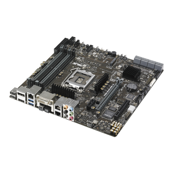
Page 17: Motherboard Overview
Before you install or remove any component, ensure that the ATX power supply is switched off or the power cord is detached from the power supply. Failure to do so may cause severe damage to the motherboard, peripherals, or components. ASUS P10S-M WS Series... -
Page 18: Motherboard Layout
1.2.2 Motherboard layout P10S-M WS/IPMI-O motherboard Chapter 1: Product Introduction... - Page 19 P10S-M WS motherboard Refer to 1.2.8 Internal connectors and 2.3.1 Rear I/O connection for more information about rear panel connectors and internal connectors. ASUS P10S-M WS Series...
-
Page 20: Layout Contents
Layout contents Connectors/Jumpers/Buttons and switches/Slots Page DDR4 sockets ATX power connectors (24-pin EATXPWR1, 8-pin EATX12V1) 1-28 Smart Ride Through (SmaRT) setting (3-pin SMART_PSU1) 1-21 Power Supply SMBus connector (5-pin PSUSMB1) 1-32 CPU, front, and rear fan connectors (4-pin CPU_FAN1; 4-pin 1-27 REAR_FAN1;... -
Page 21: Central Processing Unit (Cpu)
Contact your retailer immediately if the PnP cap is missing, or if you see any damage to the PnP cap/socket contacts/motherboard components. ASUS will shoulder the cost of repair only if the damage is shipment/ transit-related. -
Page 22: System Memory
1.2.4 System memory The motherboard comes with four (4) DDR 4 (Double Data Rate 4) Dual Inline Memory Modules (DIMM) slots. A DDR4 module is notched differently from a DDR, DDR2, or DDR3 module. DO NOT install a DDR, DDR2, or DDR3 memory module to the DDR4 slot. Recommended memory configurations Memory configurations You may install unbuffered DDR4 DIMMs into the DIMM sockets using the memory... -
Page 23: Expansion Slots
Unplug the power cord before adding or removing expansion cards. Failure to do so may cause you physical injury and damage motherboard components. Slot No. Slot Description PCIE 3.0 x1_1 slot PCIE 3.0 x16_1 slot PCIE 3.0 x8_1 slot ASUS P10S-M WS Series... - Page 24 IRQ assignments for this motherboard PCIe x1_1 shared – – – – – – – PCIe x16_1 shared – – – – – – – PCIe x8_1 shared – – – – – – – SMBUS Controller – – shared –...
-
Page 25: Onboard Leds
The BMC LED works with the ASUS ASMB8 management device and indicates its initiation status. When the PSU is plugged and the system is OFF, ASUS ASMB8 management device starts system initiation for about one (1) minute. The BMC LED blinks after system initiation finishes. - Page 26 CATT ERR LED (CATTERR1) The CATT LED indicates that the system has experienced a fatal or catastrophic error and cannot continue to operate. Message LED (MLED1) This onboard LED lights up to red when there is temperature warning or a BMC event log is generated.
- Page 27 ON, in sleep mode, or in soft-off mode. This is a reminder that you should shut down the system and unplug the power cable before removing or plugging in any motherboard component. The illustration below shows the location of the onboard LED. ASUS P10S-M WS Series 1-13...
- Page 28 Q-Code LEDs (QCODE1) The Q-Code LED design provides you with a 2-digit error code that displays the system status. Refer to the Q-Code table on the next page for details. Chapter 1: Product Introduction 1-14...
- Page 29 Recovery process started Recovery firmware image is found Recovery firmware image is loaded Reserved for future AMI progress codes F5 – F7 Recovery PPI is not available Recovery capsule is not found (continued on the next page) ASUS P10S-M WS Series 1-15...
- Page 30 Code Description Invalid recovery capsule Reserved for future AMI error codes FB – FF DXE Core is started NVRAM initialization Installation of the PCH Runtime Services CPU DXE initialization is started 63 – 67 PCI host bridge initialization System Agent DXE initialization is started System Agent DXE SMM initialization is started System Agent DXE initialization (System Agent module specific) 6B –...
- Page 31 System is waking up from the S3 sleep state System is waking up from the S4 sleep state System has transitioned into ACPI mode. Interrupt controller is in PIC mode. System has transitioned into ACPI mode. Interrupt controller is in APIC mode. ASUS P10S-M WS Series 1-17...
-
Page 32: Jumpers
1.2.7 Jumpers Clear RTC RAM (3-pin CLRTC1) This jumper allows you to clear the CMOS memory system setup parameters by erasing the CMOS Real Time Clock (RTC) RAM data. The onboard button cell battery powers the RAM data in CMOS, which include system setup information such as system passwords. - Page 33 This jumper allows you to update the BIOS ME block select. VGA controller setting (3-pin VGA_SW1) (for P10S-M WS/IPMI-O only) This jumper allows you to enable o disable the onboard VGA controller. Set to pins 1-2 to activate the VGA feature. ASUS P10S-M WS Series 1-19...
- Page 34 LAN controller setting (3-pin LAN_SW1, LAN_SW2) These jumpers allows you to enable or disable the onboard Intel I210 Gigabit LAN ® controllers. Set to pins 1-2 to activate the Gigabit LAN feature. ME firmware force recovery setting (3-pin ME_RCVR1) This jumper allows you to force Intel Management Engine (ME) boot from recovery mode when ME become corrupted.
- Page 35 This jumper allows SATA5 and SATA6 to support SATADOM which do not need external power connections. Set to pins 2-3 to activate the SATA5 and SATA6 support feature. • DOM1_PWR1 activates SATA5 support feature. • DOM2_PWR2 activates SATA6 support feature. ASUS P10S-M WS Series 1-21...
-
Page 36: Internal Connectors
1.2.8 Internal connectors Serial port connector (10-1 pin COM1) This connector is for the serial (COM) port. Connect the serial port module cable to one of these connectors, then install the module to a slot opening at the back of the system chassis. - Page 37 Mode]. Refer to section 5.1.3 Setting the RAID mode in BIOS for details. • Before creating a RAID set, refer to the manual bundled in the motherboard support DVD. VGA connector (16-1 pin VGA_HDR1) (for P10S-M WS/IPMI-O only) This connector supports the VGA High Dynamic-Range interface. ASUS P10S-M WS Series 1-23...
- Page 38 Front panel audio connector (10-1 pin AAFP1) This connector is for a chassis-mounted front panel audio I/O module that supports either HD Audio or legacy AC`97 audio standard. Connect one end of the front panel audio I/O module cable to this connector. •...
- Page 39 The plugged USB 3.0 device may run on xHCI or EHCI mode depending on the operating system’s setting. • These USB 3.0 ports support native UASP transfer standard in Windows ® Windows 8.1 and Turbo Mode when using USB 3.0 Boost feature. ® ASUS P10S-M WS Series 1-25...
- Page 40 USB 2.0 connector (10-1 pin USB78) This connector is for USB 2.0 ports. Connect the USB module cable to this connector. This USB connector complies with USB 2.0 specification that supports up to 480 Mbps connection speed. DO NOT connect a 1394 cable to the USB connectors. Doing so will damage the motherboard! The USB 2.0 module is purchased separately.
- Page 41 • These are not jumpers! DO NOT place jumper caps on the fan connectors! • All fans feature the ASUS Smart Fan technology. TPM connector (14-1 pin TPM1) This connector supports a Trusted Platform Module (TPM) system, which securely store keys, digital certificates, passwords and data. A TPM system also helps enhance network security, protect digital identities, and ensures platform integrity.
- Page 42 ATX power connectors (24-pin EATXPWR1, 8-pin EATX12V1) These connectors are for the ATX power supply plugs. The power supply plugs are designed to fit these connectors in only one orientation. Find the proper orientation and push down firmly until the connectors completely fit. •...
- Page 43 Serial General Purpose Input/Output connector (6-1 pin SGPIO1) The SGPIO 1 connector is used for the Intel Rapid Storage Technology Enterprise SGPIO interface that controls the LED pattern generation, device information, and general purpose data. ASUS P10S-M WS Series 1-29...
-
Page 44: System Panel Connector
System panel connector (20-1 pin PANEL1) This connector supports several chassis-mounted functions. System power LED (3-pin PLED) This 3-pin connector is for the system power LED. Connect the chassis power LED cable to this connector. The system power LED lights up when you turn on the system power, and blinks when the system is in sleep mode. - Page 45 Connect the Locator LED cables to these 2-pin connectors. The LEDs will light up when the Locator button is pressed. Locator Button/Switch (2-pin AUX_BMCLOCBTN) These connectors are for the locator button on the front panel. This button queries the state of the system locator. ASUS P10S-M WS Series 1-31...
- Page 46 (power supply unit) to read PSU information. Devices communicate with an SMBus host and/or other SMBus devices using the SMBus interface. This connector functions only when you enable the ASUS ASMB8. Power supply is required to meet PMBus specification and customized BMC FW may be needed.
- Page 47 ASMB8 connector (14-1 pin ASMB8) (for P10S-M WS/IPMI-O only) The ASMB8 connector on the motherboard supports an ASUS Server Management ® Board 8 Series. ASUS P10S-M WS Series 1-33...
- Page 48 Chapter 1: Product Introduction 1-34...
-
Page 49: Chapter 2: Basic Installation
The diagrams in this section are for reference only. The motherboard layout may vary with models, but the installation steps are the same for all models. Install the ASUS Q-Shield to the chassis rear I/O panel. Place the motherboard into the chassis, ensuring that its rear I/O ports are aligned to the chassis’... - Page 50 Place eight (8) screws into the holes indicated by circles to secure the motherboard to the chassis. DO NOT overtighten the screws! Doing so can damage the motherboard. Chapter 2: Basic Installation...
-
Page 51: Cpu Installation
2.1.2 CPU installation • Ensure that you install the correct CPU designed for LGA1151 socket only. DO NOT install a CPU designed for LGA1155 and LGA1156 sockets on the LGA1151 socket. • Upon purchase of the motherboard, ensure that the PnP cap is on the socket and the socket contacts are not bent. Contact your retailer immediately if the PnP cap is missing, or if you see any damage to the PnP cap/socket contacts/motherboard components. ASUS will shoulder the cost of repair only if the damage is shipment/ transit-related. • The product warranty does not cover damage to the socket contacts resulting from incorrect CPU installation/removal, or misplacement/loss/incorrect removal of the PnP cap. Load lever Retention tab CPU notches Gold triangle A l i g n m e n t... - Page 52 Load lever Load lever Retention tab Retention lock Chapter 2: Basic Installation...
-
Page 53: Cpu Heatsink And Fan Assembly Installation
2.1.3 CPU heatsink and fan assembly installation Apply the Thermal Interface Material to the CPU heatsink and CPU before you install the heatsink and fan, if necessary. To install the CPU heatsink and fan assembly ASUS P10S-M WS Series... - Page 54 To uninstall the CPU heatsink and fan assembly Chapter 2: Basic Installation...
-
Page 55: Dimm Installation
2.1.4 DIMM installation To remove a DIMM ASUS P10S-M WS Series... -
Page 56: Atx Power Connection
2.1.5 ATX Power connection Chapter 2: Basic Installation... -
Page 57: Sata Device Connection
2.1.6 SATA device connection ASUS P10S-M WS Series... -
Page 58: Front I/O Connector
2.1.7 Front I/O Connector To install USB 2.0 connector To install front panel audio connector AAFP USB 2.0 To install USB 3.0 connector USB 3.0 Chapter 2: Basic Installation 2-10... -
Page 59: Expansion Card Installation
2.1.8 Expansion Card installation To install PCIe x16 cards ASUS P10S-M WS Series 2-11... -
Page 60: Bios Update Utility
• If the light flashes for five seconds and turns into a solid light, this means that the BIOS Flashback is not operating properly. This may be caused by improper installation of the USB storage device and filename/file format error. If this scenario happens, please restart the system to turn off the light. • Updating BIOS may have risks. If the BIOS program is damaged during the process and results to the system’s failure to boot up, please contact your local ASUS Service Center. Chapter 2: Basic Installation 2-12... -
Page 61: Motherboard Rear And Audio Connection
DVI-D port Optical S/PDIF Out port Intel LAN port (LAN12)* Audio I/O ports** ® Power-on Button * and **: Refer to the tables on the next page for the LAN port LEDs and audio port definitions. The Management LAN Port (DM_LAN1) is for iKVM and only functions when you enable the ASMB8 controller. ASUS P10S-M WS Series 2-13... - Page 62 • The plugged USB 3.0 device may run on xHCI mode or EHCI mode, depending on the operating system’s setting. • USB 3.0 devices can only be used as data storage only. • We strongly recommend that you connect USB 3.0 devices to USB 3.0 ports for faster and better performance for your USB 3.0 devices. * LAN ports LED indications ACT/LINK SPEED Activity/Link LED Speed LED Status Description Status Description No link 10 Mbps connection GREEN Linked ORANGE 100 Mbps connection BLINKING Data activity GREEN...
-
Page 63: Audio I/O Connection
2.3.2 Audio I/O connection Audio I/O ports Connect to Headphone and Mic Connect to Stereo Speakers Connect to 2.1 channel Speakers ASUS P10S-M WS Series 2-15... - Page 64 Connect to 4.1 channel Speakers Connect to 5.1 channel Speakers Connect to 7.1 channel Speakers Chapter 2: Basic Installation 2-16...
-
Page 65: Starting Up For The First Time
Turning off the computer While the system is ON, press the power button for less than four seconds to put the system on sleep mode or soft-off mode, depending on the BIOS setting. Press the power switch for more than four seconds to let the system enter the soft-off mode regardless of the BIOS setting. ASUS P10S-M WS Series 2-17... - Page 66 Chapter 2: Basic Installation 2-18...
-
Page 67: Chapter 3: Bios Setup
BIOS in the future. Copy the original motherboard BIOS using the BUPDATER utility. 3.1.1 ASUS CrashFree BIOS 3 utility The ASUS CrashFree BIOS 3 is an auto recovery tool that allows you to restore the BIOS file when it fails or gets corrupted during the updating process. You can update a corrupted BIOS file using a USB flash drive that contains the updated BIOS file. -
Page 68: Asus Ezflash Utility
ASUS EzFlash Utility The ASUS EzFlash Utility feature allows you to update the BIOS using a USB flash disk without having to use a DOS-based utility. Download the latest BIOS from the ASUS website at www.asus.com before using this utility. The succeeding BIOS screens are for reference only. The actual BIOS screen displays may not be the same as shown. -
Page 69: Bupdater Utility
The BUPDATER utility allows you to update the BIOS file in DOS environment using a bootable USB flash disk drive with the updated BIOS file. Updating the BIOS file To update the BIOS file using the BUPDATER utility: Visit the ASUS website at www.asus.com and download the latest BIOS file for the motherboard. Save the BIOS file to a bootable USB flash disk drive. Download the BUPDATER utility (BUPDATER.exe) from the ASUS support website at support.asus.com to the bootable USB flash disk drive you created earlier. Boot the system in DOS mode, then at the prompt, type: BUPDATER /i[filename].CAP where [filename] is the latest or the original BIOS file on the bootable USB flash disk drive, then press <Enter>. A:\>BUPDATER /i[file name]CAP... - Page 70 The utility verifies the file, then starts updating the BIOS file. ASUS Tek. EzFlash Utility Current Platform New Platform Platform : P10S-M WS Platform : P10S-M WS Version : 0201 Version : 0206 Build date: 07/20/2015 Build date: 08/01/2015 Start Programming Flash. DO NOT SHUTDOWN THE SYSTEM!!! Write DO NOT shut down or reset the system while updating the BIOS to prevent system boot failure! The utility returns to the DOS prompt after the BIOS update process is completed.
-
Page 71: Bios Setup Program
Press <F5> and select Yes to load the BIOS default settings. • The BIOS setup screens shown in this section are for reference purposes only, and may not exactly match what you see on your screen. • Visit the ASUS website (www.asus.com) to download the latest BIOS file for this motherboard. ASUS P10S-M WS Series... -
Page 72: Bios Menu Screen
3.2.1 BIOS menu screen General help Menu items Menu bar Configuration fields Navigation keys 3.2.2 Menu bar The menu bar on top of the screen has the following main items: Main For changing the basic system configuration For changing the advanced system settings Advanced Security For changing the security settings Boot For changing the system boot configuration... -
Page 73: Menu Items
At the top right corner of the menu screen is a brief description of the selected item. 3.2.7 Configuration fields These fields show the values for the menu items. If an item is user-configurable, you can change the value of the field opposite the item. You cannot select an item that is not user- configurable. A configurable field is enclosed in brackets, and is highlighted when selected. To change the value of a field, select it and press <Enter> to display a list of options. 3.2.8 Pop-up window Select a menu item and press <Enter> to display a pop-up window with the configuration options for that item. 3.2.9 Scroll bar A scroll bar appears on the right side of a menu screen when there are items that do not fit on the screen. Press the Up/Down arrow keys or <Page Up> /<Page Down> keys to display the other items on the screen. ASUS P10S-M WS Series... -
Page 74: Main Menu
Main menu When you enter the BIOS Setup program, the Main menu screen appears. The Main menu provides you an overview of the basic system information, and allows you to set the system date and time. 3.3.1 System Date [Day xx/xx/xxxx] Allows you to set the system date. 3.3.2 System Time [xx:xx:xx] Allows you to set the system time. Chapter 3: BIOS Setup... -
Page 75: Advanced Menu
The Advanced menu items allow you to change the settings for the CPU and other system devices. Take caution when changing the settings of the Advanced menu items. Incorrect field values can cause the system to malfunction. 3.4.1 Trusted Computing Configuration Security Device Support [Enabled] Allows you to enable or disable the BIOS support for security device. Configuration options: [Disabled] [Enabled] 3.4.2 Chipset Configuration ASUS P10S-M WS Series... -
Page 76: Graphics Configuration
System Agent (SA) Configuration Allows you to set System Agent (SA) parameters. VT-d [Enabled] Allows you to enable virtualization technology function on memory control hub. Configuration options: [Disabled] [Enabled] Above 4GB MMIO BIOS assignment [Disabled] Allows you to enable or disable above 4GB MemoryMappedIO BIOS assignment. When aperture size is set to 2048 MB, this is disabled automatically. Configuration options: [Enabled] [Disabled] Graphics Configuration Allows you to select a primary display from graphical devices. - Page 77 This item is for the control of the Active State Power Management on SA side of the DMI link. Configuration options: [Disabled] [L1] PEG Port Configuration PEG 0:1:0 Enable Root Port [Auto] Allows you to enable or disable the root port. Configuration options: [Disabled] [Enabled] [Auto] ASUS P10S-M WS Series 3-11...
-
Page 78: Memory Configuration
Max Link speed [Auto] Allows you to configure PEG 0:1:0 Max Speed. Configuration options: [Auto] [Gen1] [Gen2] [Gen3] Max Link Width [Auto] Allows you to force PEG link to retrain selected value. Configuration options: [Auto] [Force X1] [Force X2] [Force X4] [Force X8] Power Down Unused Lanes [Auto] Allows you to power down unused lanes. [Disabled] No power saving. [Auto] B IOS will power down unused lanes based in the max possible link width. ASPM [Auto] Allows you to configure the PCIE ASPM. Configuration options: [Disabled] [Auto] [ASPM L0s] [ASPM L1] [ASPM L0sL1] PEG0 Max Payload size [Auto] Allows you to set the PEG0 max payload size. - Page 79 Allows you to set PCH-IO parameters. PCI Express Configuration PCI Express Clock Gating [Enabled] Allows you to enable or disable PCI Express Clock Gating for each root port. Configuration options: [Disabled] [Enabled] DMI Link ASPM Control [Enabled] Allows you to enable or disable the control of Active State Power Management on SA side of the DMI link. Configuration options: [Disabled] [Enabled] ASUS P10S-M WS Series 3-13...
-
Page 80: Usb Configuration
USB Configuration USB Precondition [Disabled] Allows you to precondition work on USB host controller and root ports for faster enumeration. Configuration options: [Enabled] [Disabled] xDCI Support [Disabled] Allows you to enable or disable xDCI (USB OTG Device). Configuration options: [Disabled] [Enabled] USB Port Disable Override [Disabled] Allows you to enable or disable the corresponding USB port from reporting a Device Connection to the controller. - Page 81 Intel Server Platform Services Intel TXT Information ASUS P10S-M WS Series 3-15...
- Page 82 PCI/PCIE Subsystem Settings PCI Latency Timer [32 PCI Bus Clocks] Allows you to set the value to be programmed into PCI Latency Timer Register. Configuration options: [32 PCI Bus Clocks] [64 PCI Bus Clocks] [96 PCI Bus Clocks] [128 PCI Bus Clocks] [160 PCI Bus Clocks] [192 PCI Bus Clocks] [224 PCI Bus Clocks] [248 PCI Bus Clocks] PERR# Generation [Disabled] Allows you to enable or disable PCI Device tp generation PERR#. Configuration options: [Disabled] [Enabled] SERR# Generation [Disabled] Allows you to enable or disable PCI Device tp generation SERR#.
-
Page 83: Platform Configuration
USB controller legacy mode is enabled. If no USB device is detected, the legacy USB support is disabled. XHCI Hand-off [Disabled] This item is set to [Disabled] by default for the EHCI (enhanced host controller interface) support by XHCI drivers in operating systems. [Enabled] Support XHCI by BIOS for operating systems without XHCI support. [Disabled] Support XHCI by XHCI drivers for operating systems with XHCI support. ASUS P10S-M WS Series 3-17... - Page 84 USB Mass Storage Driver Support [Enabled] Allows you to enable or disable the USB Mass Storage driver support. Configuration options: [Disabled] [Enabled] Port 60/64 Emulation [Enabled] This allows you to enable the I/O port 60h/64h emulation support. This should be enabled for the complete USB keyboard legacy support for non-USB aware OSes. Configuration options: [Disabled] [Enabled] USB hardware delays and time-outs USB transfer time-out [20 sec]...
- Page 85 Allows you to select the Intel LAN ROM type. Configuration options: [Disabled] [PXE] [iSCSI] Intel LAN2 Enable [Enabled] Allows you to enable or disable the Intel LAN. Configuration options: [Disabled] [Enabled] Intel LAN2 ROM Type [Disabled] Allows you to select the Intel LAN ROM type. Configuration options: [Disabled] [PXE] [iSCSI] Super IO Configuration ASUS P10S-M WS Series 3-19...
- Page 86 Serial Port 1 Configuration Allows you to set the parameters of Serial Port 1. Serial Port [Enabled] Allows you to enable or disable Serial Port. Configuration options: [Disabled] [Enabled] The following item appears only when you set Serial Port to [Enabled]. Change Settings [Auto] Allows you to choose the setting for Super IO device.
- Page 87 A parity bit can be sent with the data bits to detect some transmission errors. [Mark] and [Space] parity do not allow for error detection. [None] None. [Even] parity bit is 0 if the num of 1’s in the data bits is even. [Odd] parity bit is 0 if num of 1’s in the data bits is odd. [Mark] parity bit is always 1. [Space] parity bit is always 0. Stop Bits [1] Stop bits indicate the end of a serial data packet. (A start bit indicates the beginning.) The standard setting is 1 stop bit. Communication with slow devices may require more than 1 stop bit. Configuration options: [1] [2] ASUS P10S-M WS Series 3-21...
- Page 88 Flow Control [Hardware RTS/CTS] Flow control can prevent data loss from buffer overflow. When sending data, if the receiving buffers are full, a “stop” signal can be sent to stop the data flow. Once the buffers are empty, a “start” signal can be sent to re-start the flow. Hardware flow control uses two wires to send start/stop signals. Configuration options: [None] [Hardware RTS/CTS] VT-UTF8 Combo Key Support [Enabled] Allows you to enable the VT-UTF8 Combo Key Support for ANSI/VT100 terminals. Configuration options: [Disabled] [Enabled] Recorder Mode [Disabled] With this mode enabled only text will be sent. This is to capture Terminal data. Configuration options: [Disabled] [Enabled] Legacy OS Redirection Resolution [80x24] Allows you to set the number of rows and columns supported on the Legacy OS.
- Page 89 This option may be not be effective with some OS. ACPI Sleep State [S3 (Suspend to RAM)] Allows you to select the highest ACPI sleep state the system will enter when the SUSPEND button is pressed. Configuration options: [Suspend Disabled] [S3 (Suspend to RAM)] ASUS P10S-M WS Series 3-23...
-
Page 90: Smart Settings
Allows you to configure the Advance Power Management (APM) settings. Restore AC Power Loss [Last State] When set to [Power Off], the system goes into off state after an AC power loss. When set to [Power On], the system will reboot after an AC power loss. When set to [Last State], the system goes into either off or on state, whatever the system state was before the AC power loss. Configuration options: [Power Off] [Power On] [Last State] Power On By PCIE [Disabled] [Disabled] Disables the PCIE devices to generate a wake event. [Enabled] Enables the PCIE devices to generate a wake event. Power On By Ring [Disabled] [Disabled] Disables the Ring devices to generate a wake event. -
Page 91: Cpu Configuration
Some items may not appear if your CPU does not support the related functions. Navigate to the second page of the screen to see the rest of items in this menu by pressing the Up or Down arrow keys. To quickly go to the last item of the second page, press the Page Down button. Press the Page Up button to go back to the first item in the first page. ASUS P10S-M WS Series 3-25... - Page 92 Hyper-threading [Enabled] This item allows a hyper-threading processor to appear as two logical processors, allowing the operating system to schedule two threads or processors simultaneously. Configuration options: [Disabled] [Enabled] Active Processor Cores [All] Allows you to select the number of CPU cores to activate in each processor package. Configuration options: [All] [1] [2] [3] Intel Virtualization Technology [Enabled] When set to [Enabled], a VMM can utilize the additional hardware capabilities provided by Vanderpool Technology. Configuration options: [Disabled] [Enabled] Hardware Prefetcher [Enabled] Allows you to enable or disable the MLC streamer prefetcher.
- Page 93 Package C state undemotion [Disabled] Allows you to enable or disable the Package C state undemotion. Configuration options: [Disabled] [Enabled] CState Pre-Wake [Enabled] Allows you to enable or disable the CState Pre-Wake. Selecting [Disabled] will set bit 30 of POWER_CTL MSR(0x1FC) to 1 to disable the CState Pre-Wake. Configuration options: [Disabled] [Enabled] Package C State limit [C8] Allows you set the Package C State limit. Configuration options: [C0/C1] [C2] [C3] C6] [C7] [C7s] [C8] [AUTO] CFG lock [Enabled] Allows you to configure MSR 0xE2[15], CFG lock bit. Configuration options: [Disabled] [Enabled] Intel TXT(LT) Support [Disabled] Allows you to enable or disable the Intel(R) TXT(LT) support. Configuration options: [Disabled] [Enabled] ASUS P10S-M WS Series 3-27...
-
Page 94: Sata Configuration
3.4.5 SATA Configuration SATA Controller(s) [Enabled] Allows you to enable or disable the SATA Device. Configuration options: [Enabled] [Disabled] The following items appear only when you set SATA Controller(s) to [Enabled]. SATA Mode Selection [AHCI] This item allows you to set the SATA configuration. [AHCI] S et to [AHCI] when you want the SATA hard disk drives to use the AHCI (Advanced Host Controller Interface). The AHCI allows the onboard storage driver to enable advanced Serial ATA features that increases storage performance on random workloads by allowing the drive to internally optimize the order of commands. -
Page 95: Software Feature Mask Configuration
Allows you to enable or disable the Intel Rapid Recovery Technology. Configuration options: [Disabled] [Enabled] OROM UI and BANNER [Enabled] [Disabled] N o OROM banner or information will be displayed if all disks and RAID volumes are Normal. [Enabled] OROM UI is shown. HDD Unlock [Enabled] Selecting [Enabled] will indicate that the HDD password unlock in the OS is enabled. Configuration options: [Disabled] [Enabled] LED Locate [Enabled] Selecting [Enabled] will indicate that the LED/SGPIO hardware is attached and ping to locate feature is enabled on the OS. Configuration options: [Disabled] [Enabled] ASUS P10S-M WS Series 3-29... - Page 96 IRRT Only on eSATA [Enabled] [Disabled] Any RAID volume can span internal and eSATA drives. [Enabled] Only IRRT volumes can span internal and eSATA drives. Smart Response Technology [Enabled] Allows you to enable or disable the Smart Response Technology. Configuration options: [Disabled] [Enabled] OROM UI Normal Delay [4 sec] Allows you to select the delay time of the OROM UI Splash Screen in a normal status. Configuration options: [2 sec] [4 sec] [6 sec] [8 sec] RST Force Form [Disabled] Allows you to enable or disable Form for Intel Rapid Storage Technology.
-
Page 97: Network Stack Configuration
Enables or disables the Ipv6 PXE Boot Support. If disabled, Ipv6 PXE boot option will not be created. Configuration options: [Disable] [Enable] PXE boot wait time [0] Set the wait time to press ESC key to abort the PXE boot. Use the <+> or <-> to adjust the value. The values range from 0 to 5. Media detect count [1] Set the number of times presence of media will be checked. Use the <+> or <-> to adjust the value. The values range from 1 to 50. ASUS P10S-M WS Series 3-31... -
Page 98: Csm Configuration
3.4.7 CSM Configuration CSM Support [Enabled] This option allows you to enable or disable CSM Support. Configuration options: [Disabled] [Enabled] The following items appear only when you set the CSM Support to [Enabled]. GateA20 Active [Upon Request] This allows you to set the GA20 option. [Upon Request] GA20 can be disabled using BIOS services. -
Page 99: Iscsi Configuration
Other PCI devices [Legacy] This item determines the OpROM execution policy for devices other than Network, Storage, or Video. Configuration options: [UEFI ] [Legacy] 3.4.8 iSCSI Configuration Allows you to configure the iSCSi parameters. Security Menu This menu allows a new password to be created or a current password to be changed. The menu also enables or disables the Secure Boot state and lets the user configure the System Mode state. ASUS P10S-M WS Series 3-33... -
Page 100: Administrator Password
Administrator Password To set an administrator password: Select the Administrator Password item and press <Enter>. From the Create New Password box, key in a password, then press <Enter>. Confirm the password when prompted. To change an administrator password: Select the Administrator Password item and press <Enter>. From the Enter Current Password box, key in the current password, then press <Enter>. From the Create New Password box, key in a new password, then press <Enter>. Confirm the password when prompted. To clear the administrator password, follow the same steps as in changing an administrator password, but press <Enter> when prompted to create/confirm the password. -
Page 101: Secure Boot Menu
This item will ask you if you want to Install Factory Default secure variables. Select Yes if you want to load the default secure variables, otherwise select No. This option will change to Delete all Secure Boot variables once default keys are loaded, selecting this will then ask to delete all variables and reset the Platform to Setup Mode. The following item is only available when default secure variables are loaded. ASUS P10S-M WS Series 3-35... -
Page 102: Boot Menu
Save all Secure Boot variables Save the secure boot variables to a selected file system. Platform Key (PK) Configuration options: [Set New Key] [Delete Key] Key Exchange Keys / Authorized Signatures / Forbidden Signatures Configuration options: [Set New Key] [Delete Key] [Append Key] Authorized TimeStamps Configuration options: [Set New Key] [Append Key] Boot Menu The Boot menu items allow you to change the system boot options. Bootup NumLock State [On] Allows you to select the power-on state for the NumLock. -
Page 103: Monitor Menu
SATA devices. Monitor Menu The Monitor menu displays the system temperature/power status, and allows you to change the fan settings. Fan Speed Control [Generic Mode] Allows you to set the fan speed. Configuration options: [Generic Mode] [High Speed Mode] [Full Speed Mode] ASUS P10S-M WS Series 3-37... -
Page 104: Tool Menu
The Tool menu items allow you to configure options for special functions. Select an item then press <Enter> to display the submenu. Start EzFlash Allows you to run ASUS EZ Flash BIOS ROM Utility when you press <Enter>. Refer to the ASUS EzFlash Utility section for details. Save & Exit menu The Exit menu items allow you to save or discard your changes to the BIOS items. -
Page 105: Server Mgmt Menu (P10S-M Ws/Ipmi-O Only)
This item allows you to start a BIOS timer which can only be shut off by Management Software after the OS loads. Configuration options: [Enabled] [Disabled] The following items is configurable only when the OS Watchdog Timer is set to [Enabled]. OS Wtd Timer Timeout [10 minutes] Allows you to configure the length for the OS Boot Watchdog Timer. Configuration options: [5 minutes] [10 minutes] [15 minutes] [20 minutes] OS Wtd Timer Policy [Reset] This item allows you to configure how the system should respond if the OS Boot Watchdog Timer expires. Configuration options: [Do Nothing] [Reset] [Power Down] [Power Cycle] ASUS P10S-M WS Series 3-39... -
Page 106: System Event Log
System Event Log Allows you to change the System Event Log configuration. All values changed here do not take effect until computer is restarted. Erase SEL [No] Allows you to choose options for erasing SEL. Configuration options: [No] [Yes, On next reset] [Yes, On every reset] When SEL is Full [Do Nothing] Allows you to choose options for reactions to a full SEL. Configuration options: [Do Nothing] [Erase Immediately] Log EFI Status Codes [Error code] Disable the logging of EFI Status Codes, or log only error code, or only progress code, or both. -
Page 107: Bmc Network Configuration
BMC network configuration The sub-items in this configuration allow you to configure the BMC network parameters. DM_LAN1 / Shared LAN Config Address source [Previous State] This item allows you to configure LAN channel parameters statistically or dynamically (by BIOS or BMC). Previous State option will not modify any BMC network parameters during BIOS phase. Configuration options: [Previous State] [Static] [DynamicBmcDhcp] View System Event Log This item allows you to view the System Event Log Records. ASUS P10S-M WS Series 3-41... -
Page 108: Ipv6 Bmc Network Configuration
IPv6 BMC Network Configuration This item allows you to configure the parameter settings of IPv6 BMC network. IPv6 Display Full Field [Enable] Displays the Full or Brief IPv6 Field. Configuration options: [Disable] [Enable] IPv6 Display Full Formula [Enable] Displays the Full or Brief IPv6 Formula. Configuration options: [Disable] [Enable] IPv6 Display Letter Case [Upper Case] Displays the uppercase or lowercase letters of the alphabet. Configuration options: [Lower Case] [Upper Case] IPv6 BMC DM_LAN1 / Shared LAN IPv6 BMC LAN IP Address source [Previous State]... -
Page 109: Event Logs Menu
Change this to enable or disable all features of Smbios Event Logging during boot. Configuration options: [Disabled] [Enabled] • The following items appears only when you set Smbios Event Log to [Enabled]. • All values changed here do not take effect until computer is restarted. Erasing Settings Erase Event Log [No] Choose options for erasing Smbios Event Log. Erasing is done prior to any logging activation during reset. Configuration options: [No] [Yes, Next reset] [Yes, Every reset] ASUS P10S-M WS Series 3-43... - Page 110 When Log is Full [Do Nothing] Allows you to choose options for reactions to a full Smbios Event Log. Configuration options: [Do Nothing] [Erase Immediately] Smbios Event Log Standard Settings Log System Boot Event [Disabled] Allows you to enable or disable logging of System boot event. Configuration options: [Enabled] [Disabled] MECI [1] Also known as Multiple Event Count Increment, and allows you to set the value for the...
-
Page 111: Chapter 4: Software Support
Server 2008 OS ® Boot the computer using the Windows Server 2008 OS installation disc. Follow the ® screen instructions to start installing Windows Server 2008. ® When prompted to choose a type of installation, click Custom (advanced). ASUS P10S-M WS Series... - Page 112 Click Load Driver. A message appears reminding you to insert the installation media containing the driver of the RAID controller driver (the installation media can be a CD, DVD, or USB flash drive). • If you have only one optical drive installed in your system, eject the Windows OS installation disc and replace with the motherboard Support DVD into the optical drive.
- Page 113 When the system finishes loading the RAID driver, • Replace the motherboard Support DVD with the Windows Server installation disc. • Remove the USB flash drive. Select the drive to install Windows and click Next. Follow succeeding screen instructions to continue. ASUS P10S-M WS Series...
-
Page 114: Management Applications And Utilities Installation
• The contents of the support DVD are subject to change at any time without notice. Visit the ASUS website (www.asus.com) for the latest updates on software and utilities. ®... -
Page 115: Drivers Menu Tab
The Drivers Menu shows the available device drivers if the system detects installed devices. Install the necessary drivers to activate the devices. 4.3.2 Utilities menu tab The Utilities menu displays the software applications and utilities that the motherboard supports. ASUS P10S-M WS Series... -
Page 116: Manual Menu
4.3.3 Manual menu The Manual menu provides the link to the P10S-M WS Series user guide. You need an internet browser installed in your OS to view the User Guide. 4.3.4 Contact information menu The Contact menu displays the ASUS contact information, e-mail addresses, and useful links if you need more information or technical support for your motherboard. -
Page 117: Installing The Intel ® Chipset Device Software Driver
ASSETUP.EXE from the BIN folder. Double-click the ASSETUP.EXE to run the support DVD. Click Intel Chipset Device Software from the Drivers menu to start the installation. ® The Intel(R) Chipset Device Software window appears. Click Next to start installation. ASUS P10S-M WS Series... - Page 118 Select Yes to accept the terms of the License Agreement and continue the process. Read the Readme File Information and press Next to continue the installation. Toggle Yes, I want to restart the computer now and click Finish to complete the setup process.
-
Page 119: Installing The Intel I210 Gigabit Adapters Driver
ASSETUP.EXE from the BIN folder. Double-click the ASSETUP.EXE to run the support DVD. Click Intel I210 Gigabit Adapters Drivers in the Drivers menu of the main screen to ® start the installation. Click Install Drivers and Software option to begin installation. ASUS P10S-M WS Series... - Page 120 Click Next when the Intel(R) Network Connections–InstallShield Wizard window appears. Tick I accept the terms in the license agreement and click Next to continue. From the Setup Options window, click Next to start the installation. By default, Intel(R) PROSet for Windows Device Manager and Windows PowerShell Module are ticked.
- Page 121 Click Install to start the installation. When the installation is done, press Finish to complete the installation. ASUS P10S-M WS Series 4-11...
- Page 122 Chapter 4: Software Support 4-12...
-
Page 123: Chapter 5: Raid Support
If you want to boot the system from a hard disk drive included in a created RAID set, copy first the RAID driver from the support DVD to a floppy disk before you install an operating system to the selected hard disk drive. ASUS P10S-M WS Series... -
Page 124: Installing Hard Disk Drives
5.1.2 Installing hard disk drives The motherboard supports Serial ATA for RAID set configuration. For optimal performance, install identical drives of the same model and capacity when creating a disk array. To install the SATA hard disks for RAID configuration: Install the SATA hard disks into the drive bays following the instructions in the system user guide. -
Page 125: Intel ® Rapid Storage Technology Enterprise Sata Option Rom Utility
The navigation keys at the bottom of the screen allow you to move through the menus and select the menu options. The RAID BIOS setup screens shown in this section are for reference only and may not exactly match the items on your screen. ASUS P10S-M WS Series... -
Page 126: Creating A Raid Set
5.2.1 Creating a RAID set To create a RAID set: From the utility main menu, select 1. Create RAID Volume and press <Enter>. Key in a name for the RAID set and press <Enter>. Intel(R) Rapid Storage Technology enterprise - SATA Option ROM - 3.6.0.1023 Copyright(C) 2003-12 Intel Corporation. - Page 127 From the following warning message, press <Y> to create the RAID volume and return to the main menu, or press <N> to go back to the CREATE VOLUME menu. WARNING: ALL DATA ON SELECTED DISKS WILL BE LOST. Are you sure you want to create this volume? (Y/N): ASUS P10S-M WS Series...
-
Page 128: Deleting A Raid Set
5.2.2 Deleting a RAID set Take caution when deleting a RAID set. You will lose all data on the hard disk drives when you delete a RAID set. To delete a RAID set: From the utility main menu, select 2. Delete RAID Volume and press <Enter>. From the Delete Volume Menu, press the up/down arrow keys to select the RAID set you want to delete then press <Del>. -
Page 129: Resetting Disks To Non-Raid
ST3300656SS 37VN00009846RAJ1 279.3GB Member Disk Select the disks that should be reset. ]-Previous/Next [SPACE]-Selects [ENTER]-Selection Complete Press <Y> in the confirmation window to reset the drive(s) or press <N> to return to the utility main menu. ASUS P10S-M WS Series... -
Page 130: Exiting The Intel ® Rapid Storage Technology Enterprise
5.2.4 Exiting the Intel Rapid Storage Technology enterprise ® SATA Option ROM utility To exit the utility: From the utility main menu, select 4. Exit then press <Enter>. Press <Y> to exit or press <N> to return to the utility main menu. CONFIRM EXIT Are you sure you want to exit? (Y/N): 5.2.5... - Page 131 Remove the failed SATA hard disk and install a new SATA hard disk of the same specification into the same SATA Port. Select a destination disk with the same size as the original hard disk. Reboot the system then follow the steps in section Rebuilding the RAID with other non-RAID disk. ASUS P10S-M WS Series...
-
Page 132: Setting The Boot Array In The Bios Setup Utility
5.2.6 Setting the Boot array in the BIOS Setup Utility You can set the boot priority sequence in the BIOS for your RAID arrays when creating multi- RAID using the Intel Rapid Storage Technology enterprise SATA Option ROM utility. ® To set the boot array in the BIOS: Set at least one of the arrays bootable to boot from the hard disk. -
Page 133: Intel ® Rapid Storage Technology Enterprise (Windows)
Your storage system is configured for data protection, increased performance and optimal data storage capacity. You can create additional volumes to further optimize your storage system. You can click Rescan to re-scan any attached hard disks. ASUS P10S-M WS Series 5-11... -
Page 134: Creating A Raid Set
5.3.1 Creating a RAID set To create a RAID set: From the utility main menu, select Create Volume then select volume type and click Next. Key in a name for the RAID set, then select the array disks. Select the Volume Size tab then drag the bar to set the volume size. Click Next. - Page 135 You still need to partition your new volume using Windows Disk Management before adding any data. The created RAID set is displayed in the Volumes list. If you wish to change the settings, go to Volume Properties. ASUS P10S-M WS Series 5-13...
-
Page 136: Changing A Volume Type
5.3.2 Changing a Volume Type To change the volume type in Volume Properties: Click the SATA array items you want to change in Volumes field. From the Volume Properties field, select Type: RAID 1 Change type. You can also change the Name, Select the new volume type, and Select additional disks to include in the new volume if needed. -
Page 137: Deleting A Volume
From the Volumes field in the utility main menu, select the volume that you want to delete. From the Volume Properties field, select Delete volume. Click Yes to delete the volume and return to the utility main menu, or click No to return to the main menu. ASUS P10S-M WS Series 5-15... -
Page 138: Preferences
5.3.4 Preferences System Preferences Allow you to set to show the notification area icon and show system information, warning, or errors here. E-mail Preferences Allow you to set to sent e-mail of the following events: • Storage system information • Storage system warnings •... -
Page 139: Appendices
Appendices Appendix P10S-M WS/IPMI-O block diagram ASUS P10S-M WS Series... -
Page 140: P10S-M Ws Block Diagram
P10S-M WS block diagram Appendix... -
Page 141: Notices
Consult the dealer or an experienced radio/TV technician for help. The use of shielded cables for connection of the monitor to the graphics card is required to assure compliance with FCC regulations. Changes or modifications to this unit not expressly approved by the party responsible for compliance could void the user’s authority to operate this equipment. ASUS P10S-M WS Series... -
Page 142: Canadian Department Of Communications Statement
IC: Canadian Compliance Statement Complies with the Canadian ICES-003 Class B specifications. This device complies with RSS 210 of Industry Canada. This Class B device meets all the requirements of the Canadian interference-causing equipment regulations. This device complies with Industry Canada license exempt RSS standard(s). Operation is subject to the following two conditions: (1) this device may not cause interference, and (2) this device must accept any interference, including interference that may cause undesired operation of the device. - Page 143 ASUS Recycling/Takeback Services ASUS recycling and takeback programs come from our commitment to the highest standards for protecting our environment. We believe in providing solutions for you to be able to responsibly recycle our products, batteries, other components as well as the packaging materials.
- Page 144 Slovenščina AsusTek Inc. tukaj izjavlja, da je ta naprava skladna s di conformità CE. temeljnimi zahtevami in drugimi relevantnimi določili direktiv CE. Za več Русский Компания ASUS заявляет, что это устройство соответствует informacij glejte Izjavo CE o skladnosti. основным требованиям и другим соответствующим условиям...
-
Page 145: Asus Contact Information
Support fax +1-812-284-0883 Telephone +1-812-282-2787 Online support http://www.service.asus.com/ ASUS TECHNOLOGY HOLLAND B.V. Address Fultonbaan 12, 3439 NE, Nieuwegein, The Netherlands +31306021594 Web site http://www.asus.com/be-nl/ Online contact http://eu-rma.asus.com/sales Technical Support Telephone +31306004222 Support Fax +31306021594 Online support http://www.asus.com/be-nl/support/ ASUS P10S-M WS Series... - Page 146 Appendix...
Need help?
Do you have a question about the P10S-M WS Series and is the answer not in the manual?
Questions and answers