Table of Contents
Advertisement
Quick Links
Advertisement
Table of Contents

Related Manuals for Asus P10S-E/4L


Summary of Contents for Asus P10S-E/4L
- Page 1 P10S-E/4L...
- Page 2 Product warranty or service will not be extended if: (1) the product is repaired, modified or altered, unless such repair, modification of alteration is authorized in writing by ASUS; or (2) the serial number of the product is defaced or missing.
-
Page 3: Table Of Contents
Package contents ..................1-2 Serial number label ..................1-3 Special features..................1-3 1.4.1 Product highlights................ 1-3 1.4.2 Innovative ASUS features ............1-5 Chapter 2: Hardware Information Before you proceed ................... 2-2 Motherboard overview ................2-3 2.2.1 Placement direction..............2-3 2.2.2 Screw holes................. - Page 4 3.2.2 Using the dual function power switch .......... 3-3 Chapter 4: BIOS Setup Managing and updating your BIOS ............4-2 4.1.1 ASUS CrashFree BIOS 3 utility........... 4-2 4.1.2 ASUS EzFlash Utility..............4-3 4.1.3 BUPDATER utility ............... 4-4 BIOS setup program .................. 4-6 4.2.1...
- Page 5 Contents Main menu ....................4-9 4.3.1 System Date................4-9 4.3.2 System Time ................4-9 Advanced menu ..................4-10 4.4.1 Trusted Computing..............4-11 4.4.2 Chipset Configuration..............4-11 4.4.3 Platform Configuration .............. 4-21 4.4.4 CPU Configuration ..............4-31 4.4.5 SATA Configuration ..............4-35 4.4.6 Network Stack Configuration ............
- Page 6 Chipset device Software driver ..... 6-9 ® Installing the Intel I210 Gigabit Adapters driver ........6-12 Installing the VGA driver ................. 6-15 Appendix P10S-E/4L block diagram ................. A-2 Simplified EU Declaration of Conformity .............. A-3 ASUS contact information ..................A-4...
-
Page 7: Notices
Notices Federal Communications Commission Statement This device complies with Part 15 of the FCC Rules. Operation is subject to the following two conditions: • This device may not cause harmful interference, and • This device must accept any interference received including interference that may cause undesired operation. - Page 8 (2) l’utilisateur de l’appareil doit accepter tout brouillage radioélectrique subi, même si le brouillage est susceptible d’en compromettre le fonctionnement. CAN ICES-3(B)/NMB-3(B) REACH Complying with the REACH (Registration, Evaluation, Authorization, and Restriction of Chemicals) regulatory framework, we publish the chemical substances in our products at ASUS REACH website at http://csr.asus.com/english/REACH.htm. viii...
-
Page 9: Safety Information
Safety information Electrical safety • To prevent electrical shock hazard, disconnect the power cable from the electrical outlet before relocating the system. • When adding or removing devices to or from the system, ensure that the power cables for the devices are unplugged before the signal cables are connected. If possible, disconnect all power cables from the existing system before you add a device. - Page 10 If you require assistance please call ASUS Customer Service 1300 2787 88 or visit us at https://www.asus.com/support/.
- Page 11 Conventions used in this guide To ensure that you perform certain tasks properly, take note of the following symbols used throughout this manual. DANGER/WARNING: Information to prevent injury to yourself when trying to complete a task. CAUTION: Information to prevent damage to the components when trying to complete a task IMPORTANT: Instructions that you MUST follow to complete a task.
-
Page 12: Specifications Summary
Optional Kits: - ASUS PIKE II 3008-8i 8-port SAS 12G RAID card SAS Controller - ASUS PIKE II 3108-8i 8-port SAS 12G HW RAID card * Refer to www.asus.com for the complete list of supported CPUs. (continued on the next page) - Page 13 ® 4 x Intel I210 + 1 x Mgmt LAN Networking Graphic Aspeed AST2400 32MB TPM Header 24-pin ATX power connector + PSU Connector 8-pin ATX 12V power connector Management Onboard header for optional management card Header 1 x USB 3.0 pin header (up to 2 devices) USB Connector/ 2 x USB 2.0 pin header (up to 4 devices) Header...
-
Page 15: Chapter 1: Product Introduction
Chapter 1: Product Introduction Chapter 1: Product Introduction... -
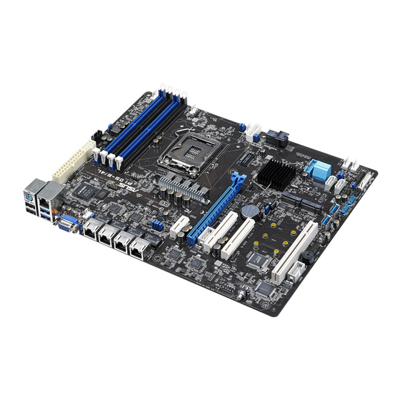
Page 16: Welcome
P10S-E/4L motherboard! The motherboard delivers a host of new features and latest technologies, making it another standout in the long line of ASUS quality motherboards! Before you start installing the motherboard and hardware devices on it, check the items in your package with the list below. -
Page 17: Serial Number Label
Serial number label Before requesting support from the ASUS Technical Support team, you must take note of the motherboard's serial number containing 12 characters xxS2xxxxxxxx shown as the figure below. With the correct serial number of the product, ASUS Technical Support team members can then offer a quicker and satisfying solution to your problems. - Page 18 PCI Express 3.0 PCI Express 3.0 (PCIe 3.0) is the PCI Express bus standard that provides twice the performance and speed of PCIe 2.0. It provides an optimal graphics performance, unprecedented data speed, and seamless transition with its complete backward compatibility to PCIe 1.0/2.0 devices.
-
Page 19: Innovative Asus Features
1.4.2 Innovative ASUS features ASUS Fan Speed technology The ASUS Fan Speed technology smartly adjusts the fan speeds according to the system loading to ensure quiet, cool, and efficient operation. ASUS MIO Audio card The ASUS MIO audio card is a discrete 8-channel high definition audio (High Definition Audio previously codenamed Azalia) CODEC that enables the clearest high quality audio output. - Page 20 Chapter 1: Product Introduction...
-
Page 21: Chapter 2: Hardware Information
Chapter 2: Hardware Information Chapter 2: Hardware Information... -
Page 22: Before You Proceed
Before you proceed Take note of the following precautions before you install motherboard components or change any motherboard settings. • Unplug the power cord from the wall socket before touching any component. • Use a grounded wrist strap or touch a safely grounded object or a metal object, such as the power supply case, before handling components to avoid damaging them due to static electricity. • Hold components by the edges to avoid touching the ICs on them. • Whenever you uninstall any component, place it on a grounded antistatic pad or in the bag that came with the component. • Before you install or remove any component, ensure that the power supply is switched off or the power cord is detached from the power supply. Failure to do so may cause severe damage to the motherboard, peripherals, and/or components. -
Page 23: Motherboard Overview
Motherboard overview Before you install the motherboard, study the configuration of your chassis to ensure that the motherboard fits into it. To optimize the motherboard features, we highly recommend that you install it in an ATX 1.1 compliant chassis. Ensure to unplug the chassis power cord before installing or removing the motherboard. Failure to do so can cause you physical injury and damage motherboard components! 2.2.1 Placement direction When installing the motherboard, ensure that you place it into the chassis in the correct orientation. The edge with external ports goes to the rear part of the chassis as indicated in the image below. ASUS P10S-E/4L... -
Page 24: Screw Holes
2.2.2 Screw holes Place nine (9) screws into the holes indicated by circles to secure the motherboard to the chassis. Place this side towards the rear of the chassis DO NOT overtighten the screws! Doing so can damage the motherboard. Chapter 2: Hardware Information... -
Page 25: Motherboard Layout
2.2.3 Motherboard layout ASUS P10S-E/4L... -
Page 26: Layout Contents
2.2.4 Layout contents Slots/Sockets Page CPU sockets DDR4 sockets 2-14 PCI Express x16 / PCI Express x8 /PCI Express x8 / PCI slot 2-17 Onboard LEDs Page Standby Power LED (SBPWR1) 2-21 Baseboard Management Controller LED (BMCLED1) 2-21 CPU Warning LED (ERRCPU1) 2-22 Message LED (MLED1) 2-22 CATT ERR LED (CATTERR1) 2-23 Jumpers Page Clear RTC RAM (3-pin CLRTC) 2-24 VGA controller setting (3-pin VGA_SW1) 2-25 LAN controller setting (3-pin LAN_SW1-4) 2-25 ME firmware force recovery setting (3-pin ME_RCVR1) 2-26 PCH_MFG1 setting (3-pin PCH_MFG1) 2-26 SATA DOM power setting (3-pin DOM_PWR1-2) 2-27 Smart Ride Through setting (3-pin SMART_PSU1) 2-27 Rear panel connectors Page PS/2 keyboard/mouse port 2-28... - Page 27 2-33 (4-pin FRNT_FAN1-4, REAR_FAN1, CPU_FAN1) Serial General Purpose Input/Output connector (6-1 pin SGPIO1) 2-34 Serial port connectors (10-1 pin COM1/COM2) 2-34 Power Supply SMBus connector (5-pin PSUSMB1) 2-35 10. Trusted Platform Module connector (14-1 pin TPM) 2-35 11. SATA DOM power connector (4-pin PWR3) 2-36 12. LAN34_LED connector (5-1 pin LAN34_LED1) 2-37 VGA connector (16-1 pin VGA_HDR1) 2-37 14. ATX power connectors (24-pin EATXPWR1, 8-pin EATX12V1) 2-38 System panel connector (20-1 pin PANEL1) 2-39 16. Auxiliary panel connector (20-2 pin AUX_PANEL1) 2-40 17. M.2 (NGFF) card connector (NGFF1 & NGFF2) 2-41 18. S ystem Management Bus (SMBUS) connector 2-41 (5-1 pin SMBUS1) 19. Chassis intrusion connector (2-pin INTRUSION1) 2-42 ASUS P10S-E/4L...
-
Page 28: Central Processing Unit (Cpu)
Central Processing Unit (CPU) ® ® The motherboard comes with a surface mount LGA1151 socket designed for the Intel Xeon ® E3-1200 v5 and Intel Core™ i3 processor. • Upon purchase of the motherboard, ensure that the PnP cap is on the socket and the socket contacts are not bent. Contact your retailer immediately if the PnP cap is missing, or if you see any damage to the PnP cap/socket contacts/motherboard components. ASUS will shoulder the cost of repair only if the damage is shipment/ transit-related. • The product warranty does not cover damage to the socket contacts resulting from incorrect CPU installation/removal, or misplacement/loss/incorrect removal of the PnP cap. 2.3.1 Installing the CPU To install the CPU: Locate the CPU socket on the motherboard. Before installing the CPU, ensure that the socket box is facing toward you and the load lever is on your right. Chapter 2: Hardware Information... - Page 29 Do not remove the PnP cap yet from the CPU socket. Doing so may bend the pins of the socket. Retention tab Lift the load lever until the load plate is completely lifted. Load plate Position the CPU above the socket, ensuring that the gold triangle mark is on the bottom-left corner of the socket, then fit the CPU notches to the socket's CPU notches alignment keys. The CPU fits in only one orientation. DO NOT force the CPU into the socket to prevent bending the pins on Gold Alignment triangle the socket and damaging the CPU. mark Alignment ASUS P10S-E/4L...
- Page 30 Close the load plate (A), ensuring that the front edge of the load plate slides under the retention lock (B) then push Load lever down the load lever (C). Retention lock Insert the load lever under the retention tab to remove the PnP cap from the CPU socket. Load lever Retention tab Apply some Thermal Interface Material to the exposed area of the CPU that the heatsink will be in contact with, ensuring that it is evenly spread in a thin layer. Some heatsinks come with pre-applied Thermal Interface Material. If so, skip this step. The Thermal Interface Material is toxic and inedible. DO NOT eat it. If it gets into your eyes or touches your skin, wash it off immediately and seek professional medical help. 2-10 Chapter 2: Hardware Information...
-
Page 31: Installing The Cpu Heatsink
If you purchased a separate CPU heatsink and fan assembly, ensure that the Thermal Interface Material is properly applied to the CPU heatsink or CPU before you install the heatsink and fan assembly. Ensure that you have installed the motherboard to the chassis before you install the CPU fan and heatsink assembly. To install the CPU heatsink and fan: Place the heatsink on top of the installed CPU, making sure that the four fasteners match the holes on the motherboard. Push down two fasteners at a time in a diagonal sequence to secure the heatsink and fan assembly in place. Orient the heatsink and fan assembly such that the CPU fan cable is closest to the CPU fan connector. ASUS P10S-E/4L 2-11... -
Page 32: Uninstalling The Cpu Heatsink And Fan
Connect the CPU fan cable to the connector on the motherboard labeled CPU_FAN1. DO NOT forget to connect the CPU fan connector! Hardware monitoring errors can occur if you fail to plug this connector. 2.3.3 Uninstalling the CPU heatsink and fan To uninstall the CPU heatsink and fan: Disconnect the CPU fan cable from the connector on the motherboard. Rotate each fastener counterclockwise. Pull up two fasteners at a time in a diagonal sequence to disengage the heatsink and fan assembly from the motherboard. Carefully remove the heatsink and fan assembly from the motherboard. 2-12 Chapter 2: Hardware Information... -
Page 33: Installing The Cpu Heatsink In Rack
® The Intel LGA1151 processor requires a specially designed heatsink to ensure optimum thermal condition and performance. • Ensure that you use qualified heatsink assembly only. • Ensure that you have applied the thermal interface material to the top of the CPU before installing the heatsink and fan. Peel off the sticker on the heatsink metal plate and affix the plate to the back of the motherboard, matching the standoffs to the heatsink screw holes. Use a Phillips screwdriver to tighten the four heatsink screws using the recommended sequence below. 1. Ensure that the heatsink is not skewed or tilted, otherwise the CPU will overheat. 2. Do not overtighten the screws. Doing so can damage the CPU. ASUS P10S-E/4L 2-13... -
Page 34: System Memory
System memory 2.4.1 Overview The motherboard comes with four Double Data Rate 4 (DDR4) Dual Inline Memory Modules (DIMM) sockets. A DDR4 module is notched differently from a DDR, DDR2, or DDR3 module. DO NOT install a DDR, DDR2, or DDR3 memory module to the DDR4 slot. The figure illustrates the location of the DDR4 DIMM sockets: 2.4.2 Memory configurations You may install Unbuffered DDR4 DIMMs into the DIMM sockets using the memory configurations in this section. UDIMM DIMM Slot Per DIMM Populated DIMM Type Speed Rank per DIMM Channel per Channel Unbuffered DDR4 2133 Single Rank, Dual Rank Unbuffered DDR4 2133 Single Rank, Dual Rank • Always install DIMMs with the same CAS latency. For optimum compatibility, it is recommended that you obtain memory modules from the same vendor. • Start installing the DIMMs in slots A2 and B2 (Blue). 2-14 Chapter 2: Hardware Information... -
Page 35: Installing A Dimm On A Single Clip Dimm Socket
Hold the DIMM by both of its ends then insert the DIMM vertically into the socket. Apply force to both ends of the DIMM simultaneously until the retaining clip snaps back into place and the DIMM cannot be pushed in any further to ensure proper sitting of the DIMM. Locked Retaining Clip Always insert the DIMM into the socket vertically to prevent DIMM notch damage. • To install two or more DIMMs, refer to the user guide bundled in the motherboard package. • Refer to the user guide for qualified vendor lists of the memory modules. Removing a DIMM from a single clip DIMM socket Press the retaining clip outward to unlock the DIMM. Remove the DIMM from the socket. Support the DIMM lightly with your fingers when pressing the retaining clips. The DIMM might get damaged when it flips out with extra force. ASUS P10S-E/4L 2-15... -
Page 36: Expansion Slots
Expansion slots In the future, you may need to install expansion cards. The following subsections describe the slots and the expansion cards that they support. Ensure to unplug the power cord before adding or removing expansion cards. Failure to do so may cause you physical injury and damage motherboard components. 2.5.1 Installing an expansion card To install an expansion card: Before installing the expansion card, read the documentation that came with it and make the necessary hardware settings for the card. Remove the system unit cover (if your motherboard is already installed in a chassis). Remove the bracket opposite the slot that you intend to use. Keep the screw for later use. Align the card connector with the slot and press firmly until the card is completely seated on the slot. Secure the card to the chassis with the screw you removed earlier. Replace the system cover. 2.5.2 Configuring an expansion card After installing the expansion card, configure it by adjusting the software settings. -
Page 37: Interrupt Assignments
2.5.4 PCI Express x16 slot (x16 Gen3 link) The onboard PCIE6 slot provides one x16 Gen3 link and auto switches to x8 link if PCIE5 is occupied. This slot supports VGA cards and various server class high performance add-on cards. 2.5.5 PCI Express x8 slot (x8 Gen3 link) The onboard PCIE5 slot provides one x8 Gen3 link. This slot supports VGA cards and various server class high performance add-on cards. 2.5.6 PCI Express x8 slot (x4 Gen3 link) ® The onboard PCIE4 slot provides one x4 Gen3 link to the Intel C236 PCH. 2.5.7 PCI slot The PCI 1 slot supports cards such as LAN, USB, and other cards that comply with PCI specifications. ASUS P10S-E/4L 2-17... - Page 38 No.(Slot location) Short Description 1 (slot 7) MIO1 MIO slot PCI-E x16 (x16 Gen3 link) 2 (slot 6) PCIE6 (Auto switch to x8 link if slot 5 is occupied) 3 (slot 5) PCIE5 PCI-E x8 (x8 Gen3 link) 4 (slot 4) PCIE4 PCI-E x8 (x4 Gen3 link) 5 (slot 1) PCI1 PCI 32 bit / 33 MHz 2-18 Chapter 2: Hardware Information...
-
Page 39: Installing The Baseboard Management Card
2.5.8 Installing the Baseboard Management Card Follow the steps below to install an optional ASMB8 Management Card on your motherboard. Locate the Baseboard Management Card header on the motherboard. Orient and press the Management Card in place. The motherboard illustration is for reference only. The motherboard layout and appearance may vary depending on the model, but the installation steps remain the same. ASUS P10S-E/4L 2-19... -
Page 40: Installing The Audio Card
2.5.9 Installing the Audio card Locate the MIO card slot on the motherboard and align the golden fingers of the audio card with the MIO card slot. Insert the audio card into the MIO slot on the motherboard. Ensure that it is completely seated on the card slot. Secure the audio card to the chassis with a screw. 2-20 Chapter 2: Hardware Information... -
Page 41: Onboard Leds
Standby Power LED (SBPWR1) The motherboard comes with a standby power LED. The green LED lights up to indicate that the system is ON, in sleep mode, or in soft-off mode. This is a reminder that you should shut down the system and unplug the power cable before removing or plugging in any motherboard component. The illustration below shows the location of the onboard LED. Baseboard Management Controller LED (BMCLED1) The green heartbeat LED blinks per second to indicate that the ASMB8 is working normally. The BMC LED works with the ASUS ASMB8 management device and indicates its initiation status. When the PSU is plugged and the system is OFF, ASUS ASMB8 management device starts system initiation for about one (1) minute. The BMC LED blinks after system initiation finishes. • The heartbeat LED functions only when you install the ASUS ASMB8 Management card. • Everytime after the AC power is replugged, you have to wait for about 60 seconds for the system to power up. ASUS P10S-E/4L 2-21... - Page 42 CPU Warning LED (ERRCPU1) The CPU warning LED lights up to indicate that a CPU error or failure has occurred. The warning LED functions only when you install the ASUS ASMB8 Management card. Message LED (MLED1) The Message LED is an onboard LED that lights up to indicate an abnormal event occurrence. 2-22 Chapter 2: Hardware Information...
- Page 43 CATT ERR LED (CATTERR1) The CATT ERR LED indicates that the system has experienced a fatal or catastrophic error and cannot continue to operate. ASUS P10S-E/4L 2-23...
-
Page 44: Jumpers
Jumpers Clear RTC RAM (3-pin CLRTC) This jumper allows you to clear the CMOS memory system setup parameters by erasing the CMOS Real Time Clock (RTC) RAM data. The onboard button cell battery powers the RAM data in CMOS, which include system setup information such as system passwords. To erase the RTC RAM: Turn OFF the computer and unplug the power cord. Move the jumper cap from pins 1–2 (default) to pins 2–3. Keep the cap on pins 2–3 for about 5–10 seconds, then move the cap back to pins 1–2. Plug the power cord and turn ON the computer. Hold down the <Del> key during the boot process and enter BIOS setup to re- enter data. Except when clearing the RTC RAM, never remove the cap on CLRTC jumper default position. Removing the cap will cause system boot failure! If the steps above do not help, remove the onboard battery and move the jumper again to clear the CMOS RTC RAM data. After the CMOS clearance, reinstall the battery. 2-24 Chapter 2: Hardware Information... - Page 45 VGA controller setting (3-pin VGA_SW1) This jumper allows you to enable or disable the onboard VGA controller. Set to pins 1–2 to activate the VGA feature. LAN controller setting (3-pin LAN_SW1-4) ® These jumpers allows you to enable or disable the onboard Intel I210 Gigabit LAN controllers. Set to pins 1-2 to activate the Gigabit LAN feature. ASUS P10S-E/4L 2-25...
- Page 46 ME firmware force recovery setting (3-pin ME_RCVR1) This jumper allows you to force Intel Management Engine (ME) boot from recovery mode when ME become corrupted. PCH_MFG1 setting (3-pin PCH_MFG1) This jumper allows you to update the BIOS ME block select. 2-26 Chapter 2: Hardware Information...
- Page 47 SATA DOM power setting (3-pin DOM1_PWR1, DOM2_PWR2) This jumper allows you to configure the DOM power setting. Smart Ride Through (SmaRT) setting (3-pin SMART_PSU1) The server system has support for Smart Ride Through Throttling (SmaRT). This feature increases the reliability for a system operating in a heavy power load condition, to remain operational during an AC line dropout event. When AC voltage is too low, a fast AC loss detection circuit inside each installed power supply asserts an SMBALERT# signal to initiate a throttle condition in the system. System throttling reduces the bandwidth to both system memory and CPUs, which in turn reduces the power load during the AC line drop out event. ASUS P10S-E/4L 2-27...
-
Page 48: Connectors
Connectors 2.8.1 Rear panel connectors PS/2 keyboard/mouse port (purple/green): This port is for a PS/2 keyboard or mouse. RJ-45 port for iKVM: This RJ-45 port functions only when you install ASMB8 management card. Video Graphics Adapter port: This port is for a VGA monitor or other VGA-compatible devices. RJ-45 ports for LAN: These ports allows Gigabit connection to a LAN (Local Area Network) through a network hub. Refer to the table below for the LAN port LED indications. Power-on Button: Press this button to turn on the system. Message LED: The Message LED is an onboard LED that lights up to indicate an abnormal event occurrence. USB 2.0 ports 1 and 2: These two 4-pin USB (Universal Serial Bus) ports are available for connecting USB 2.0 devices. -
Page 49: Q-Code Table
MRC Progress MRC_ROUND_TRIP_LAT MRC Progress MRC_TURN_AROUND MRC Progress MRC_CMP_OPT MRC Progress MRC_SAVE_MC_VALUES MRC Progress MRC_RESTORE_TRAINING MRC Progress MRC_RMT_TOOL MRC Progress MRC_WRITE_SR MRC Progress MRC_DIMM_RON MRC Progress MRC_RCVEN_TIMING_1D MRC Progress MRC_MR_FILL MRC Progress MRC_PWR_MTR MRC Progress MRC_DDR4_MAPPING MRC Progress MRC_WRITE_VOLTAGE_1D MRC Progress MRC_EARLY_RDMPR_TIMING_2D MRC Progress MRC_FORCE_OLTM MRC Progress MRC_MC_ACTIVATE (continued on the next page) ASUS P10S-E/4L 2-29... - Page 50 Action PHASE POST CODE TYPE DESCRIPTION MRC Progress MRC_RH_PREVENTION MRC Progress MRC_GET_MRC_DATA MRC Progress MRC_RETRAIN_CHECK MRC Progress MRC_SA_GV_SWITCH MRC Progress MRC_ALIAS_CHECK MRC Progress MRC_ECC_CLEAN_START MRC Progress MRC_DONE MRC Progress MRC_CPGC_MEMORY_TEST MRC Progress MRC_TXT_ALIAS_CHECK MRC Progress MRC_ENG_PERF_GAIN MRC Progress MRC_MEMORY_TEST PEI(Pre-EFI initialization) phase MRC Progress MRC_FILL_RMT_STRUCTURE MRC Progress MRC_SELF_REFRESH_EXIT MRC Progress MRC_NORMAL_MODE MRC Progress MRC_SSA_PRE_STOP_POINT MRC Progress MRC_NO_MEMORY_DETECTED MRC Progress MRC_SSA_STOP_POINT...
-
Page 51: Internal Connectors
2.8.3 Internal connectors Serial ATA 6.0 Gbps connectors (7-pin SATA 6 Gbps_5-6 connector [Gray], 7-8 connector [Light Blue]) ® Supported by the Intel C236 chipset, these connectors are for the Serial ATA signal cables for Serial ATA hard disk drives that allows up to 6Gb/s of data transfer rate. If you installed Serial ATA hard disk drives, you can create a RAID 0, RAID 1, RAID 10, or RAID 5 configuration. • The actual data transfer rate depends on the speed of Serial ATA hard disks installed. • When the M.2 connector is operating in SATA mode, SATA connector 5 and 6 (SATA 6 Gbps_5-6) will be disabled. Mini-SAS HD connector (SATA1234) This motherboard comes with a mini Serial Attached SCSI (SAS) HD connector, the storage technology that supports Serial ATA. The connector supports up to four devices. ASUS P10S-E/4L 2-31... - Page 52 Hard disk activity LED connector (4-pin HDLED1) This LED connector is for the storage add-on card cable connected to the SATA or SAS add-on card. The read or write activities of any device connected to the SATA or SAS add-on card causes the front panel LED to light up. USB 2.0 connector (10-1 pin USB1314; USB78) These connectors are for USB 2.0 ports. Connect the USB module cables to these connectors. These USB connectors comply with USB 2.0 specification that supports up to 480 Mbps connection speed. 2-32 Chapter 2: Hardware Information...
- Page 53 USB 3.0 connector (20-1 pin USB3_34) These connectors allow you to connect a USB 3.0 module for additional USB 3.0 front or rear panel ports. With an installed USB 3.0 module, you can enjoy all the benefits of USB 3.0 including faster data transfer speeds of up to 5 Gbps, faster charging time for USB-chargeable devices, optimized power efficiency, and backward compatibility with USB 2.0. CPU, front, and rear fan connectors (4-pin FRNT_FAN1-4, REAR_FAN1, CPU_FAN1) The fan connectors support cooling fans. Connect the fan cables to the fan connectors on the motherboard, ensuring that the black wire of each cable matches the ground pin of the connector. • DO NOT forget to connect the fan cables to the fan connectors. Insufficient air flow inside the system may damage the motherboard components. • These are not jumpers! DO NOT place jumper caps on the fan connectors! • All fans feature the ASUS Smart Fan technology. ASUS P10S-E/4L 2-33...
- Page 54 Serial General Purpose Input/Output connector (6-1 pin SGPIO1) The SGPIO 1 connector is used for the Intel Rapid Storage Technology Enterprise SGPIO interface that controls the LED pattern generation, device information, and general purpose data. Serial port connectors (10-1 pin COM1/COM2) These connectors are for the serial COM ports. Connect the serial port module cable to one of these connectors, then install the module to a slot opening at the back of the system chassis. 2-34 Chapter 2: Hardware Information...
- Page 55 Power Supply SMBus connector (5-pin PSUSMB1) This connector allows you to connect SMBus (System Management Bus) to the power supply unit to read PSU information. Devices communicate with an SMBus host and/or other SMBus devices using the SMBus interface. This connector functions only when you install the ASUS ASMB8. Trusted Platform Module connector (14-1 pin TPM) This connector supports a TPM (Trusted Platform Module) system, which can securely store keys, digital certificates, passwords, and data. A TPM system also helps enhance network security, protects digital identities, and ensures platform integrity. ASUS P10S-E/4L 2-35...
- Page 56 SATA DOM power connector (4-pin PWR3) This 4-pin connector is for 5V power of a certain SATA DOM (Disk on Module) device when using an appropriate cable. • The SATA DOM power connector is for output power only. It has a maximum output current of 1A. • Ensure that the power of the SATA DOM device that you will use is less than 1A. 2-36 Chapter 2: Hardware Information...
- Page 57 LAN34_LED connector (5-1 pin LAN34_LED1) These LEDs are for Gigabit LAN activity LEDs on the front panel. Connect the LAN LED cable to the backplane for LAN activity indication. VGA connector (16-1 pin VGA_HDR1) This connector supports the VGA High Dynamic-Range interface. ASUS P10S-E/4L 2-37...
- Page 58 ATX power connectors (24-pin EATXPWR1, 8-pin EATX12V1) These connectors are for the ATX power supply plugs. The power supply plugs are designed to fit these connectors in only one orientation. Find the proper orientation and push down firmly until the connectors completely fit. • DO NOT forget to connect the 24-pin and the 8-pin power plugs; otherwise, the system will not boot up. • Use of a power supply unit (PSU) with a higher power output is recommended when configuring a system with more power-consuming devices. The system may become unstable or may not boot up if the power is inadequate. • This motherboard supports ATX2.0 PSU or later version. • Ensure that your PSU can provide at least the minimum power required by your system. 2-38 Chapter 2: Hardware Information...
- Page 59 BIOS settings. Pressing the power switch for more than four seconds while the system is ON turns the system OFF. Reset button (2-pin RESET) This 2-pin connector is for the chassis-mounted reset button for system reboot without turning off the system power. ASUS P10S-E/4L 2-39...
- Page 60 Auxiliary panel connector (20-2 pin AUX_PANEL1) This connector is for additional front panel features including front panel SMB, locator LED and switch, chassis intrusion, and LAN LEDs. Front panel SMB (6-1 pin FPSMB) These LEDs connect the front panel SMBus cable. LAN activity LED (2-pin LAN1LINK and 2-pin LAN2LINK) These LEDs are for Gigabit LAN activity LEDs on the front panel. Locator LED (2-pin AUX_LOCLED1 and 2-pin AUX_LOCLED2) These LEDs are for the Locator LED1 and LED2 on the front panel. Connect the Locator LED cables to these 2-pin connector. The LEDs will light up when the Locator button is pressed. Locator Button/Switch (2-pin AUX_BMCLOCBTN) These LEDs are for the locator button on the front panel. This button queries the state of the system locator. 2-40 Chapter 2: Hardware Information...
- Page 61 M.2 (NGFF) card connector (NGFF1 & NGFF2) This connector allows you to install an M.2 device. • This connector supports type 2242/2260/2280 devices on both PCI-E and SATA interface. • This connector only supports SATA RAID. • When the M.2 connector is operating in SATA mode, SATA connector 5 and 6 (SATA 6 Gbps_5-6) will be disabled. The M.2 (NGFF) device is purchased separately. System Management Bus (SMBUS) connector (5-1 pin SMBUS1) This connector controls the system and power management-related tasks. This connector processes the messages to and from devices rather than tripping the individual control lines. ASUS P10S-E/4L 2-41...
- Page 62 Chassis intrusion connector (2-pin INTRUSION1) This connector is for a chassis-mounted intrusion detection sensor or switch. Connect one end of the chassis intrusion sensor or switch cable to this connector. The chassis intrusion sensor or switch sends a high-level signal to this connector when a chassis component is removed or replaced. The signal is then generated as a chassis intrusion event. By default, the pin labeled “Chassis Signal” and “Ground” are shorted with a jumper cap. Remove the jumper caps only when you intend to use the chassis intrusion detection feature. 2-42 Chapter 2: Hardware Information...
-
Page 63: Chapter 3: Powering Up
Chapter 3: Powering Up Chapter 3: Powering Up... -
Page 64: Starting Up For The First Time
Starting up for the first time After making all the connections, replace the system case cover. Be sure that all switches are off. Connect the power cord to the power connector at the back of the system chassis. Connect the power cord to a power outlet that is equipped with a surge protector. Turn on the devices in the following order: Monitor External storage devices (starting with the last device on the chain) -
Page 65: Powering Off The Computer
While the system is ON, press the power switch for less than four seconds to put the system to sleep mode or to soft-off mode, depending on the BIOS setting. Pressing the power switch for more than four seconds lets the system enter the soft-off mode regardless of the BIOS setting. ASUS P10S-E/4L... - Page 66 Chapter 3: Powering Up...
-
Page 67: Chapter 4: Bios Setup
Chapter 4: BIOS Setup Chapter 4: BIOS Setup... -
Page 68: Managing And Updating Your Bios
BIOS in the future. Copy the original motherboard BIOS using the BUPDATER utility. 4.1.1 ASUS CrashFree BIOS 3 utility The ASUS CrashFree BIOS 3 is an auto recovery tool that allows you to restore the BIOS file when it fails or gets corrupted during the updating process. You can update a corrupted BIOS file using a USB flash drive that contains the updated BIOS file. -
Page 69: Asus Ezflash Utility
To update the BIOS using EzFlash Utility: Insert the USB flash disk that contains the latest BIOS file to the USB port. Enter the BIOS setup program. Go to the Tool menu to select ASUS EzFlash Utility and press <Enter> to enable it. ASUS Tek. EzFlash Utility Current Platform... -
Page 70: Bupdater Utility
The BUPDATER utility allows you to update the BIOS file in DOS environment using a bootable USB flash disk drive with the updated BIOS file. Updating the BIOS file To update the BIOS file using the BUPDATER utility: Visit the ASUS website at www.asus.com and download the latest BIOS file for the motherboard. Save the BIOS file to a bootable USB flash disk drive. Download the BUPDATER utility (BUPDATER.exe) from the ASUS support website at www.asus.com/support/ to the bootable USB flash disk drive you created earlier. Boot the system in DOS mode, then at the prompt, type: BUPDATER /i[filename].CAP where [filename] is the latest or the original BIOS file on the bootable USB flash disk drive, then press <Enter>. A:\>BUPDATER /i[file name]CAP... - Page 71 The utility verifies the file, then starts updating the BIOS file. ASUS Tek. EzFlash Utility Current Platform New Platform Platform : P10S-E/4L Platform : P10S-E/4L Version : 0200 Version : 0206 Build date: 12/04/2014 Build date: 07/01/2015 Start Programming Flash. DO NOT SHUTDOWN THE SYSTEM!!! Write DO NOT shut down or reset the system while updating the BIOS to prevent system boot failure! The utility returns to the DOS prompt after the BIOS update process is completed.
-
Page 72: Bios Setup Program
If the system becomes unstable after changing any BIOS settings, load the default settings to ensure system compatibility and stability. Press <F5> and select Yes to load the BIOS default settings. • The BIOS setup screens shown in this section are for reference purposes only, and may not exactly match what you see on your screen. • Visit the ASUS website (www.asus.com) to download the latest BIOS file for this motherboard. Chapter 4: BIOS Setup... -
Page 73: Bios Menu Screen
F or displaying the system temperature, power status, and changing the fan settings Tool For configuring options for special functions Save & Exit For selecting the save & exit options Server Mgmt For changing the server mgmt settings For changing the event log settings Event Logs To select an item on the menu bar, press the right or left arrow key on the keyboard until the desired item is highlighted. ASUS P10S-E/4L... -
Page 74: Menu Items
4.2.3 Menu items The highlighted item on the menu bar displays the specific items for that menu. For example, selecting Main shows the Main menu items. The other items (Advanced, Security, Boot, Monitor, Tool, Save & Exit, Server Mgmt, and Event Logs) on the menu bar have their respective menu items. 4.2.4 Submenu items A solid triangle before each item on any menu screen means that the item has a submenu. To display the submenu, select the item and press <Enter>. 4.2.5 Navigation keys At the bottom right corner of a menu screen are the navigation keys for the BIOS setup program. Use the navigation keys to select items in the menu and change the settings. 4.2.6 General help At the top right corner of the menu screen is a brief description of the selected item. 4.2.7 Configuration fields These fields show the values for the menu items. If an item is user-configurable, you can... -
Page 75: Main Menu
= month (numeric value) dd = day (numeric value) yyyy = year (numeric value) 4.3.2 System Time Allows you to set the system time to [hh/mm/ss]. hh = hour (numeric value) mm = minutes (numeric value) ss = seconds (numeric value) ASUS P10S-E/4L... -
Page 76: Advanced Menu
Advanced menu The Advanced menu items allow you to change the settings for the CPU and other system devices. Take caution when changing the settings of the Advanced menu items. Incorrect field values can cause the system to malfunction. 4-10 Chapter 4: BIOS Setup... -
Page 77: Trusted Computing
Security Device Support [Enable] Allows you to enable or disable the BIOS support for security device. Configuration options: [Disable] [Enable] Device Select [Auto] Allows you to restrict support to selected device. Auto will support both devices. Configuration options: [TPM 1.2] [TPM 2.0] [Auto] 4.4.2 Chipset Configuration ASUS P10S-E/4L 4-11... - Page 78 System Agent (SA) Configuration This allows you to change System Agent (SA) parameters. VT-d [Enabled] Allows you to enable virtualization technology function on memory control hub. Configuration options: [Enabled] [Disabled] Above 4GB MMIO BIOS assignment [Disabled] Allows you to enable or disable above 4GB MemoryMappedIO BIOS assignment. When apeture size is set to 2048 MB, this is disabled automatically.
- Page 79 DMI Vcm Control [Enabled] Allows you to enable or disable DMI Vcm. Configuration options: [Enabled] [Disabled] DMI Link ASPM Control [Disabled] This item is for the control of the Active State Power Management on SA side of the DMI link. Configuration options: [L1] [Disabled] ASUS P10S-E/4L 4-13...
- Page 80 PEG Port Configuration PEG 0:1:0 Enable Root Port [Auto] Allows you to enable or disable the root port. Configuration options: [Disabled] [Enabled] [Auto] Max Link Speed [Auto] Allows you to configure PEG 0:1:0 Max Speed. Configuration options: [Auto] [Gen1] [Gen2] [Gen3] Max Link Width [Auto] Allows you to force PEG link to retrain to X1/2/4/8. Configuration options: [Auto] [Force X1] [Force X2] [Force X4] [Force X8] Power Down Unused Lanes [Auto] Allows you to power down unused lanes. When set to [Auto], Bios will power down unused lanes based on the max possible link width. Configuration options: [Disabled] [Auto] ASPM [Auto] Allows you to control ASPM support for the PEG 0.
- Page 81 Allows you to set the PEG0 max payload size. Configuration options: [Auto] [128 TLP] [256 TLP] PEG1 Max Payload size [Auto] Allows you to set the PEG1 max payload size. Configuration options: [Auto] [128 TLP] [256 TLP] Program PCIe ASPM after OpRom [Disabled] Allows you to select when to program the PCIe ASPM. [Disabled] PCIe ASPM will be programmed before OpROM. [Enabled] PCIe ASPM will be programmed after OpROM. ASUS P10S-E/4L 4-15...
- Page 82 Memory Configuration Allows you to change memory information settings. Maximum Memory Frequency [Auto] Allows you to set the maximum memory frequency. Configuration options: [ Auto] [1067] [1333] [1600] [1867] [2133] [2400] [2667] [2933] [3200] Max TOLUD [Dynamic] Allows you to set the maximum value of TOLUD. Dynamic assignment would adjust TOLUD automatically based on largest MMIO length of installed graphic controller. Configuration options: [ Dynamic] [1 GB] [1.25 GB] [1.5 GB] [1.75 GB] [2 GB] [2.25 GB] [2.5 GB] [2.75 GB] [3 GB] [3.25 GB] [3.5 GB] Memory Scrambler [Enabled] Set this item to enable or disable memory scrambler support. Configuration options: [Disabled] [Enabled] Memory Remap [Enabled] Allows you to enable or disable memory remap above 4GB.
- Page 83 Allows you to set PCH-IO parameters. PCI Express Configuration PCI Express Clock Gating [Enabled] Allows you to enable or disable PCI Express Clock Gating for each root port. Configuration options: [Disabled] [Enabled] DMI Link ASPM Control [Enabled] Allows you to enable or disable the control of Active State Power Management on SA side of the DMI link. Configuration options: [Disabled] [Enabled] ASUS P10S-E/4L 4-17...
- Page 84 USB Configuration Allows you to set the USB Configuration settings. USB Precondition [Disabled] Allows you to precondition work on USB host controller and root ports for faster enumeration. Configuration options: [Enabled] [Disabled] xDCI Support [Disabled] Allows you to enable or disable xDCI (USB OTG Device). Configuration options: [Disabled] [Enabled] USB Port Disable Override [Disabled] Allows you to enable or disable the corresponding USB port from reporting a Device Connection to the controller.
- Page 85 Intel Server Platform Services Intel TXT Information ASUS P10S-E/4L 4-19...
- Page 86 PCI/PCIE Subsystem Settings Allows you to configure PCI, PCI-X, and PCI Express Settings. PCI Latency Timer [32 PCI Bus Clocks] Allows you to set the value to be programmed into PCI Latency Timer Register. Configuration options: [ 32 PCI Bus Clocks] [64 PCI Bus Clocks] [96 PCI Bus Clocks] [128 PCI Bus Clocks] [160 PCI Bus Clocks] [192 PCI Bus Clocks] [224 PCI Bus Clocks] [248 PCI Bus Clocks] PERR# Generation [Disabled] Allows you to enable or disable PCI Device to Generate PERR#. Configuration options: [Disabled] [Enabled] SERR# Generation [Disabled] Allows you to enable or disable PCI Device to Generate SERR#. Configuration options: [Disabled] [Enabled] Load RT32 Image [Enabled] Allows you to enable or disable RT32 Image Loading. Configuration options: [Disabled] [Enabled] VGA Priority [Offboard Device] This allows you to prioritize between onboard and the first offboard video device found. Configuration options: [Onboard Device] [Offboard Device] SR–IOV Support [Disabled] If system has SR–IOV capable PCIe devices, this option allows you to enable or disable Single Root IO Virtualization Support.
-
Page 87: Platform Configuration
PCIe slot opROM option PCIE6/PCIE5/PCIE4 Option ROM [Enabled] Allows you to enable or disable PCIE6/PCIE5/PCIE4 Option ROM. Configuration options: [Disabled] [Enabled] 4.4.3 Platform Configuration ASUS P10S-E/4L 4-21... - Page 88 USB Configuration Legacy USB Support [Enabled] Allows you to enable or disable the support for legacy USB devices. If no USB device are connected, the legacy USB support is disabled. Configuration options: [Enabled] [Disabled] [Auto] XHCI Hand-off [Disabled] This functions as a workaround for OSes without XHCI hand-off support. Configuration options: [Enabled] [Disabled] USB Mass Storage Driver Support [Enabled] This allows you to enable or disable the USB Mass Storage driver support. Configuration options: [Disabled] [Enabled] Port 60/64 Emulation [Enabled] This allows you to enable the I/O port 60h/64h emulation support.
- Page 89 Allows you to select the USB transfer time-out value. Configuration options: [1 sec] [5 sec] [10 sec] [20 sec] Device reset time-out [20 sec] Allows you to select the USB device reset time-out value. Configuration options: [10 sec] [20 sec] [30 sec] [40 sec] Device power-up delay [Auto] This allows you to set the maximum time the device will take before it properly reports itself to the Host Controller. Configuration options: [Auto] [Manual] NVMe Configuration Onboard LAN Configuration This allows you to enable or disable the onboard LAN. ASUS P10S-E/4L 4-23...
- Page 90 Intel LAN1–4 Enable [Enabled] Allows you to enable or disable the Intel LAN. Configuration options: [Disabled] [Enabled] Intel LAN ROM Type [PXE]/[Disabled] Allows you to select the Intel LAN ROM type. Configuration options: [Disabled] [PXE] [iSCSI] Super IO Configuration Serial Port 1 Configuration Allows you to set the parameters of Serial Port 1. Serial Port [Enabled] Allows you to enable or disable Serial Port (COM). Configuration options: [Disabled] [Enabled] Change Settings [Auto] Allows you to choose the setting for Super IO device.
- Page 91 Allows you to choose the setting for Super IO device. Configuration options: [ Auto] [IO=2F8h; IRQ=3;] [IO=3F8h; IRQ=3, 4, 5, 6, 7, 9, 10, 11, 12;] [IO=2F8h; IRQ=3, 4, 5, 6, 7, 9, 10, 11, 12;] [IO=3E8h; IRQ=3, 4, 5, 6, 7, 9, 10, 11, 12;] [IO=2E8h; IRQ=3, 4, 5, 6, 7, 9, 10, 11, 12;] Change Settings [Standard Serial Port Mode] Allows you to choose the setting for Super IO device. Configuration options: [ Standard Serial Port Mode] [IrDA Active pulse 1.6 uS] [IrDA Active pulse 3/16 bit time] [ASKIR Mode] ASUS P10S-E/4L 4-25...
- Page 92 Serial Port Console Redirection COM1/COM2 Console Redirection [Disabled] Allows you to enable or disable the console redirection feature. Configuration options: [Disabled] [Enabled] The Console Redirection Settings becomes configurable when Console Redirection is set to [Enabled]. Console Redirection Settings The settings specify how the host computer and the remote computer (which the user is using) will exchange data.
- Page 93 Recorder Mode [Disabled] This allows you to enable or disable the Recorder Mode to capture Terminal data. Configuration options: [Disabled] [Enabled] Legacy OS Redirection Resolution [80x24] This allows you to set the number of rows and columns supported on the Legacy OS. Configuration options: [80x24] [80x25] Putty Keypad [VT100] This allows you to select the FunctionKey and Keypad on Putty. Configuration options: [VT100] [LINUX] [XTERMR6] [SCO] [ESCN] [VT400] Redirection After BIOS POST [Always Enable] This setting allows you to specify if BootLoader is selected then Legacy console redirection. Configuration options: [Always Enable] [BootLoader] ASUS P10S-E/4L 4-27...
- Page 94 Legacy Console Redirection Settings Legacy Serial Redirection Port [COM1] Allows you to select a COM port to display redirection of Legacy OS and Legacy OPROM Messages. Configuration options: [COM1] [COM2] Console Redirection [Disabled] Allows you to enable or disable the console redirection feature. Configuration options: [Disabled] [Enabled] The following item appears only when you set Console Redirection to [Enabled]. Console Redirection Settings Out-of-Band Mgmt Port [COM1] Allows remote management of a Windows Server OS through a serial port.
- Page 95 Restore AC Power Loss [Last State] Allows you to set the state the system will go to after an AC power loss. Configuration options: [Power Off] [Power On] [Last State] Power On By PCI [Disabled] You can use this option to enable or disable the Wake-on-LAN feature of the Intel LAN. Configuration options: [Disabled] [Enabled] Power On By PCIE [Disabled] This allows you to enable or diasble the PCIE devices to generate a wake event. Configuration options: [Disabled] [Enabled] ASUS P10S-E/4L 4-29...
- Page 96 Power On By Ring [Disabled] This allows you to enable or diasble the Ring devices to generate a wake event. Configuration options: [Disabled] [Enabled] This item functions only if there is a serial port (COM1) connector on a motherboard. Power On By RTC [Disabled] This item allows you to enable or disable RTC to generate a wake event. When set to [Enabled], the items RTC Alarm Date (Days) and Hour/Minute/Second becomes user-configurable where you can set values. Configuration options: [Disabled] [Enabled] SMART Settings SMART Self Test [Enabled]...
-
Page 97: Cpu Configuration
Some items may not appear if your CPU does not support the related functions. Navigate to the second page of the screen to see the rest of items in this menu by pressing the Up or Down arrow keys. To quickly go to the last item of the second page, press the Page Down button. Press the Page Up button to go back to the first item in the first page. ASUS P10S-E/4L 4-31... - Page 98 Hyper-threading [Enabled] This item allows a hyper-threading processor to appear as two logical processors, allowing the operating system to schedule two threads or processors simultaneously. Configuration options: [Disabled] [Enabled] Active Processor Cores [All] Allows you to choose the number of CPU cores to activate in each processor package. Configuration options: [All] [1] [2] [3] Intel Virtualization Technology [Enabled] When enabled, a VMM can utilize the additional hardware capabilities provided by Vanderpool Technology. Configuration options: [Disabled] [Enabled] Hardware Prefetcher [Enabled] Allows you to enable or disable the MLC streamer perfetcher. Configuration options: [Disabled] [Enabled] Adjacent Cache Line Prefetch [Enabled] Allows you to enable or disable prefetching of adjacent cache lines. Configuration options: [Disabled] [Enabled] CPU AES [Enabled] Allows you to enable or disable the CPU Advance Encryption Standard instructions.
- Page 99 Configuration options: [Disabled] [Enabled] The following item appear only when you set the Intel(R) SpeedStep(tm) to [Enabled]. Turbo Mode [Enabled] This item allows you to automatically set the CPU cores to run faster than the base operating frequency when it is below the operating power, current and temperature specification limit. Configuration options: [Disabled] [Enabled] ASUS P10S-E/4L 4-33...
- Page 100 CPU C states [Enabled] Allows you to enable or disable the CPU C states. Configuration options: [Disabled] [Enabled] The following items appear only when you set the CPU C states to [Enabled]. Enhanced C-States [Enabled] This item allows you to enable or disable C1E. When enabled, CPU will switch to minimum speed when all cores enter C-State.
-
Page 101: Sata Configuration
4.4.5 SATA Configuration SATA Controller(s) [Enabled] Allows you to enable or disable the SATA Device. Configuration options: [Enabled] [Disabled] SATA Mode Selection [AHCI] This allows you to choose how SATA controller(s) should operate. Configuration options: [AHCI] [RAID] Software Feature Mask Configuration ASUS P10S-E/4L 4-35... - Page 102 RAID0 [Enabled] Allows you to enable or disable the RAID0 feature. Configuration options: [Disabled] [Enabled] RAID1 [Enabled] Allows you to enable or disable the RAID1 feature. Configuration options: [Disabled] [Enabled] RAID10 [Enabled] Allows you to enable or disable the RAID10 feature. Configuration options: [Disabled] [Enabled] RAID5 [Enabled] Allows you to enable or disable the RAID5 feature. Configuration options: [Disabled] [Enabled] Intel Rapid Recovery Technology [Enabled] Allows you to enable or disable the Intel Rapid Recovery Technology.
-
Page 103: Network Stack Configuration
SATA Device Type [Hard Disk Drive] Allows you to set whether the SATA port is connected to Solid State Drive or Hard Disk Drive. Configuration options: [Hard Disk Drive] [Solid State Drive] Device Sleep [Disabled] Allows you to enable or disable the mSata for RTD3. Conifguration Options: [Disabled] [Enabled] SATA DEVSLEP Idle Timeout Config [Disabled] Allows you to enable or disable SATA DTIO Config. Configuration options: [Disabled] [Enabled] 4.4.6 Network Stack Configuration Network Stack [Disabled] Allows you to enable or isable UEFI Network Stack. Configuration options: [Disabled] [Enabled] ASUS P10S-E/4L 4-37... -
Page 104: Csm Configuration
4.4.7 CSM Configuration CSM Support [Enabled] This option allows you to enable or disable CSM Support. Configuration options: [Disabled] [Enabled] GateA20 Active [Upon Request] This allows you to set the GA20 option. [Upon Request] GA20 can be disabled using BIOS services. [Always] D o not allow disabling GA20; this option is useful when any RT code is executed above 1MB Option ROM Messages [Force BIOS] This allows you to set the display mode for Option ROM. -
Page 105: Iscsi Configuration
Boot Option filter [Legacy only] This option allows you to control the Legacy/UEFI ROMs priority. Configuration options: [UEFI and Legacy] [Legacy only] [UEFI only] Network / Storage / Video [Legacy] This option allows you to control the execution of UEFI and Legacy PXE/Storage/Video OpROM. Configuration options: [UEFI ] [Legacy] Other PCI devices [Legacy] This item determines the OpROM execution policy for devices other than Network, Storage, or Video. Configuration options: [UEFI ] [Legacy] 4.4.8 iSCSI Configuration Allows you to configure the iSCSI parameters. ASUS P10S-E/4L 4-39... -
Page 106: Security Menu
Security menu This menu allows a new password to be created or a current password to be changed. The menu also enables or disables the Secure Boot state and lets the user configure the System Mode state. Administrator Password To set an Administrator Password: Select the Administrator Password item and press <Enter>. From the Create New Administrator Password box, key in a password, then press <Enter>. Confirm the password when prompted. To change an administrator password: Select the Administrator Password item and press <Enter>. - Page 107 This item allows you to customize the Secure Boot settings. Secure Boot [Disabled] This item allows you to enable or disable the Secure Boot flow control. Configuration options: [Disabled] [Enabled] Secure Boot Mode [Custom] This item allows you to select the mode of the Secure Boot to change Image Execution policy and manage Secure Boot Keys. Configuration options: [Standard] [Custom] ASUS P10S-E/4L 4-41...
-
Page 108: Boot Menu
Key Management This item only appears when you set the Secure Boot Mode to [Custom]. This allows you to modify Secure Boot variables and set Key Management page. Provision Factory Default Keys [Disabled] Configuration options: [Disabled] [Enabled] Enroll All Factory Default Keys This item will ask you if you want to install all Factory Default secure variables. Select Yes if you want to load the default secure variables, otherwise select No. Platform Key (PK) / Key Exchange Keys / Authorized Signatures / Forbidden Signatures / Authorized TimeStamps Configuration options: [Set New Key] [Append Key] Boot menu... - Page 109 SATA devices. Hard Drive BBS Priorities These items appear only when you connect SATA ODD or hard drive to the SATA ports and allow you to set the booting order of the SATA devices. ASUS P10S-E/4L 4-43...
-
Page 110: Monitor Menu
Fan Speed Control [Generic Mode] Allows you to configure the ASUS Smart Fan feature that smartly adjusts the fan speeds for more efficient system operation. Configuration options: [Generic Mode] [High Speed Mode] [Full Speed Mode] Tool menu The Tool menu items allow you to configure options for special functions. Select an item then press <Enter> to display the submenu. ASUS EZ Flash Allows you to run the Start EzFlash utility. For more information, see section 4.1.2 ASUS EzFlash Utility. 4-44 Chapter 4: BIOS Setup... -
Page 111: Save & Exit Menu
Reset the system setup after saving the changes. Restore Defaults Restore/Load default values for all the setup options. Boot Override These items display the available devices. The device items that appear on the screen depend on the number of devices installed in the system. Click an item to start booting from the selected device. Launch EFI Shell from filesystem device Attempts to launch EFI Shell application (Shell.efi) from one of the available filesystem devices. ASUS P10S-E/4L 4-45... -
Page 112: Server Mgmt Menu
4.10 Server Mgmt menu The Server Management menu displays the server management status and allows you to change the settings. OS Watchdog Timer [Disabled] This item allows you to start a BIOS timer which can only be shut off by Management Software after the OS loads. - Page 113 Allows you to change the SEL event log configuration. • The following items appears only when you set SEL Components to [Enabled]. • All values changed here do not take effect until computer is restarted. SEL Components [Enabled] Allows you to enable or disable all features of system Event Logging during boot. Configuration options: [Disabled] [Enabled] Erase SEL [No] Allows you to choose options for erasing SEL. Configuration options: [No] [Yes, On next reset] [Yes, On every reset] When SEL is Full [Do Nothing] Allows you to choose options for reactions to a full SEL. Configuration options: [Do Nothing] [Erase Immediately] Log EFI Status Codes [Error code] Disable the logging of EFI Status Codes, or log only error code, or only progress code, or both. Configuration options: [Disabled] [Both] [Error code] [Progress code] BMC network configuration The sub-items in this configuration allow you to configure the BMC network parameters. ASUS P10S-E/4L 4-47...
- Page 114 Configuration Address source DM_LAN1 / Shared LAN [Previous State] This item allows you to configure LAN channel parameters statistically or dynamically (by BIOS or BMC). Previous State option will not modify any BMC network parameters during BIOS phase. Configuration options: [Previous State] [Static] [DynamicBmcDhcp] View System Event Log This item allows you to view the System Event Log Records. IPv6 BMC Network Configuration This item allows you to configure the parameter settings of IPv6 BMC network. IPv6 Display Full Field [Enable] Displays the Full or Brief IPv6 Field. Configuration options: [Disable] [Enable] IPv6 Display Full Formula [Enable] Displays the Full or Brief IPv6 Formula.
-
Page 115: Event Logs Menu
4.11 Event Logs menu The Event Logs menu items allow you to change the event log settings and view the system event logs. Change Smbios Event Log Settings Smbios Event Log [Enabled] Change this to enable or disable all features of Smbios Event Logging during boot. Configuration options: [Disabled] [Enabled] Erase Event Log [No] Choose options for erasing Smbios Event Log. Erasing is done prior to any logging activation during reset. Configuration options: [No] [Yes, Next reset] [Yes, Every reset] When Log is Full [Do Nothing] Allows you to choose options for reactions to a full Smbios Event Log. Configuration options: [Do Nothing] [Erase Immediately] ASUS P10S-E/4L 4-49... - Page 116 Log System Boot Event [Disabled] Allows you to enable or disable logging of System boot event. Configuration options: [Enabled] [Disabled] MECI [1] Allows you to set the value for the number of occurences of a duplicate event that must pass before the multiple-event counter of log entry is updated. Use the <+> and <-> keys to adjust the value.
-
Page 117: Chapter 5: Raid Configuration
Chapter 5: RAID Configuration Chapter 5: RAID Configuration... -
Page 118: Setting Up Raid
Setting up RAID ® ® The motherboard comes with the Intel C236 controller that supports Intel Rapid Storage Technology enterprise Option ROM Utility with RAID 0, RAID 1, RAID 10, and RAID 5 ® support (for Windows OS only). 5.1.1 RAID definitions RAID 0 (Data striping) optimizes two identical hard disk drives to read and write data in parallel, interleaved stacks. -
Page 119: Installing Hard Disk Drives
RAID controller. For example, use the Intel Rapid Storage Technology enterprise SATA Option ROM Utility if you installed Serial ATA hard disk drives on the ® Serial ATA connectors supported by the Intel C236 chipset. ASUS P10S-E/4L... -
Page 120: Intel ® Rapid Storage Technology Enterprise
® Intel Rapid Storage Technology enterprise SATA Option ROM Utility ® The Intel Rapid Storage Technology enterprise SATA Option ROM utility allows you to create RAID 0, RAID 1, RAID 10 (RAID 1+0), and RAID 5 set from Serial ATA hard disk drives that are connected to the Serial ATA connectors supported by the Southbridge. -
Page 121: Creating A Raid Set
]-Prev/Next [TAB]-(M)aster [SPACE]-(R)ecovery [ENTER]-Done Use the up/down arrow keys to move the selection bar then press <Space> to select a disk. A small triangle before the Port number marks the selected drive. Press <Enter> when you are done. ASUS P10S-E/4L... - Page 122 Use the up/down arrow keys to select the stripe size for the RAID array (for RAID 0, 10 and 5 only) then press <Enter>. The available stripe size values range from 4 KB to 128 KB. The following are typical values: RAID 0: 128KB RAID 10: 64KB RAID 5: 64KB...
-
Page 123: Deleting A Raid Set
<N> to return to the DELETE VOLUME menu. DELETE VOLUME VERIFICATION ALL DATA IN THE VOLUME WILL BE LOST! (This does not apply to Recovery volumes) Are you sure you want to delete volume “Volume0”? (Y/N): ASUS P10S-E/4L... -
Page 124: Resetting Disks To Non-Raid
5.2.3 Resetting disks to Non-RAID Take caution before you reset a RAID volume hard disk drive to non-RAID. Resetting a RAID volume hard disk drive deletes all internal RAID structure on the drive. To reset a RAID set: From the utility main menu, select 3. Reset Disks to Non-RAID and press <Enter>. Press the up/down arrow keys to select the drive(s) or disks of the RAID set you want to reset, then press <Space>. -
Page 125: Exiting The Intel ® Rapid Storage Technology Enterprise Sata Option Rom Utility
Rebuild completes in the operating system. Select the port of destination disk for rebuilding (ESC to exit): Port Drive Model Serial # Size XXXXXXXXXXX XXXXXXXX XXX.GB ]-Previous/Next [ENTER]-Select [ESC]-Exit Select a destination disk with the same size as the original hard disk. ASUS P10S-E/4L... - Page 126 The utility immediately starts rebuilding after the disk is selected. When done, the status of the degraded RAID volume is changed to “Rebuild”. Intel(R) Rapid Storage Technology enterprise - SATA Option ROM - 4.5.0.1012 Copyright(C) 2003-15 Intel Corporation. All Rights Reserved. MAIN MENU 1.
-
Page 127: Setting The Boot Array In The Bios Setup Utility
Use up/down arrow keys to select the boot priority and press <Enter>. See the Boot menu section of Chapter 4 for more details. From the Exit menu, select Save Changes & Exit, then press <Enter>. When the confirmation window appears, select Yes, then press <Enter>. ASUS P10S-E/4L 5-11... -
Page 128: Intel ® Rapid Storage Technology Enterprise (Windows)
® Intel Rapid Storage Technology enterprise (Windows) ® The Intel Rapid Storage Technology enterprise allows you to create RAID 0, RAID 1, RAID 10 (RAID 1+0), and RAID 5 set(s) from Serial ATA hard disk drives that are connected to the Serial ATA connectors supported by the Southbridge. -
Page 129: Creating A Raid Set
Select the Volume Size tab then drag the bar to set the volume size. Click Next. • If you do not want to keep the data on one of the selected disks, select NO when prompted. • If you want to Enable volume write-back cache or Initialize volume, click Advanced. ASUS P10S-E/4L 5-13... - Page 130 Confirm the volume creation, then click Create Volume to continue. This process could take a while depending on the number and size of the disks. You can continue using other applications during this time. Wait until the process is completed, then click OK when prompted. You still need to partition your new volume using Windows Disk Management before adding any data.
-
Page 131: Changing A Volume Type
OK. The available stripe size values range from 4 KB to 128 KB. The following are typical values: RAID 0: 128KB RAID 10: 64KB RAID 5: 64KB We recommend a lower stripe size for server systems, and a higher stripe size for multimedia computer systems used mainly for audio and video editing. ASUS P10S-E/4L 5-15... -
Page 132: Deleting A Volume
5.3.3 Deleting a volume Be cautious when deleting a volume. You will lose all data on the hard disk drives. Before you proceed, ensure that you back up all your important data from your hard drives. To delete a volume: From the Volumes field in the utility main menu, select the volume that you want to delete. -
Page 133: Preferences
Allow you to set to show the notification area icon and show system information, warning, or errors here. E-Mail Preferences Allow you to set to sent e-mail of the following events: • Storage system information • Storage system warnings • Storage system errors ASUS P10S-E/4L 5-17... - Page 134 5-18 Chapter 5: RAID Configuration...
-
Page 135: Chapter 6: Driver Installation
Chapter 6: Driver Installation Chapter 6: Driver Installation... -
Page 136: Raid Driver Installation
RAID driver installation After creating the RAID sets for your server system, you are now ready to install an operating system to the independent hard disk drive or bootable array. This part provides the instructions on how to install the RAID controller drivers during OS installation. 6.1.1 Creating a RAID driver disk The system does not include a floppy drive. - Page 137 Go to the Make disk menu, then select the type of RAID driver disk you want to create. Insert a floppy disk into the USB floppy disk drive. Follow succeeding screen instructions to complete the process. Write-protect the floppy disk to avoid computer virus infection. ASUS P10S-E/4L...
-
Page 138: Installing The Raid Controller Driver
6.1.2 Installing the RAID controller driver ® During Windows Server 2008 OS installation ® To install the RAID controller driver when installing Windows Server 2008 OS: ® Boot the computer using the Windows Server 2008 OS installation disc. Follow the screen instructions to start installing Windows Server 2008. - Page 139 Select the RAID controller driver you need from the list and click Next. When the system finishes loading the RAID driver, replace the motherboard Support DVD with the Windows Server installation disc. Select the drive to install Windows and click Next. Follow succeeding screen instructions to continue. ASUS P10S-E/4L...
-
Page 140: Management Applications And Utilities Installation
The contents of the support DVD are subject to change at any time without notice. Visit the ASUS website (www.asus.com) for the latest updates on software and utilities. ®... -
Page 141: Drivers Menu Tab
The Drivers Menu shows the available device drivers if the system detects installed devices. Install the necessary drivers to activate the devices. 6.3.2 Utilities menu tab The Utilities menu displays the software applications and utilities that the motherboard supports. ASUS P10S-E/4L... -
Page 142: Manual Menu Tab
You need an internet browser installed in your OS to view the User Guide. 6.3.4 Contact information menu The Contact menu displays the ASUS contact information, e-mail addresses, and useful links if you need more information or technical support for your motherboard. Chapter 6: Driver Installation... -
Page 143: Installing The Intel ® Chipset Device Software Driver
ASSETUP.EXE from the BIN folder. Double-click the ASSETUP.EXE to run the support DVD. ® Click Intel Chipset Device Software from the Drivers menu to start the installation. The Intel(R) Chipset Device Software window appears. Click Next to start installation. ASUS P10S-E/4L... - Page 144 Select Yes to accept the terms of the License Agreement and continue the process. Read the Readme File Information and press Install to continue the installation. 6-10 Chapter 6: Driver Installation...
- Page 145 Press Restart Now to complete the setup process. ASUS P10S-E/4L 6-11...
-
Page 146: Installing The Intel ® I210 Gigabit Adapters Driver
® Installing the Intel I210 Gigabit Adapters driver ® This section provides the instructions on how to install the Intel I210 Gigabits Adapter Driver on the system. ® ® To install the Intel I210 Gigabit Adapters Driver on the Windows operating system: Restart the computer. - Page 147 Tick I accept the terms in the license agreement and click Next to continue. From the Setup Options window, click Next to start the installation. By default, Intel(R) PROSet for Windows Device Manager and Windows PowerShell Module are ticked. ASUS P10S-E/4L 6-13...
- Page 148 Click Install to start the installation. When the installation is done, press Finish to complete the installation. 6-14 Chapter 6: Driver Installation...
-
Page 149: Installing The Vga Driver
ASSETUP.EXE from the BIN folder. Double-click the ASSETUP.EXE to run the support DVD. From the Main Menu, click ASPEED AST1400/AST2400 Display Driver on the Drivers tab to start the installation. From the installation window, click Next to start the installation. ASUS P10S-E/4L 6-15... - Page 150 Click Install to proceed with the installation. Click Finish to complete the installation. 6-16 Chapter 6: Driver Installation...
-
Page 151: Appendix
Appendix Appendix... -
Page 152: P10S-E/4L Block Diagram
P10S-E/4L block diagram Appendix... -
Page 153: Simplified Eu Declaration Of Conformity
доступний на: www.asus.com/support Cijeli tekst EU izjave o sukladnosti dostupan je na: www.asus.com/support Türkçe AsusTek Computer Inc., bu aygıtın temel gereksinimlerle ve Čeština Společnost ASUSTeK Computer Inc. tímto prohlašuje, že toto ilişkili Yönergelerin diğer ilgili koşullarıyla uyumlu olduğunu beyan... -
Page 154: Asus Contact Information
ASUS contact information ASUSTeK COMPUTER INC. Address 4F, No. 150, Li-Te Rd., Peitou, Taipei 112, Taiwan Telephone +886-2-2894-3447 +886-2-2890-7798 Web site https://www.asus.com Technical Support Telephone +86-21-38429911 +86-21-58668722 ext: 9101 Online Support https://www.asus.com/support/Product/ContactUs/Services/ questionform/?lang=en ASUSTeK COMPUTER INC. (Taiwan) Address 4F, No. 150, Li-Te Rd., Peitou, Taipei 112, Taiwan... - Page 155 +1-510-608-4555 Web site https://www.asus.com/us/ Technical Support Support fax +1-812-284-0883 General support +1-812-282-2787 Online support https://www.asus.com/support/Product/ContactUs/Services/ questionform/?lang=en-us ASUS COMPUTER GmbH (Germany and Austria) Address Harkort Str. 21-23, 40880 Ratingen, Germany +49-2102-959911 Web site https://www.asus.com/de/ Technical Support Telephone +49-1805-010923 Support Fax +49-2102-959911 Online support https://www.asus.com/support/Product/ContactUs/Services/...
- Page 156 Marconistraat 2, 7825GD EMMEN, The Netherlands Web site https://www.asus.com/nl/ Technical Support Telephone +31-(0)591-5-70292 +31-(0)591-666853 E-mail advance.rma.eu@asus.com Online Support https://www.asus.com/support/Product/ContactUs/Services/ questionform/?lang=nl-nl ASUS Polska Sp. z o.o. (Poland) Address Ul. Postępu 6, 02-676 Warszawa, Poland Web site https://www.asus.com/pl/ Technical Support Telephone +48-225718033 Online Support https://www.asus.com/support/Product/ContactUs/Services/ questionform/?lang=pl-pl ASK-Service (Russia and CIS) г.Москва, ул.
- Page 157 800 Corporate Way, Fremont Phone/Fax No: (510)739-3777/(510)608-4555 hereby declares that the product Product Name : Server Model Number : P10S-E/4L, P10S-C/4L, P10S-C/4L/SYS Conforms to the following specifications: FCC Part 15, Subpart B, Unintentional Radiators Supplementary Information: This device complies with part 15 of the FCC Rules. Operation is subject to the...
- Page 158 Appendix...
Need help?
Do you have a question about the P10S-E/4L and is the answer not in the manual?
Questions and answers