
Subscribe to Our Youtube Channel
Related Manuals for ROBLIN Premium 610


Summary of Contents for ROBLIN Premium 610
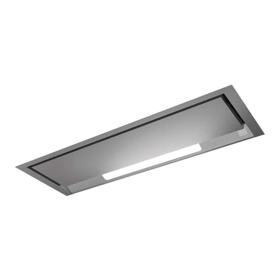
- Page 1 Istruzioni per l’uso e l’installazione Cappa Instructions for use and installation Cooker Hood Mode d’emploi et installation Hotte de Cuisine Premium 610 - 910...
-
Page 2: Table Of Contents
Libretto di Istruzioni INDICE CONSIGLI E SUGGERIMENTI.............................. . 3 CARATTERISTICHE................................4 INSTALLAZIONE ..................................6 USO......................................8 MANUTENZIONE .................................. . 9 Instructions Manual INDEX RECOMMENDATIONS AND SUGGESTIONS ........................11 CHARACTERISTICS ................................12 INSTALLATION..................................14 USE ......................................16 MAINTENANCE ...................................17 Manuel d’Instructions SOMMAIRE CONSEILS ET SUGGESTIONS............................19 CARACTERISTIQUES.................................20 INSTALLATION..................................22... -
Page 3: Consigli E Suggerimenti
CONSIGLI E SUGGERIMENTI INSTALLAZIONE • Il produttore declina qualsiasi responsabilità per danni dovuti ad installa- zione non corretta o non conforme alle regole dell’arte. • La distanza minima di sicurezza tra il Piano di cottura e la Cappa deve essere di 650 mm. •... -
Page 4: Caratteristiche
CARATTERISTICHE Ingombro Ø150 0-170 Componenti Rif. Q.tà Componenti di Prodotto Corpo Cappa completo di: Comandi, Luce, Gruppo, Ventilatore, Filtri quadrato ssazione Flangia ø 150 Pro lo chiusura Rif. Q.tà Componenti di Installazione Viti 4 x 16 Viti M5 x 16 Viti 3,5 x 9,5 Q.tà... - Page 5 Ø150 0-170...
-
Page 6: Installazione
INSTALLAZIONE Foratura Piano di supporto e Montaggio Cappa Il montaggio ed il collegamento devono essere reali ati da un istallatore qualificato* (*) Il non rispetto di questa condizione provocherà l’annullamento della garanzia del cos- truttore e di qualsiasi ricorso i caso di incidente. Attenzione : Usare dei tasselli adatti al supporto, informarsi presso i fabbricanti, effettuare una sigillatura se necessario. - Page 7 • Forare la parte superiore del mobile. • Fissare i due supporti con le viti fornite. 15 min. - 30 Max. X = Epaisseur porte (Come la posizione del taglio) • Posi ionare la valvola di non-ritorno (Rif. 9) sull’uscita dell’apparecchio.
-
Page 8: Uso
Quadro Comandi TASTO FUNZIONI ON/OFF Motore Attiva e a rresta il m otore d’a spirazione. S ul dis play v iene visualizzato lo step di velocità precedentemente impostata. Decrementa la velocità del motore: V3 →V2 → V1 elocità Velocità + Incrementa la velocità... -
Page 9: Manutenzione
MANUTENZIONE Pulizia dei Confort Panel • Aprire il c onfort panel agendo sulle apposite manopole, sgan- ciarlo facendo una leggera pressione sulla parte posteriore. • Il confort panel non va assolutamente lavato in lavastoviglie. • Pulirlo e sternamente c on u n pa nno umido e de tersivo li quido neutro. - Page 10 Filtri antiodore (Versione Filtrante) SOSTITUZIONE • Non sono lavabili nè rigenerabili, vanno sostituiti ogni 4 m esi circa di utiliz zo o più f requentemente, pe r un uso pa rticolar- mente intenso. • Aprire il Confort Panel, agendo sulle apposite manopoline •...
-
Page 11: Recommendations And Suggestions
RECOMMENDATIONS AND SUGGESTIONS INSTALLATION • The manufacturer will not be held liable for any damages resulting from incorrect or improper installation. • The minimum safety distance between the cooker top and the extrac- tor hood is 650 mm. • Check that the mains voltage corresponds to that indicated on the rating plate ÿxed to the inside of the hood. -
Page 12: Instructions Manual
CHARACTERISTICS Dimensions Ø150 0-170 Components Ref. Q.ty Product Components Hood Body, complete with: Controls, Light, Blower, Filters square xing brackets Flange ø 150 mm Closing element Ref. Q.ty Installation Components Screws 4 x 16 Screws M5 x 16 Screws 3,5 x 9,5 Q.ty Documentation Instruction Manual... - Page 13 Ø150 0-170...
-
Page 14: Installation
INSTALLATION Drilling the Support surface and Fitting the Hood ny permanent electrical installation must comply ith the latest regulations concerning this type of instal- lation and a quali ed electrician must carry out the or . on-compliance could cause serious accidents or in ury and ould deem the manufacturers guarantee null and void. - Page 15 • o drill the outlet onto the top of the all furniture. • o x the 2 squares using the provided scre s. • o x the 2 squares using the provided scre s. 15 min. - 30 Max. X = Epaisseur porte Caution: The position of the cutting and the squares could be modified according to the position of the frame thickness 30 mm.
-
Page 16: Use
Control panel TOUCH CONTROL FUNCTION ON/OFF Motor Switches the ho od m otor on a nd off. T he la test se lected speed appears on the display. Decreases the suction speed: V3 → V2 → V1 Speed - Increases the suction speed: V1 → V2 → V3 Speed + Intensive speed Activates t he i ntensive sp eed f rom an y p reviously sel ected... -
Page 17: Maintenance
MAINTENANCE Cleaning the Comfort Panel • Open the comfort panel; turn the hooks and remove the panel by slightly pressing the rear side. • Do not wash the comfort panel in the dish washing machine. • It is recommended to use a neutral detergent liquid and a damp cloth when washing the outer surface of the comfort panel. - Page 18 Odour lters (Recirculation version) REPLACING ACTIVATED CHARCOAL FILTERS • These filters are not w ashable and cannot be regenerated, and must b e rep laced ap proximately every four months of o pera- tion, or more frequently with heavy usage. •...
-
Page 19: Conseils Et Suggestions
CONSEILS ET SUGGESTIONS INSTALLATION • Le fabricant décline toute responsabilité en cas de dommage dû à une installa- tion non correcte ou non conforme aux règles de l’art. • La distance minimale de sécurité entre le plan de cuisson et la hotte doit être de 650 mm au moins. -
Page 20: Caracteristiques
CARACTERISTIQUES Encombrement Ø150 0-170 Composants Réf. Q.té Composants de Produit Corps Hotte équipé de : Commandes, Lumière, Groupe, Ventilateur, Filtres Flasque ø 150 mm Pro l fermeture Réf. Q.té Composants pour l ’installation Vis 4 x 16 Vis M5 x 16 Vis 3,5 x 9,5 Q.té... - Page 21 Ø150 0-170...
-
Page 22: Installation
INSTALLATION Perçage Plan de support et Montage Hotte Montage et raccordement doivent être réalisés par un installateur* qualifié. (*) Le non-respect de cette condition entraîne la suppression de la garantie du constructeur et tout recours en cas d’accident. Attention: prendre bien soin d’employer les chevilles adaptées au support, se renseigner au près des fabricants, effectuer un scellement si nécessaire. - Page 23 • Percer le dessus du meuble haut. • Fixer les 2 équerres à l’aide des vis fournies. 15 min. - 30 Max. X = Epaisseur porte Attention: La position des équerres pourra être modifiée suivant la position du bandeau épaisseur 30 mm. (Comme la position de la découpe) •...
-
Page 24: Utilisation
UTILISATION Tableau des commandes TOUCHE FONCTIONS ON/OFF Moteur Actionne et arrête le moteur d’aspiration. Sur l’afficheur est visualisé le pas de la vitesse précédemment sélectionnée. Réduit la vitesse du moteur: V3 → V2 → V1 Vitesse - Augmente la vitesse du moteur: V1 → V2 → V3 Vitesse + Vitesse intensive Actionne la v itesse inte nsive en pa rtant d’... -
Page 25: Entretien
ENTRETIEN Nettoyage des Confort Panel • Ouvrir le confort panel, en intervenant sur le s boutons spécia- lement pr évus, puis le dé crocher e n e xerçant une lé gère pr es- sion sur la partie arrière. • Le c onfort pa nel ne doi t a bsolument pa s ê tre la vé a u la ve- vaisselle. - Page 26 Filtre anti-odeur (Version ltrante) REMPLACEMENT FILTRE AU CHARBON ACTIF • Ils ne sont pas lavables ni régénérables; les remplacer au moins tous les quatre mois d’utilisati o n ou plus f réquemment en cas • lement prévus. • • Retirer le ltre anti-odeur au charbon actif colmaté, en agissant •...
- Page 27 Filtre recyclage assemblé Recycling ÿlter Umluftbetrieb Aktivkohle-Filter Filtro riciclaggio riunito Filter verenigde recycling...
- Page 28 Ø200 0-170 PREMIUM 910 SM...
- Page 29 Ø200 0-170 PREMIUM 610 SM...
- Page 30 Premium Premium L > 1000 mm L > 700 mm L = 900 mm L = 600 mm...
- Page 31 50800 VILLEDIEU-LES-POËLES - France Tél. 02 33 91 26 50 - Fax 02 33 51 54 79 - e-mail : com.france@roblin.fr For outside France : Tel. +33 (0)2 33 91 26 57 - Fax. : +33 (0)2 33 51 54 79 e-mail : com.export@roblin.fr...
Need help?
Do you have a question about the Premium 610 and is the answer not in the manual?
Questions and answers