Table of Contents
Advertisement
Quick Links
VER 2. 0
2007. 7
DYNAMIC AUTO
350M/500M
OPERATION MANUAL
Visit our website at
www.hyundaiwelding.com
www.HDWELD.co.kr
HEAD OFFICE: ILSONG BLDG. 16th fl.157-37,
SAMSUNG-DONG, KANGNAM-KU, SEOUL, KOREA
TEL : (+82-2)6230-6062~5 FAX: (+82-2)522-2030
FACTORY
: 9-2, SAEUM-DONG, ICHEON-SI, GYEONGGI-DO, KOREA
TEL : (+82-31)636-3100 FAX: (+82-31)636-3957
Advertisement
Table of Contents
Troubleshooting

Subscribe to Our Youtube Channel
Related Manuals for Hyundai Dynamic auto 350M


Summary of Contents for Hyundai Dynamic auto 350M
- Page 1 VER 2. 0 2007. 7 DYNAMIC AUTO 350M/500M OPERATION MANUAL Visit our website at www.hyundaiwelding.com www.HDWELD.co.kr HEAD OFFICE: ILSONG BLDG. 16th fl.157-37, SAMSUNG-DONG, KANGNAM-KU, SEOUL, KOREA TEL : (+82-2)6230-6062~5 FAX: (+82-2)522-2030 FACTORY : 9-2, SAEUM-DONG, ICHEON-SI, GYEONGGI-DO, KOREA TEL : (+82-31)636-3100 FAX: (+82-31)636-3957...
-
Page 2: Table Of Contents
SECTION 9- ELECTRICAL DIAGRAM ----------------------------------------- 36 9-1. DYNAMIC AUTO 350M ------------------------------------------------------ 36 9-2. DYNAMIC AUTO 500M ------------------------------------------------------ 37 SECTION 10 - PARTS LIST ------------------------------------------------- 38 10-1. Main Assembly-Dynamic Auto 350M ------------------------------------------ 38 10-2. Main Assembly-Dynamic Auto 500M ------------------------------------------ 40 - 1 -... -
Page 3: Section 1 - Safety Precautions - Read Before Using
SECTION 1 - SAFETY PRECAUTIONS - READ BEFORE USING 1-1. Symbol Usage The symbols shown below are used throughout this manual to call attention to and identify possible hazards. When you see the symbol, watch out, and follow the related instructions to avoid the hazard. -
Page 4: Hazard In Welding Power While In Use
1-2-1. Hazards in Welding Power Source While in Use DANGER ELECTRIC SHOCK can kill. Touching live electrical parts can cause fatal shocks or severe burns. The electrode and work circuit is electrically live whenever the output is on. The input power circuit and machine internal circuits are also live when power is on. In semiautomatic or automatic wire welding, the wire, wire reel, drive roll housing, and all metal parts touching the welding wire are electrically live. - Page 5 DANGER HOT PARTS can cause severe burns. •Do not touch hot parts bare handed. •Allow cooling period before working on gun or torch. DANGER MAGNETIC FIELDS can affect pacemakers. •Pacemaker wearers keep away. •Wearers should consult their doctor before going near arc welding, gouging, or spot welding operations.
-
Page 6: Hazard Around Working Area While In Use
1-2-2. Hazards Around Working Area While in Use WARNING NOISE can damage hearing. Noise from some processes or equipment can damage hearing. •Wear approved ear protection if noise level is high. DANGER BUILDUP OF GAS can injure or kill. •Shut off shielding gas supply when not in use. •Always ventilate confined spaces or use approved air-supplied respirator. - Page 7 DANGER CYLINDERS can explode if damaged. Shielding gas cylinders contain gas under high pressure. If damaged, a cylinder can explode. Since gas cylinders are normally part of the welding process, be sure to treat them carefully. •Protect compressed gas cylinders from excessive heat, mechanical shocks, slag, open flames, sparks, and arcs.
- Page 8 WARNING FLYING METAL can injure face. •Welding, chipping, wire brushing, and grinding cause sparks and flying metal. As welds cool, they can throw off slag. •Wear approved safety glasses with side shields even under your welding helmet. DANGER WELDING can cause fire or explosion. Welding on closed containers, such as tanks, drums, or pipes, can cause them to blow up.
-
Page 9: Additional Symbols For Installation, Operation, And Maintenance
1-3. Additional Symbols For Installation, Operation, And Maintenance DANGER FIRE OR EXPLOSION hazard. •Do not install or place unit on, over, or near combustible surfaces. •Do not install unit near flammables. •Do not overload building wiring - be sure power supply system is properly sized, rated, and protected to handle this unit. -
Page 10: Section 2 - Definitions
SECTION 2 - DEFINITIONS 2-1. Manufacturer's Warning Label Definitions 1. Electricity, Electrical Hazard •Disconnect power supplies before opening control box or servicing electrical unit. ☞ Electric power must be checked before connection. ☞ Place must be enough space to handle the working job for safety purpose. 2. -
Page 11: Manufacturer's Rating Label
2-2. Manufacturer's Rating Label VER 2. 0 - 10 -... -
Page 12: Section 3 - Installation
SECTION 3 - INSTALLATION 3-1. Specifications Model Dynamic Auto 350M Dynamic Auto 500M TYPE HD-CV350 HD-CV500 Rated Input Power 18KVA,16KW 30KVA,25.5KW 3 Φ 220/380/440 ± 10% Input Voltage Frequency 50/60Hz 50/60Hz Rated Welding Current 350A 500A Rated Welding Voltage Output Current Range... -
Page 13: Selecting A Location
3-3. Selecting a Location 3-3-1. Dimensions and Weight Dimension(mm) Weight(Kg) MODEL Dynamic Auto 350M Dynamic Auto 500M 3-3-2. Site Selection CAUTION / Select an installation site which provides the following: 1. Correct input power supply (see unit nameplate) 2. Shielding gas supply (if applicable) 3. - Page 14 WARNING Fire or Explosion can result from placing unit on or over combustible surfaces ; Restricted Airflow can cause overheating and possible damage to internal parts. •Do not locate unit over combustible surfaces. •Maintain at least 300mm of space from rear of unit, 300mm from sides. •Do not place any filtering device over the intake air passages that provide airflow for cooling this part.
-
Page 15: Transporting Methods
3-3-3. Transporting Methods WARNING This unit is equipped with two eyelets for carrying purposes. •Do not touch live electrical parts. •Disconnect input power conductors from de-energized supply line before moving welding power source. •Falling equipment can cause serious personal injury and equipment damage. •Move unit with hand cart of similar device of adequate capacity. -
Page 16: Weld Output Connections
3-4-1. Weld Output Connections To obtain full rated output from this unit, it is necessary to select, prepare, and install proper weld cables. Failure to comply in any of these areas may result in unsatisfactory welding performance. This value shall relate to the minimum fitting range for welding cables according to table1 Minimum range of size Rated current in A Rated current in A... - Page 17 B. Weld Cable connections WARNING / ARCING can burn skin or damage electrical connections. •Do not touch live electrical parts. •Shut down unit before marking any weld output connections. •Do not change position of the welding cable connectors while welding. •Be sure the connectors are secure in receptacles before welding ▲Connect end of electrode holder cable to POSITIVE(+) weld output receptacle as follows: align keyway, insert plug, and rotate plug clockwise until it is...
-
Page 18: Receptacle Information
3-5. Receptacle Information 3-5-1. DYNAMIC AUTO 350M Front view of Wire feeder socket Socket Pin Number Socket Information Receptacle Socket A Signal of output voltage Socket B Signal of output current Socket C Voltage, Current COM3 Socket D Voltage, Current COM1 Socket E Sol. -
Page 19: Electrical Service Guide
3-6. Electrical Service Guide ITEM Dynamic Auto 350M Dynamic Auto 500M 3 Φ 220V/380V/440V ±10% Input Voltage Equipment Capacity at Rated Output 18KVA 30KVA Max Recommended Standard Fuse 100A or Circuit Breaker Rating In Amperes Min Input Conductor Size 14mm... -
Page 20: Electrical Input Requirements
3-7-1. Electrical Input Requirements. Operate the welding power source from a three-phase 50/60 Hertz, AC power supply. The input voltage must match one of the electrical input voltages shown on the input data label on the unit nameplate. Contact the local electric utility for information about the type of electrical service available, how proper connections should be made, and inspection required. -
Page 21: Section 4 - Operation
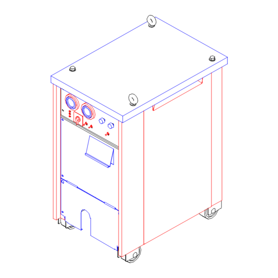
SECTION 4 - OPERATION 4-1. Front Panel Controls 4-1-1. DYNAMIC AUTO 350M ITEM DESCRIPTION Ampere Meter Welding current display Voltage Meter Welding Load & Noload voltage display Power Lamp Power on/off display Power Switch Power on/off control Crater Current Control Knob... -
Page 22: Dynamic Auto 500M
4-1-2. DYNAMIC AUTO 500M 30 33 1.2mm 1.4mm ITEM DESCRIPTION Ampere Meter Welding current display Voltage Meter Welding Load & Noload voltage display Power Switch Power on/off control Gas Lamp Gas on/off display Crater Current Control Knob Crater current control Crater Voltage Control Knob Crater voltage control Overload Lamp... -
Page 23: Section 5 - Sequence Of Operation
SECTION 5 - SEQUENCE OF OPERATION 5-1. Dynamic Auto 350M 5-1-1. Crater 'OFF', Pre-flow time 'ON' The diagram shows automatic control circuit of pre-flow time. As follows, Pre-flow time is '0' sec, when torch switch restarts('ON' state) while in gas after-flow. - Page 24 5-1-2. Crater 'ON' 5-1-3. Crater 'HOLD' VER 2. 0 - 23 -...
-
Page 25: Dynamic Auto 500M
5-2. Dynamic Auto 500M 5-2-1. Crater(Off) TORCH S/W 3SEC. MAGNATIC CONTACTOR 0.5SEC. AFTER-FLOW SOL. VALVE (GAS) Noload Voltage ANTISTIC WELD CURRENT DETECTOR OUT VOLT. SLOW DOWN HOT START MOTOR OUT AMP. WELDING 5-2-2. Crater(On) TORCH S/W 3SEC. MAGNATIC CONTACTOR 0.5SEC. AFTER-FLOW SOL. -
Page 26: Section 6 - Pcb Setting
SECTION 6 - PCB SETTING 6-1. DYNAMIC AUTO 350M PCB NAME : HDS-350 <Adjustment of Dip s/w> SELECT S/W S/W NO. FUNCTION adjustment of Simultaneous adjustment NO. 1, 2, 3 Individual adjustment Current,Voltage NO. 4, 8 Crater Outer starting signal input NO. - Page 27 <Adjustment of variable resistors> 1) Delay voltage (VR4) Adjustment of VR4 can vary the ball-shape of the wire rod end, which enables good arc start in next welding job ex) The size of ball-shape of the wire rod end is bigger as revolving to clockwise. Note: Too small(less than 1.4times of the wire rod) in adjustment makes slug at the end of wire rod.
-
Page 28: Dynamic Auto 500M
6-2. DYNAMIC AUTO 500M 6-2-1. EX Series EXCEL EX01 PCB EXCEL EX01A EXCEL EX01A EXCEL EX01A EXCEL EX01A EXCEL EX01A EXCEL EX01A Phase Balance Control - Don't Control Output Voltage Control SCR2 SCR1 EXCEL EX02 PCB R 25 Wire Feeding Rate Control SW 1 On/Off Select for Magnetic Contactor... -
Page 29: Section 7 - Function Diagram
SECTION 7 - FUNCTION DIAGRAM 7-1. DYNAMIC AUTO 350M VER 2. 0 - 28 -... -
Page 30: Dynamic Auto 500M
7-2. DYNAMIC AUTO 500M VER 2. 0 - 29 -... -
Page 31: Section 8 - Maintenance & Troubleshooting
SECTION 8 - MAINTENANCE & TROUBLESHOOTING 8-1. Routine Maintenance 8-2. Troubleshooting(Dynamic Auto 350M) TROUBLE CAUSE MEASUREMENT WHEN POWER 'ON', 1. POWER DOES NOT 1. CHECK INPUT VOLTAGE ON POWER LAMP, SUPPLY. MAGNETIC CONTACTOR. COOLING FAN DOES (3PHASE, 220V/380V/440V) NOT WORK 2. - Page 32 TROUBLE CAUSE MEASUREMENT 5. CHECK FUSE, IF NOT GOOD, 5. CONTROL FUSE(FU2) IS REPLACE IT WITH GOOD. WHEN POWER 'ON', BROKEN DOWN (250V, 3A) POWER LAMP, COOLING FAN DOES 6. CHECK VOLTAGE BETWEEN 6. POWER LAMP, FAN MOTOR NOT WORK CONNECTOR OF FAN MOTOR IS BAD LINE, 220VAC...
- Page 33 TROUBLE CAUSE MEASUREMENT 3. CONTROL(9P)CABLE IS 3. REPAIR CABLE DISCONNECTED 4. PCB IS BAD 4. REPLACE PCB 1. GAS DIFFUSER IN TORCH 1. ASSEMBLE RIGHTLY. GAS IS FLOWING IS ASSEMBLED BADLY BACKWARD TO WIRE 2. TORCH LINER IS 2. ASSEMBLE OR REPLACE LINE- FEEDER.
- Page 34 TROUBLE CAUSE MEASUREMENT ARC DOES NOT 1. VOLTAGE BETWEEN TORCH 1. CHECK & FASTEN CONNECTIO IGNITED. & BASE METAL IS NOT N OF TORCH, BASE METAL. DETECTED 2. CHECK PRESSURE LEVER OF 2. WIRE IS NOT FED. 3 PCB IS BAD 3.
-
Page 35: Troubleshooting(Dynamic Auto 500M)
8-3. Troubleshooting(Dynamic Auto 500M) BEFORE THE CHECK ! - Check the Power Lamp On - Check the Input Powerline Fuse & MCCB - Check the Input Connecting Power - Check the Power Switch On TROUBLE REMEDY No noload output voltage, Feeding motor On, 1. - Page 36 Overload(While welding within 10~20min.) 1. Check the fan 2. Be sure air inlet is cleared 3. Change the thermal switch Decrease welding voltage while welding 1. Check the basemetal & cable connection(Overheat) 2. Check the torch & cable connection(Overheat) Welding wire is going on, when welding 1.
-
Page 37: Section 9- Electrical Diagram
SECTION 9 - ELECTRICAL DIAGRAM 9-1. DYNAMIC AUTO 350M VER 2. 0 - 36 -... -
Page 38: Dynamic Auto 500M
9-1. DYNAMIC AUTO 500M ☞ OPTION : EX03 PCB & CT1 INCLUDED VER 2. 0 - 37 -... -
Page 39: Section 10 - Parts List
SECTION 10 - PARTS LIST ain Assembly 10-1. M - Dynamic Auto 350M VER 2. 0 - 38 -... - Page 40 ITEM SPECIFICATION Q'TY REMARK Top Cover DYNAMIC 350 Rear Panel DYNAMIC 350 Side Panel DYNAMIC 350 Fan Panel DYNAMIC 350 PCB Cover DYNAMIC 350 Front Panel DYNAMIC 350 Output Terminal Bracket DYNAMIC 350 Base Ass'y DYNAMIC 350 Main TR DYNAMIC 350 Reactor DYNAMIC 350 Ampere Meter...
-
Page 41: Main Assembly-Dynamic Auto 500M
ain Assembly 10-2. M (EX PCB Type)- Dynamic Auto 500M VER 2. 0 - 40 -... - Page 42 ITEM SPECIFICATION Q'TY REMARK Top Cover DYNAMIC SERIES Rear Panel DYNAMIC SERIES Side Panel DYNAMIC SERIES Fan Panel DYNAMIC SERIES Side Frame(RH) DYNAMIC SERIES Side Frame(LH) DYNAMIC SERIES P.C.B Case DYNAMIC SERIES Control Panel DYNAMIC SERIES Front Panel DYNAMIC SERIES Output Terminal Bracket DYNAMIC SERIES 11,12...
- Page 43 ITEM SPECIFICATION Q'TY REMARK Connector MS3102(20-16P) Condenser Ass'y Gas Hose Magnetic Contactor Reed Switch AMS 39 500A:TM150SA-6 / PFT1503N S.C.R 600A:T61-200-08 Thermostat EX06 Control TR(1 Φ ) ATR501(500VA) Diazed Fuse & Holder 600V,30A Control TR(3 Φ ) ATR101(100VA) Impeller 350mm Fan Motor AC 220V 220V Outlet...
Need help?
Do you have a question about the Dynamic auto 350M and is the answer not in the manual?
Questions and answers