
Related Manuals for Audio Pole PX-360


Summary of Contents for Audio Pole PX-360
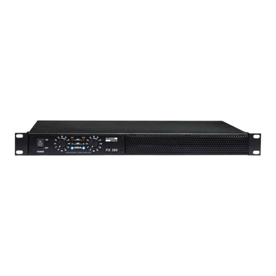
- Page 1 PX-360 PROFESSIONAL POWER AMPLIFIER PX-360 PROFESSIONAL STEREO AMPLIFIER ...
-
Page 2: Important Safety Instructions
Important Safety Instructions This symbol, wherever used, alerts you to the presence of un-insulated and dangerous voltages within the product enclosure. These are voltages that may be sufficient to constitute the risk of electric shock or death. This symbol, wherever used, alerts you to important operating and maintenance instructions. POWER SUPPLY Ensure that the insource voltage (AC outlet) matches the voltage rating of the product. -
Page 3: Table Of Contents
Index 1. Introduction …………………………………………………………………….….. 2. Main Features………………………………………………………………………. 3. Functions …………………………………………………….…………………….. 4. Applications ………………………………………………...……………….…….. 5. Technical Specifications ……………………………...……………………...…… 6. Warranty ……………………………………………………………………….…… ... -
Page 4: Introduction
The PX-360 has a high efficiency thanks to his Class-D technology and can deliver 2 x 180 W RMS on 4 Ohms. It also works securely with 2 Ohms loads. A Bridge mode enables to power a mono device like a subwoofer or a low impedance loudspeakers line. -
Page 5: Functions
Functions FRONT PANEL 1 – POWER Power switch. 2 – Volume Volume control. 3 – POWER ON Power indicator. 4 – SIG Signal indicator. 5 – PROT Protection indicator. If the amplifier fails, the Led lights up, the output being automatically muted. Check the cable connection between the amplifier and the speaker. - Page 6 Functions REAR PANEL 1 – Mains and fuse Main power supply socket. Make sure that the cable plug is correctly inserted in the socket. The compartment located below the socket contains the fuse. In the event of change, it is imperative to use a fuse with identical electrical characteristics under threat of damage to the unit.
-
Page 7: Applications
Applications Two work modes can be selected: Stereo or Bridge Mono. Stereo mode • In Stereo mode, channel 1 and 2 work separately using their own connectors and controls. ... - Page 8 Applications Bridge Mode • In Bridge Mono mode the power capacities of the two channels are cumulated to be used with one single load. The input signal must be connected to channel 1 of the amplifier. Channel 2 is not used and its volume control must be set to zero.
-
Page 9: Technical Specifications
Technical Specifications 2 Ω (EIAJ) 2 x 400 W Stereo Power 4 Ω (RMS) 2 x 180 W 8 Ω (RMS) 2 x 100 W 8 Ω (RMS) 360 W Bridge Mode Power ... -
Page 10: Warranty
Warranty This device is warranted parts and labor against any manufacturing defects for a period of two years from the date of purchase by the first user. Conditions 1. The unit has been installed and implemented by observing the safety instructions in this operating manual.
Need help?
Do you have a question about the PX-360 and is the answer not in the manual?
Questions and answers