Table of Contents
Advertisement
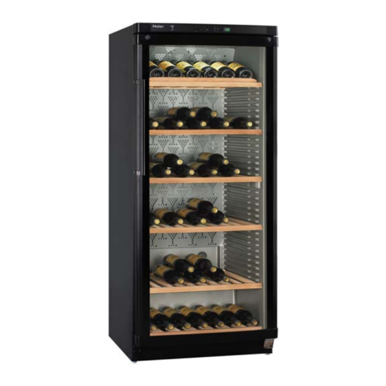
Wine cellar
SERVICE MANUAL
●Features
●Optimized for Preservation of Wine Flavors.
●Adjustable feet and Remove roller.
●Adjustable temperature display from 6℃ to 18℃.
●Active carbon deodorization implement .
●Interior light.
●Interior fan keep well-proportioned temperature.
●Store Wine quantity:174 bottle.
CAUTION
READ THIS MANUAL CAREFULLY TO
DIAGNOSE TROUBLE CORRECTLY
BEFORE OFFERING SERVICE .
MODEL:
Haier Group
JC-398G
Advertisement
Table of Contents

Related Manuals for Haier JC-398G


Summary of Contents for Haier JC-398G
- Page 1 CAUTION READ THIS MANUAL CAREFULLY TO DIAGNOSE TROUBLE CORRECTLY BEFORE OFFERING SERVICE . Wine cellar SERVICE MANUAL JC-398G MODEL: ●Features ●Optimized for Preservation of Wine Flavors. ●Adjustable feet and Remove roller. ●Adjustable temperature display from 6℃ to 18℃. ●Active carbon deodorization implement .
-
Page 2: Table Of Contents
Contents 1. Cont ents……………………………………………………………………….……1 2. S afety cautions…..…………………………………………………………………2 3. S pecifications……………………………………………………………………..3 4. Installation and accessory parts………………………………………….…..5 5. Parts identifications ………………………………………………. ……………..8 5.1 Control panel……….……………………………………………………..8 5. 2 Connectting wires………………………………………………………..9 ix the power wire and ballast 5. 3 F ………………………………………... 10 The compressor…… 5. -
Page 3: S Afety Cautions
2 Safety Precautions Read al l of the instructions befo re us ing th is appl iance. When us ing th is app liance, al ways exercise basic safety precautions, including the following: 1. Use this appliance only for its intended purpose as described in this uses and care guide. 2. -
Page 4: Specifications
Specifications WINE CELLAR Model JC-398G Photo Commercial brand Haier Product description WINE CELLAR Type of Appliance ( FS= freestanding BI= built-in) Energy efficiency class Climate class (N= + 18-32 °C T=+ 18-43 °C) Freezer compartment / Star rating Approvals (VDE / TÜV / IMQ / NF / ÖVE / DEMKO etc.) - Page 5 4 Fascia panel / Handle (w / b / g / s) Black Inside door/-drawers (w= white t= transpar.) - / - Door: F= Flat / R= Rounded / S= Streamline Hinged r / reversible (r =right l =left) / reversible) Deco frame: mm 90 panel thikness till:...
-
Page 6: Installation And Accessory Parts
Installation and Accessory Parts Unpacking Your Wine cellar 1.Remove al l p ackaging material; this includes the foam bas e an d al l adh esive tape holding the Wine cellar accessories inside and outside. 2.Inspect a nd r emove any remains of p acking, tape o r p rinted m aterials b efore powering on the Wine cellar. -
Page 7: Electrical Requirement
6 ·Do not over fill wine cellar for proper internal air circulation. Electrical Requirement Make sure there is a suitable power Outlet (220~240V) with proper grounding to power the wine cellar. Make sure there is effective grounding for the wine cellar, this is a dangerous practice since it provides no effective grounding for the freezer and may result in shock hazard. - Page 8 Your Freezer has 5 removable even shelves and 1 removable catercorner shelf. It allows you to store wine more accessibly or you can remove it if not needed. 3.Defrosting and cleaning The Wine cellar ·Defrost w henever the f rost becomes 1/4” t hick. N ever u se a sharp or metallic instrument to remove the frost as it may damage the cooling coils.(A punctured coil will void the warranty) ·...
-
Page 9: Parts Identifications
8 Parts identifications Control panel Fan and Handle evaporator clapboard Glass door Adjustable feet 1. Control panel a. Firstly, loosen the philip screw on the top Hold the control panel, meanwhile push Hinge, the door should open for 135°when the wiring harness button with your loosening the right side philip screw. -
Page 10: Connectting Wires
One side of the signal wire was connecting The socket of sensor wire is connecting with the control panel, the other side was connecting with the display panel, please refer to with the middle of the display panel. Take it the signal wire to take it apart. -
Page 11: Fix The Power Wire And Ballast
10 When you take the box cover apart, as on the picture, the blue one is lamp wire, connecting with the connect wire and ballast wire. The red one is fan wire, connecting with the control wire. The white one is connect wire, connecting with heater wire. -
Page 12: The Compressor
4.The compressor The assemble step of the compressor accessory There is buckle on the Water box is showing on the picture. The earth wire is connecting to to fix on the compressor, and the compressor, the live wire and zero wire is connected also some anti-shock material to the compressor power panel, rotate the plastic bolt to fix between them. -
Page 13: Control Panel Principle
12 Control panel principle Brief description of control panel principle about :JC-398G : While you are entering the Adjustable temperature display temperature by pressing the temperature buttons about 3 seconds, the set temperature will flash on the display. To reduce the temperature, press the bottom button “▼”. -
Page 14: System Flow Chart
System Flow Chart The ref rigeration system o f di rect cooling s ingle-system cooler belongs t o t he c ategory of a si ngle-temperature and single-control refrigerating s ystem with one evaporat ors and i s controlled by a single temperature control. -
Page 15: System Flow Scenograph
14 System flow scenograph... -
Page 16: Circuit Diagram
Circuit diagram 1. Bri ef principle di agram Notes: 1. If the wine cellar has been placed in a horizontal or tilted position for any period of time wait 24 hours before plugging the unit in. 2.The alarm w ill sound w hen the appliance i s s witched on for th e first time and when t he a ppliance i s warm. -
Page 17: Connect Diagram
16 2.Connect di agram... -
Page 18: 0.3 Control Panel Diagram
3. Control panel diagram 1/2W 17... -
Page 19: 0.4 Display Board Diagram
4. Display board diagram R39220 R40220 R41220 16V/220U R42 220 2SA1037AK R9 4.7K R3 2K R4 2K HEAT R5 2K LAMP R8 4.7K 2SA1037AK 5267-5A 2SA1037AK LED3 LED2 R6 10K R10 4.7K 2SA1037AK R7 4.7K LED1 TOT-5371 2SA1037AK TEST BUZZ1 PS1740P02C 2SC2412K 2SA1037AK... -
Page 20: Normal Problems
Normal peoblems Problems Reasons Removing methods 1. Fuse is broken 1. C heck if the re is sho rt c ircuit 2. T he c ontact of p lug, sock et, an d and solve it, if not, change capable cable is not good. - Page 21 20 Compressor 1. Supplement a st abilizer, adj ust buzzes and 1. Voltage is too low. to rated value. cannot be 2. Change starting relay. started, 2. Starting relay out of order. 3. C hange compressor. 3. The st arting coi l o f st arting thermal protection unit motor is broken.
- Page 22 Electricit leakage 1. The service time is too long. 1. Change temperature controller. 2. Use brush to remove dust. temperat 2. The environment is too dirty. 3. Make the te mperature dry and 3. Humidity is too high. control the environment humidity. controlle Tempera 1.
-
Page 23: Trouble Shooting
22 Trouble shooting 1.Compressor does’t start... -
Page 24: Poor Cooling
2.Poor cooling Poor cooling Check the diaplay temperature Change to lower nomber whether it is setted at 18°C Whether the rear side and the top is too close to the wall Avoid these Whether the cellar is under matters which sunlight directly will affect heat radiation of... -
Page 25: Failure Code Display
Failure code display Error Description and reason Solutions indicator Sensor A is failure (broken circuit or Check sensor A and it’s connecting open circuit). status, replace sensor if necessary. Red indicator is light with buzzing. Sensor B is failure (broken circuit or Check sensor B and it’s connecting open circuit). - Page 26 28...
Need help?
Do you have a question about the JC-398G and is the answer not in the manual?
Questions and answers