Table of Contents
Advertisement
Quick Links
Advertisement
Table of Contents

Subscribe to Our Youtube Channel
Related Manuals for Ingrasys N3211E

Summary of Contents for Ingrasys N3211E
- Page 1 N3211E User’s Manual Version 1.0...
-
Page 2: Table Of Contents
Table of Contents Important Notices – Read Before Use ................2 Overview ......................... 2 Package Contents ......................3 Installation ........................4 Hardware Installation ............................... 4 Software Installation ................................ 4 Discover IP Cameras ................................ 4 Assigning IP Address to the device ..........................5 Discovering devices in Windows Network ........................ -
Page 3: Important Notices - Read Before Use
N3211E is equipped with 4mm board type lens for wide viewing angle that allows users to recognize much broader range at the single sight. -
Page 4: Package Contents
Package Contents N3211E Power Adapter (Optional) Quick Installation Guide Hardware Pack Product CD Warranty Card VIP Card (Optional) -
Page 5: Installation
Installation Hardware Installation Define the type of network device. If the network device supports PoE (Power over Ethernet) function, simply connect the camera to it via Ethernet cable. If not, the connections to the network device (via Ethernet cable), and DC 12V adapter are required. Software Installation Discover IP Cameras Discovery Tool is a utility provided for not only searching and displaying the available IP cameras information... -
Page 6: Assigning Ip Address To The Device
Assigning IP Address to the device The steps of applying this search tool are described as below. 1. Launch Discovery Tool (ingrasysDiscovery.exe) 2. Assign IP address The selection is based on a single or multiple camera devices. [Set IP] This is applied to one specific camera selected from the Device List. Step1: Select one specific camera device Step2: Input desired IP information The default settings of account /password are Admin / Admin. - Page 7 This is applied to a group of specific cameras selected from the Device List. Step1: Select specific cameras Step 2: Input Account / Password The Ingrasys default account information is Admin / Admin. If the values have been re-set, please enter the set values. Step 3: Input IP information...
-
Page 8: Discovering Devices In Windows Network
Discovering devices in Windows Network If the IP camera is installed in a network with DHCP and UPnP services, after obtaining an IP address from DHCP server, it can then be discovered in “Windows Network” of a client PC, see figure below. The reason for ... -
Page 9: Activex Add-On Installation
ActiveX add-on Installation It is recommended to use Internet Explorer 8 or later as the primary browser to access the IP cameras website. The first-time access to the camera webpage will be prompted to install the ActiveX. To allow the installation, click “Install”... - Page 10 If, however, there is not any prompted message or ActiveX cannot be installed at all, it is needed to change the IE security level and settings. <Example> Internet Explorer 9: Internet Options Security Custom level Ensure the “Download signed ActiveX controls” setting is either “Enable” or “Prompt” selected.
-
Page 11: Accessing The Camera
With the correct installation and IP settings, the camera device can be approached via network. There are three ways to view the live video from the camera. 1. Internet Explorer Launch IE browser and input the IP address of the camera or, Click on “Browse” button on the selected IP camera address from Ingrasys Discovery Tool... - Page 12 The example given below is the live video displayed with QuickTime player. 3. NVR / CMS Software Ingrasys IP cameras are ONVIF conformant products. Most of ONVIF conformant NVR / CMS software can retrieve the video from the cameras for both live view and recording. For more details...
-
Page 13: The Live View Page
The Live view page The following illustration shows you the front page of Ingrasys IP camera website. Quick Index Live Window Video Stream Operations Live Video Window Quick Functional Buttons... - Page 14 Snapshot: Press the button to capture an image photo Record: Press the button to start recording. Press again to stop it. Record Path: set up a file path that video clips and snapshots can be stored. Full screen: Press the button to enter the full screen mode. Press ESC key to return. Manual trigger: Press the button as triggering an event.
-
Page 15: Video & Audio
Video & Audio This section describes how to configure the video streaming of the device and the related camera image configurations. Users with Administrator or Operator authority (see System User Management) are able to do these configurations. Click on “Setup” of Quick Index to enter the “Video & Audio” page shown as below. There are 3 sub-settings under “Video &... - Page 16 Camera Setting Image Setting Brightness: the luminance of image view. Default value is 8; adjustable from 0 to 16. Contrast: the ratio of luminance of white to black. Default value is 8; adjustable from 0 to 16. Saturation: colorfulness of a color related to its own brightness. Default value is 8, adjustable from 0 to 16.
- Page 17 Day/Night Day/Night Mode: Switch the video images for Day (plenty of light) or Night (Low light) scene. In default “Auto” mode, camera will switch to Day or Night vision according to the light intensity. The Day / Night modes contain 2 actions: switching IR Filter On / Off, and image hue Color / Mono. In day mode, the IR filter is switched in to avoid the image sensor from receiving the infrared, thus the true color image is provided.
- Page 18 : represents the Day mode : represents the Night mode The setting items with the Day or Night mode symbol will be altered along with the setting of Day/Night mode. The examples are illustrated as below.
- Page 19 Video Setting Video Stream This tab provides detailed stream configurations. These settings can affect video size, quality. The maximum transmission performance can be expected under the condition of full network bandwidth. The camera supports up to 2 video streams. Each stream can be configured with following items.
- Page 20 Video Format: H.264, MPEG4 and MJPEG are available for the selection. The demand of bandwidth and storage requirement differs from the selection of video format. In the request of same video quality, H.264 contributes to less bandwidth and storage requirement, which can be more efficient than MPEG4 or MJPEG.
- Page 21 Privacy Mask Privacy Mask can block out the specific areas from view. The blocked areas will not be seen in both live view and recorded video clips and the total of 8 profiles can be created to the list. To create Privacy Mask, simply input Privacy Mask Name and click “Add New” button and then apply it to complete the addition.
-
Page 22: Network Configuration
Network Configuration The IP Camera acts as one of the network devices. It allows user to configure the network functionalities based on applications. This section will describe the network configurations. Fundamentally, for instance, the IP assignment of the device can be done via DHCP server, static IP option or PPPoE to obtain IP from the service provider. - Page 23 Network Connectivity This page provides the connectivity configuration, so that IP camera can be accessed without necessarily providing the numerical IP address. Enable UPnP Service: With UPnP enabled, IP camera device can be easily discovered in Windows Network (My Network Places). See “Discover devices in Windows Network” in previous section. Enable DDNS Service: By registering this sort of service, camera can be assigned and accessed over Internet with a hostname instead of IP address.
- Page 24 Access Port The Web access port can be changed in this page. Default HTTP and HTTPs port numbers are 80 and 443 respectively. The configuration of these port numbers provides the simple security. HTTP port / HTTPS port: By default, the HTTP and HTTPs ports are set to 80 and 443 respectively. They can also be assigned to another port number between 1025 and 65535.
- Page 25 NOTE The multicast stream can be triggered by a network client (e.g. choosing “Multicast” from the live view page) whereas “Always Multicast” option is not enabled. This mechanism is known as “Multicast On Demand”. In this mode, multicast stream starts when one or more clients request. It stops automatically when the last client leaves the multicast group.
-
Page 26: Recording
Recording This section provides the recording configuration on the camera. Unlike the recording function (Quick Functional Button) on the live view page, video can also be recorded to the local network storage (Samba) according to a time based schedule. There are 2 subdirectories in the “Recording” category: −... - Page 27 Add / Edit Recording Plan Plan Name: Identifier of the recording plan Video Source: The selection of the video source to be recorded. Options: None or Stream 2. NOTE: Stream 2 should be enabled prior to recording plan. Maximum File Size: This option defines the maximum file size of each video clip. Destination: The stored path for the recording file Select All: 24/7 continuous recording Scheduled Pattern: User-defined time frame...
-
Page 28: Event Management
Event Management Event management describes the handling of events with the corresponding actions. A common case can be exampled is storing a captured image to a local network storage (Actions), when there is a Motion Event (Trigger Condition). This chapter gives the configurations of Triggers (what to detect?) and Actions (“what to send”... - Page 29 Server Name: Identifier of the event server Server Type Email: Send the media file via email when an event is triggered. • Mail Server Address: Enter a host name or IP address of the email server. • User Name: Enter the user name of the email account. •...
- Page 30 Motion Configuration There are 3 MD (Motion Detection) areas can be enabled. Each MD can be individually enabled/disabled, defined the covering range and trigger sensitivity. To enable and verified the MD, follow the steps provided below. 1. Check the box to enable the motion area 2.
- Page 31 Event List List a summary of configured events. That is the selection of trigger condition(s) and the corresponding actions, as well as the scheduling. Up to 10 event objects can be configured. To begin with it, click on “Add New” button to extend for the detailed configurations. Event Name: Enter an event name, e.g.
- Page 32 • Periodically: Enable the system to perform the set Action periodically by entering number of minute(s) in the field as below. Action: Selection of responding actions • Upload files to a server: There are two drag-down selections, Event Server and Media Type. The Event Server indicates the file destination such as the FTP and Samba, and the file type includes snapshot image and video clip.
-
Page 33: Examples Of Event Handling
Examples of Event Handling The following cases are provided as the examples of Event Handling. Scenario While viewing live video, user can manually trigger an event anytime simply by pressing the button, on the web page. It will send email to the specified email accounts with the captured pictures. The configurations are illustrated as below: Step 1: Add Event Server •... - Page 34 Step 3: Configure Event List • On Event List page, click on “Add New” button. • Enable and configure this event - Event of manual triggering - Check the box to enable this event. It can be deselected later with all the following settings remained.
-
Page 35: System Options
System Options System Options provide users to obtain and configure the system settings of the IP camera system. It contains the page of System Information, Date and Time, User Management, Maintenance and Log Service. The details about each subcategory will be described as below. System Information The page gives details of the IP camera system. - Page 36 Date and Time This section describes the date/time adjustment for the IP camera system. The ways to adjust the IP camera’s date/time can be automatic (Synchronize with NTP Server / PC) or manual settings. Current Date & Time Display current system date/time of the IP camera. The date format can be changed from the drop-down list in Configure Date &...
- Page 37 User Management By default, the access to the camera is not user authenticated. For security, the IP camera should be restricted to account only accesses. It is able to enable user accounts, as well as to manage the added users in this page.
- Page 38 NOTE The backup file can be applied to other Ingrasys IP cameras, so users won’t need to configure each device. It is recommended to switch the IP setting to DHCP mode before exporting the backup file. Otherwise, all IP cameras will have the same IP address.
-
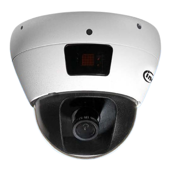
Page 39: Connectors & Led
Connectors & LED Physical appearance and connectors Product Front View Product Rear View... -
Page 40: Led Indicators
LED Indicators There are 2 type of LED indicators; RJ45 LEDs (back panel) and System LED (front, bicolor). These LEDs can help to recognize the current device status. RJ45 LEDs for Network Status: LED1 (Green) LED2 (Amber) 10 Link / Traffic Steady ON / Flashing 100 Link / Traffic Steady ON / Flashing... -
Page 41: Troubleshooting
Troubleshooting Check firmware version Firmware version may imply the functionalities’ updates or availability in the camera system. Therefore, in the first step of troubleshooting and then reporting, it helps to locate the found issues. Newer version firmware may have these issues corrected. The version code can be found in Setup ->... - Page 42 Figure 1 Figure 2 Figure 3...
-
Page 43: Recover Device Settings
Recover device settings In some cases, camera system does not respond to any operation. A certain recovering processes would help to get the unit back to initial status, so that it can resume operable / configurable. This will be the operations on the “Reset Button”. -
Page 44: Technical Specifications
Technical Specifications *Design and specifications are subject to change without notice. Model No. N3211E Types of camera Description Ultra Mini 2MP Full HD IR Dome IP Camera Image Sensor 1/2.7” progressive CMOS sensor Image Pixel 2.0 Megapixel Lens type Board mount, 4.0mm, Fixed IRIS...
Need help?
Do you have a question about the N3211E and is the answer not in the manual?
Questions and answers