Table of Contents
Advertisement
Quick Links
Advertisement
Table of Contents

Related Manuals for First Alert DVRAHD-0810


Summary of Contents for First Alert DVRAHD-0810
-
Page 1: User Manual
USER MANUAL HD-TVI Digital Video Recorder DVRAHD-0810 | DVRAHD-0820 | DVRAHD-1620... -
Page 2: Introduction
First Alert has been helping families and businesses stay safe for over 50 years. By having a First Alert Security System, you’re taking the first step in protecting your home or business from damage or theft. - Page 3 Thank you for purchasing our product. If there is any question or request, please do not hesitate to contact dealer. The figures in this manual are for reference only. This manual is applicable to the models listed in the following table. Series Model Type DVRAHD-0810 DVRAHD-XX DVRAHD-0820 Network DVR DVRAHD-1620 Page 3...
-
Page 4: Table Of Contents
INTRODUCTION Table of Contents ection eScription Introduction Safety Product Overview Package Contents Camera Power Connections Front Panel IR Remote Control Operation USB Mouse Operation Input Method Description Rear Panel Initial Setup Start Up and Shut Down Setup Wizard 15-16 Adding and Connecting IP Cameras 17-18 Editing Connected IP Cameras and Configuring Live View... -
Page 5: Introduction
INTRODUCTION Table of Contents ection eScription Alarm Settings Setting Motion Detection Detecting Video Loss Detecting Video Tampering Setting All-day Video Quality Diagnostics Handling Exceptions Setting Alarm Response Actions 57-58 Network Settings Configuring General Settings Configuring Advanced Settings 59-67 Checking Network Traffic Configuring Network Detection 68-69 HDD Management... -
Page 6: Safety
Notice: Only peripherals complying with FCC class B limits may be attached to this equipment. Operation with non-compliant peripherals or peripherals not recommended by First Alert / BRK Brands, Inc. is likely to result in interference to radio and TV reception. Changes or modifications to the product, not expressly approved by First Alert / BRK Brands, Inc., could void the user’s authority to operate the equipment. -
Page 7: Product Overview
PRODUCT OVERVIEW Package Contents What s in the Box* DVR Device You will Need... • Monitor or Television with HDMI or VGA inputs • VGA cable (If not using included HDMI cable) PC Software IR Bullet Camera* IR Dome Camera * 12V AC Adapter(s) &... -
Page 8: Camera Power Connections
Tighten Ring and Thumb Screw. Step 3: Rotate camera body using Adjusting Point 3 to the proper view Use First Alert Cameras Only angle making sure the Camera Shield is always on top and parallel to the ground so the image is level in the Live View Screen. See “Camera Orientation”... -
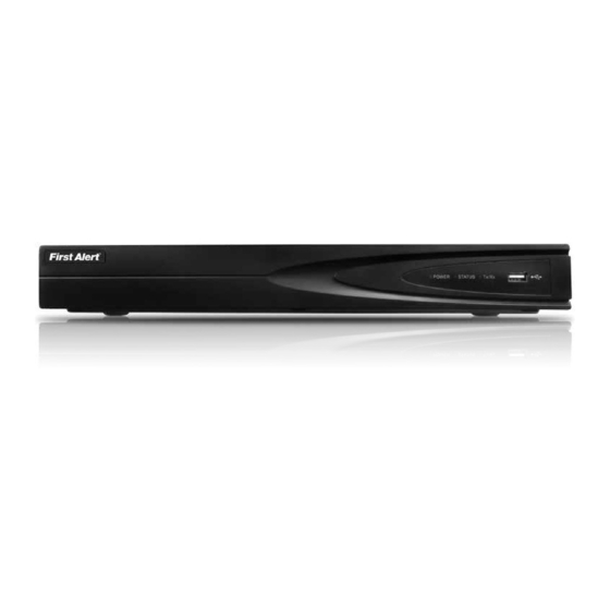
Page 9: Front Panel
PRODUCT OVERVIEW Front Panel POWER STATUS Tx/Rx unction eScription Power Displays yellow when power is on Status Blinks red when data is being read from or written to HDD Tx/Rx Blinks yellow when network connection is functioning properly IR Receiver Receiver for IR remote Universal Serial Bus (USB) ports for additional devices such as USB mouse and USB Hard Disk USB Interfaces... -
Page 10: Ir Remote Control Operation
PRODUCT OVERVIEW Remote Control The remote control provided requires two (2) AAA batteries. Install batteries before operating. unction eScription Power Power on or off Enable/disable remote control MENU Alphanumeric Buttons Same as alphanumeric buttons on front panel PLAY Same as MENU button on front panel MENU Same as ESC button on front panel Same as REC button on front panel... -
Page 11: Usb Mouse Operation
PRODUCT OVERVIEW USB Mouse A standard three-button (left/right/scroll-wheel) USB mouse can be used with this DVR. To use a USB mouse, simply plug the USB mouse into one of the USB interfaces on the front panel. NOTE : The DVR will automatically detect a compatible mouse. Follow the steps below to operate the USB mouse. -
Page 12: Input Method Description
PRODUCT OVERVIEW Input Method Description To enter text or numerical data, the system uses a virtual keypad. In fields where letters or numbers can be entered, you can switch between various formats — numbers, upper case letters (ABC), and lowercase letters (abc). Soft Keyboard eScription English... -
Page 13: Rear Panel
PRODUCT OVERVIEW Rear Panel POWER VIDEO OUT HDMI D+ D- AUDIO RS-485 VIDEO IN unction eScription Video In BNC interface for TVI and analog video input. Audio In RCA connector Audio Out RCA connector DB15 connector for VGA output. Display local video output and menu. HDMI HDMI video output connector. -
Page 14: Initial Setup
INITIAL SETUP Proper Startup Proper startup and shutdown procedures are crucial to expanding the life of the DVR. Check that the voltage of the extra power supply is the same with the DVR’s requirement, and the ground connection is working properly. Start Up and Shut Down Starting Up 1. -
Page 15: Setup Wizard
INITIAL SETUP Setup Wizard Quick Startup After the initial system power up, the Setup Wizard will automatically launch. Please select the system language in the drop- down list on your demand. To skip the Setup Wizard temporarily, click the “Cancel” button. Click “Next”... -
Page 16: Setup Wizard
INITIAL SETUP Network Wizard Click Next button after you having configured the network parameters, which will take you to the Advanced Network Setup Wizard window. Set the parameters of port No., ezviz Cloud, Auto UPnP or DDNS if required. Click Next button after configuring the advanced network parameters, which will take you to the HDD HDD Management... -
Page 17: Adding And Connecting Ip Cameras
INITIAL SETUP Adding and Connecting the IP Cameras The main function of the DVR is to connect the network cameras and record the video got from it. So before you can get a live view or record of the video, you should add the network cameras to the connection list of the device. - Page 18 INITIAL SETUP 4. To add other IP cameras: 1) Click the Custom Adding button to pop up the Add IP Camera (Custom) interface. 2) You can edit the IP address, protocol, management port, and other information of the IP camera to be added. 3) Click Add to add the camera OPTION 2: 1.
-
Page 19: Editing Connected Ip Cameras And Configuring
INITIAL SETUP 3. (For the encoders with multiple channels only) check the checkbox of Channel No. in the pop-up window, as shown in the following figure, and click OK to finish adding Editing the Connected IP Cameras and Configuring Customized Protocols After the adding of the IP cameras, the basic information of the camera lists in the page, you can configure the basic setting of the IP cameras. -
Page 20: Live View
LIVE VIEW Live View Introduction What is Live View? Live view shows you the video image from each camera in real time. The DVR will automatically enter Live View mode when powered on. It is also at the very top of the menu hierarchy, thus hitting the ESC many times (depending on which menu you’re on) will bring you to the Live View mode. -
Page 21: Operations In Live View Mode
LIVE VIEW Operations Operations in Live View? Live View offers the following functions: unction eScription Single Screen Displays only one screen on the monitor Multi-Screen Simultaneously displays multiple screens on the monitor Use to auto switch between screens Auto-Switch Dwell time for each screen must be set in the Configuration menu before enabling (Menu >... -
Page 22: Quick Setting Toolbar In Live View Mode
LIVE VIEW Live View Quick Setting Toolbar Each channel offers a quick setting toolbar for single-click mouse options in the corresponding screen. eScription eScription Enable/Disable Manual Record Digital Zoom PTZ Control Mute/Audio on Close Live View Image Settings Instant Playback Instant Playback only shows the record in last five minutes. -
Page 23: Adjust Live View Settings
LIVE VIEW Adjust Live View Settings 1. To configure Live View settings (such as the Output interface, dwell time, mute or audio on, or screen number for each channel), Enter the Live View interface: Menu > Configuration > Live View. etting unction Video Output Interface... -
Page 24: Ptz Controls
PTZ CONTROLS Pan/Tilt/Zoom (PTZ) Setup: NOTE: Consult the instruction manual of your PTZ camera for complete PTZ Inputs Configuration information about your camera, including protocol, baud rate and parity settings before beginning setup. Enter these settings in the DVR. – –... -
Page 25: Customizing Patrols
PTZ CONTROLS Calling Presets in PTZ Setting Interface Enable a position for a PTZ camera to point to when an event takes place. Click the button PTZ in the lower-right corner of the PTZ setting interface; Or press the PTZ button on the front panel or click the PTZ Control icon in the quick setting bar, or select the PTZ option in the right-... -
Page 26: Customizing Patterns
PTZ CONTROLS Calling Patrols in PTZ Setting Interface Calling a patrol makes the PTZ to move according the predefined patrol path. 1. Click the button PTZ in the lower-right corner of the PTZ setting interface; 2. Click the button to show the general settings of the PTZ control. -
Page 27: Customizing Linear Scan Limit
PTZ CONTROLS Customizing Linear Scan Limit The Linear Scan can be enabled to trigger the scan in the horizontal direction in the predefined range. NOTE : This function is supported by some certain models. 1. Enter the PTZ Control interface. Menu >... -
Page 28: Ptz Control Panel
PTZ CONTROLS PTZ Control Panel To enter the PTZ control panel, there are two ways supported. OPTION 1: In the PTZ settings interface, click the PTZ button on the lower-right corner which is next to the Back button. OPTION 2: In the Live View mode, you can press the PTZ Control button on the front panel or on the remote control, or choose the PTZ Control icon , or select the PTZ option in the right-click menu. -
Page 29: Recording Settings
RECORDING SETTINGS Configuring Encoding Parameters Check the storage mode of the HDD: Menu > HDD > General. Before you start 1. Click Advanced Make sure the HDD has already been installed and initialized. 2. If HDD mode is Quota: Set maximum record capacity and maximum picture capacity. -
Page 30: Configuring Record Schedule
RECORDING SETTINGS Configuring Record Schedule Record schedules are used to set times for cameras to automatically start or stop. Enter the Record Schedule interface: Menu > Record > Schedule 1. Choose the camera to schedule. 2. Check Enable Schedule. 1. Configure the record schedule by clicking Edit or choose a color icon under the Edit button and draw the schedule line on the panel. -
Page 31: Configuring Motion Detection Record
RECORDING SETTINGS Drawing a Schedule 1. Click on the color to select a record type in the event list. Normal recording Recording triggered by motion Recording triggered by alarm Recording triggered by either motion or alarm Recording triggered by both motion and alarm Delete set schedule 2. -
Page 32: Configuring Alarm Triggered Record
RECORDING SETTINGS Configuring Alarm Triggered Record Enter the Alarm Triggered interface: Menu > Configuration > Alarm 1. Select Alarm Input tab and configure parameters. 2. Choose N.O (Normally Open) or N.C (Normally Closed). 3. Check Enable. 4. Click Settings. 5. Choose the alarm triggered recording channel. 6. -
Page 33: Manual Record
RECORDING SETTINGS Manual Record Follow the steps to set parameters for the manual record. Using manual record, you don’t need to set a schedule for recording. Enter the Manual Settings interface: Menu > Manual 1. Click Record. 2. Click status button to change of Analog to Or click the status icon enable manual record of all channels. -
Page 34: Configuring Redundant Recording
RECORDING SETTINGS Configuring Redundant Recording and Capture Before you start Storage mode in HDD Advanced Settings must be set to Group before the HDD Property can be set to Redundant. Redundant recording and capture enhances data safety and reliability. To configure, enter the HDD Information interface: Menu >... -
Page 35: Configuring Hdd Group For Recording
RECORDING SETTINGS Configuring HDD Group for Recording Record files and captured pictures can be saved to certain HDD groups. To configure HDD groups, enter the HDD Setting interface: Menu > HDD > Advanced 1. Click Advanced. 2. Set Mode to Group, click Apply and select Yes to Reboot. -
Page 36: Files Protection
RECORDING SETTINGS Files Protection Record files can be protected from deletion by locking record files or setting the HDD Property to Read-Only. Locking Recording Files in Playback Enter the Playback interface: Menu > Export. 1. Select the channels you want to investigate by checking the checkbox to 2. - Page 37 RECORDING SETTINGS Protect File by Setting HDD Property to Read-Only Enter the HDD Setting interface: Menu > HDD. Before you start To edit HDD property, you need to set the storage mode of the HDD to Group. 1. Click to edit the preferred HDD. NOTE : To edit HDD property, set the storage mode of the HDD to Group.
-
Page 38: Playback
PLAYBACK Playing Back by Channel Instant Playback by Channel In Live View mode, choose a channel to view by clicking the button on the quick setting toolbar. NOTE : Instant playback will only play files recorded on the selected channel during the previous five minutes. -
Page 39: Playback
PLAYBACK Playback by Time To play recorded files from a specified time duration (Multi-channel simultaneous playback and channel switch are supported) enter the Playback interface: Menu > Playback. Choose the desired channel and click the calendar. NOTE : Dates highlighted as contain recorded files. -
Page 40: Playback
PLAYBACK Playback by Tag Video tags allow records to be tagged with labels in order to appear in future searches. Before tags can be searched, they must be added. To add a tag, enter the Playback interface: Menu > Playback and find the record to tag. Click to add default tag. -
Page 41: Playback
PLAYBACK To search available tags, access the Playback interface: Menu > Playback. 1. Select the Tag from dropdown list in Playback interface. 2. Choose the channels and edit Start Time and End Time. 3. Click Search. Enter keyword in the text box NOTE : to search the tag on your demand. -
Page 42: Playback
PLAYBACK Playback by System Logs To play record files associated with system logs, enter the Log Information interface: Menu > Maintenance > Log Information. Click the Log Search tab. 1. Set search time and type. 2. Click Search. 3. Choose a log with record file and click to enter the Playback interface. -
Page 43: Auxiliary Functions Of Playback
PLAYBACK Auxiliary Functions of Playback Frame-by-Frame Playback Enter the Playback interface: Menu > Playback. Sing ouSe In record file, click until speed adjusts to single-frame and one click on the playback screen represents the playback of one frame. To reverse playback, click until speed adjusts to single-frame and one click on the playback screen represents the reverse playback of one frame. -
Page 44: Playback
PLAYBACK Digital Zoom Enter the Digital Zoom interface by clicking on the playback control bar. Use the mouse to draw a red rectangle to enlarge the image inside the rectangle up to 16 times its size. Right-click to exit. Reverse Playback of Multi-Channel You can play back record files of multi-channel reversely. -
Page 45: Backup
BACKUP Picture Playback To play captured pictures that are stored in the HDD, enter the Playback interface: Menu > Playback. Select the picture in the dropdown list. Select channels and edit start/end times. Click Search. Choose a picture you want to view and click . - Page 46 BACKUP Backing Up By Normal Video Search The record files can be backed up to various USB devices, such as USB flash drives, USB HDDs, and USB Before you start writer. To quickly export record files to a backup device, Please insert the backup device(s) into the device.
- Page 47 BACKUP Export by Normal Video Search using USB Writer Stay in the Exporting interface until all record files are exported with pop-up message box “Export finished”. 4. Check backup result. Choose the record file in Export interface and click button to check it.
- Page 48 BACKUP Backup by Event Search To back up event-related files, enter the Export interface: Menu > Export > Event. 1. Select Alarm Input or Motion from Event Type dropdown list. 2. Check cameras and set the search time. 3. Click Search. NOTE : Event types contain Alarm Input and Motion;...
-
Page 49: Playback
BACKUP Backing up Video Clips You may also select video clips to export directly during Playback, using USB devices, such as USB flash drives, USB HDDs, and USB writers. Enter the Playback interface: Menu > Playback. 1. During playback, use buttons in playback toolbar to start and stop clipping. - Page 50 BACKUP Stay in the Exporting interface until all record files are exported with pop-up message “Export finished”. 4. Or a prompt will pop up when you quit the Playback interface if there are clips not saved. 5. Click Yes to save video clips and enter Export interface, or click No to quit without saving video clips.
-
Page 51: Managing Backup Devices
BACKUP Managing Backup Devices Management of USB Flash Drives and USB HDDs - Enter the Search Result interface of record files: Menu > Export > Normal. 1. Set search condition and click Search. At least one channel should be selected. NOTE : 2. -
Page 52: Alarm Settings
ALARM SETTINGS Setting Motion Detection Enter the Motion Detection interface of Camera Management and choose a camera you want to set up motion detection: Menu > Camera > Motion. 1. Set detection area and sensitivity. Check Enable motion detection, use the mouse to draw detection area(s) and drag the sensitivity bar to set sensitivity. -
Page 53: Detecting Video Loss
ALARM SETTINGS Detecting Video Loss Detect video loss of a channel and take alarm response action(s). Enter the Video Loss interface of Camera Management: Menu > Camera > Video Loss and select the channel to detect. 1. Check Enable Video Loss Alarm and click set up handling of video loss. -
Page 54: Detecting Video Tampering
ALARM SETTINGS Detecting Video Tampering Video tampering triggers an alarm when a lens is covered. To configure a video tampering alarm, enter the Video Tampering interface of Camera Management: Menu > Camera > Video Tampering and select the channel to detect. 1. -
Page 55: Setting All-Day Video Quality Diagnostics
ALARM SETTINGS Setting All-day Video Quality Diagnostics The device provides two ways to diagnose the video quality: manual and all-day. Perform the following steps to set the threshold of the diagnosing and the linkage actions. 1. Enter Video Quality Diagnostics settings interface of Camera Management and select a channel you want to detect video tampering. -
Page 56: Handling Exceptions
ALARM SETTINGS Handling Exceptions Alarm Exception settings refer to the handling method of various exceptions. xception eScription HDD Full The HDD is full HDD Error Writing HDD error, unformatted HDD, etc. IP Conflicted Duplicated IP address Illegal Login Incorrect user ID or password Input/Recording Resolution Mismatch The input resolution is smaller than the recording resolution. -
Page 57: Setting Alarm Response Actions
ALARM SETTINGS Setting Alarm Response Actions Take alarm response actions will be activated when an alarm or exception occurs, including Full Screen Monitoring, Audible Warning (buzzer), Notify Surveillance Center, Send Email and Trigger Alarm Output. Full Screen Monitoring When an alarm is triggered, the local monitor (HDMI, VGA) display in full screen the video image from the alarming channel configured for full screen monitoring. -
Page 58: Configuring Email
ALARM SETTINGS Configuring Email Before you configure email settings Make sure you have configured the IPv4 Address, IPv4 Subnet Mask, IPv4 Gateway and the Preferred DNS Server in the Network Settings menu. Please refer Configuring General Settings for detailed information. Email notifications can be sent to all designated users when an alarm event is detected, when a motion event is detected, or when the administrator password is changed. -
Page 59: Network Settings
NETWORK SETTINGS Configuring General Settings Network settings must be properly configured before you operate DVR over network. Enter the Network Settings interface: Menu > Configuration > Network > General 1. Click General. In the General Settings interface, you can configure the following settings: NIC Type, IPv4 Address, IPv4 Gateway, MTU and DNS Server. -
Page 60: Configuring Extranet Access
NETWORK SETTINGS Configuring Extranet Access If your DVR is set to use PPPoE as its default network connection, you may set Dynamic DNS (DDNS) to be used for network access. Prior registration with your ISP is required before configuring the system to use DDNS. - Page 61 NETWORK SETTINGS • SimpleDDNS: 1) The Server Address of the SimpleDDNS server appears by default: www.simpleddns.com. 2) Enter the Device Domain Name. You can use the alias you registered in the SimpleDDNS server or define a new device domain name. If a new alias of the device domain name is defined in the DVR, it will replace the old one registered on the server.
- Page 62 NETWORK SETTINGS Access the Device via Web Browser or Client Software: After having successfully registered the device on the SimpleDDNS server, you can access your device via web browser or Client Software with the Device Domain Name (Device Name). Option 1: Access the Device via Web Browser: Open a web browser, and enter http://www.simpleddns.com/ alias in the address bar.
-
Page 63: Configuring Ntp Server
NETWORK SETTINGS Configuring NTP Server A Network Time Protocol (NTP) Server can be configured on your DVR to ensure the accuracy of system date/time. To configure, enter the Network Settings interface: Menu > Configuration > Network > NTP. 1. Select the NTP tab to enter the NTP Settings interface 2. -
Page 64: Configuring Nat
NETWORK SETTINGS Configuring NAT Before you start If you want to enable the UPnP™ function of the device, you must enable the UPnP™ function of the router to which your device is connected. When the network working mode of the device is set as multi-address, the Default Route of the device should be in the same network segment as that of the LAN IP address of the router. -
Page 65: Configuring Remote Alarm Host
NETWORK SETTING Configuring Remote Alarm Host With a remote alarm host configured, the DVR will send the alarm event or exception message to the host when an alarm is triggered. The remote alarm host must have the Network Video Surveillance software installed. To configure, enter the Network Settings interface: Menu >... -
Page 66: Configuring Server And Http Ports
NETWORK SETTING Configuring Server and HTTP Ports You can change the server and HTTP ports in the Network Settings menu. The default server port is 8000 and the default HTTP port is 80. To configure, enter the Network Settings interface: NOTE : Menu >... -
Page 67: Checking Network Traffic
NETWORK SETTING Telnet Settings Telnet function provides an easy way to get access to the DVR. You can see the advanced information about the device by inputting command; as well the configuration can also be realized through telnet connection. Enter the Advanced settings interface: Configuration > Remote Configuration >... -
Page 68: Configuring Network Detection
NETWORK SETTING Configuring Network Detection You can obtain network connecting status of DVR through the network detection function, including network delay, packet loss, etc. Testing Network Delay and Packet Loss Enter the Network Traffic interface: Menu > Maintenance > Net Detect > Network Detection. 1. -
Page 69: Checking Network Status
NETWORK SETTING Checking Network Status You can also check the network status and quick set the network parameters in this interface. Enter the Network Detection page: Menu > Maintenance > Net Detect > Network Detection 1. Click Status. If the network is normal the following NOTE : message will appear: If the message box pops out with other information... -
Page 70: Hdd Management
HDD MANAGEMENT Initializing HDDs A newly installed hard disk drive (HDD) must be initialized before it can be used with your DVR. Enter the HDD Information interface: Menu > HDD>General. 1. Select the HDD. 2. Click Init. 3. Click OK. 4. -
Page 71: Managing Network Hdd
HDD MANAGEMENT Managing a Network HDD You can add the allocated NAS or disk of IP SAN to DVR, and use it as network HDD. Enter the HDD Information interface: Menu > HDD > General. 1. Click Add to enter the Add NetHDD interface. 2. -
Page 72: Managing Esata
HDD MANAGEMENT Managing eSATA When there is an external eSATA device connected to DVR, you can configure eSATA for the use of Record or Export, and you can manage the eSATA in the DVR. Enter the Advanced Record Settings interface. Menu >Record>Advanced 1. -
Page 73: Setting Hdd Property
HDD MANAGEMENT 5. Select HDD from the list and click icon to enter the Local HDD settings interface. 6. Select the Group number for the current HDD. NOTE : The default group No. for each HDD is 1. 7. Click OK to confirm the settings. 8. -
Page 74: Configuring Quota Mode
HDD MANAGEMENT Configuring Quota Mode To configure each camera with allocated quota for the storage of recorded files and captured pictures. Enter the Storage Mode interface: Menu > HDD > Advanced. 1. Set Mode to Quota. NOTE : Reboot the DVR to enable changes. 2. -
Page 75: Checking S.m.a.r.t. Information
HDD MANAGEMENT Checking S.M.A.R.T. Information The S.M.A.R.T. (Self-Monitoring, Analysis and Reporting Technology) is a monitoring system for HDD to detect and report on various indicators of reliability in the hopes of anticipating failures. Enter the HDD Detect interface: Menu > HDD > HDD Detect 1. -
Page 76: Configuring Hdd Error Alarms
HDD MANAGEMENT Configuring HDD Error Alarms You can configure the HDD error alarms when the HDD status is Uninitialized or Abnormal. Configure the HDD through the Exception interface: Menu > Configuration > Exceptions. 1. Select the Exception Type to HDD Error from the dropdown list. -
Page 77: Camera Settings
CAMERA SETTINGS Configuring OSD Settings You can configure the OSD (On-screen Display) settings for the camera, including date /time, camera name, etc. Enter the OSD Configuration interface: Menu > Camera > OSD. Make appropriate changes and click Apply. 1. Select camera to configure. 2. -
Page 78: Configuring Video Parameters
CAMERA SETTINGS Configuring Video Parameters Enter the Image Settings interface: Menu > Camera > Image. Make appropriate changes and click Apply. Select camera to configure. 1. Select the camera to set image parameters. 2. Two periods for different image settings are provided, select the period name in the dropdown list. -
Page 79: Dvr Management And Maintenance
DVR MANAGEMENT AND MAINTENANCE Viewing Device Information Enter the System Information interface: Menu > Maintenance > System Info > Device Info. Viewing Camera Information Enter the System Information interface: Menu > Maintenance > System Info > Camera. Viewing Record Information Enter the System Information interface: Menu >... - Page 80 DVR MANAGEMENT AND MAINTENANCE Viewing Network Information Enter the System Information interface: Menu > Maintenance > System Info > Network. Viewing HDD Information Enter the System Information interface: Menu > Maintenance > System Info > HDD. Page 80...
-
Page 81: Searching And Exporting Log Files
DVR MANAGEMENT AND MAINTENANCE Search Log Files Operation, alarm, exception, and DVR information stored in log files can be viewed or exported at any time. Enter the Log Search interface: Menu > Maintenance > Log Search. 1. Set conditions for log search. 2. -
Page 82: Importing/Exporting Ip Camera Info
DVR MANAGEMENT AND MAINTENANCE Export Log Files If you want to export the log files, click the Export. Connecting Backup Device DVR Connect the backup device to DVR before operating log export. The log files exported to the backup device are named by exporting time 1. -
Page 83: Importing/Exporting Configuration Files
DVR MANAGEMENT AND MAINTENANCE Export/Import Configuration Files To export configuration files to a device for backup, Enter the Import/Export Configuration File interface: Menu > Maintenance > Import/Export > and click Export. To import a file, select the file from the backup device and click Import. -
Page 84: Upgrading System
DVR MANAGEMENT AND MAINTENANCE Upgrading System The firmware on your DVR can be upgraded by local backup device or remote FTP server. Upgrading by Local Backup Device Enter the Upgrade interface: Menu > Maintenance > Upgrade > Local Upgrade. 1. Enter the Upgrade interface: Menu > Maintenance > Upgrade 2. -
Page 85: Others
OTHERS Configuring General Settings Configuration You can configure the output resolution, system time, mouse pointer speed, etc. through the General Settings interface: Menu > Configuration > General > General. Configure settings and click Apply. etting unction Language The default language is English Resolution Select the output resolution, which must be the same with the resolution of the VGA/HDMI display. -
Page 86: Configuring Dst Settings
OTHERS Configuring DST Settings Enter the General Settings interface: Menu > Configuration > General > DST Settings. You can check the checkbox before the Auto DST Adjustment Item, or you can manually check the Enable DST NOTE : checkbox, and then choose the date of the DST period. Configuring More Settings To configure more settings, access the General Settings interface: Menu >... -
Page 87: Managing User Accounts
DVR MANAGEMENT AND MAINTENANCE User Account Management There is a default account in the DVR: Administrator. The Administrator user name is admin and the password is 12345. The Administrator has the permission to add and delete user and configure user parameters. Adding a User Access the User Management interface: Menu >... - Page 88 DVR MANAGEMENT AND MAINTENANCE Local Configuration • Local Log Search to search and view logs and system information. • Local Parameters Settings to configure parameters, restore factory defaults, and import/export configuration files. • Local Advanced Operation operates HDD management (initializing HDD, setting HDD property), upgrading system firmware, clearing I/O alarm output.
-
Page 89: Logging Out/Shutting Down/Rebooting Device
DVR MANAGEMENT AND MAINTENANCE Deleting a User Access the User Management interface: Menu > Configuration > User. 1. Select the user 2. Click the button to delete. Editing a User Access the User Management interface: Menu > Configuration > User. 1. -
Page 90: Mobile App
MOBILE APP SmartBridge High Definition Mobile App First Alert offers both a Smartphone as well as Tablet optimized app for mobile access to your live video stream! This manual was accurate at the time it was completed. However, because of our ongoing effort to constantly improve our products, additional features and functions may have been added since that time and on-screen displays may change. -
Page 91: Appendix
APPENDIX Hard Drive Removal & Installation Hard Drive Removal and Installation HDD Installation To replace the hard drive in the DVR: CAUTION: TO REDUCE THE RISK OF ELECTRIC SHOCK. UNPLUG ALL POWER SOURCES, INCLUDING CAMERAS FROM THE DVR BEFORE REMOVING COVER. FAILURE TO DO SO CAN RESULT IN DAMAGE TO THE DVR OR ITS COMPONENTS AS WELL AS INJURY OR DEATH Remove screws securing the cover of the DVR and... -
Page 92: Specifications
APPENDIX Specifications 8 Channel 16 Channel Video/Audio Input Video Compression H.264 H.264 Analog and HD-TVI Video Input 8 Channel BNC Interface (1.0Vp-p, 75Ω) 16 Channel BNC Interface (1.0Vp-p, 75Ω) 720P25, 720P30, 720P50, 720P60, 1080P25, 720P25, 720P30, 720P50, 720P60, 1080P25, Supported Camera Types 1080P30, CVBS 1080P30, CVBS Audio Compression... -
Page 93: Faq's/Glossary
APPENDIX FAQ’s If your problem is not listed below, please call our toll-free Question: Why does DVR have problems number for more support. Tech Services: 800-323-9005. with real-time images, such as poor image color or serious brightness distortion? Question: Why does DVR does not work after Answer: starting? Why did the DVR stop working? •... - Page 94 APPENDIX Glossary Glossary • Dual Stream: Dual stream is a technology used to record high resolution video locally while transmitting a lower resolution stream over the network. The two streams are generated by the DVR, with the main stream having a maximum resolution of 1080P and the sub-stream having a maximum resolution of CIF. DVR: Acronym for Digital Video Recorder.
-
Page 95: Troubleshooting
HDMI input). And if not, please modify the input mode of monitor. 4. Check if the fault is solved by the step 1 to step 3. If it is solved, finish the process. If not, please contact First Alert Customer Service. There is a beep a) No HDD is installed 1. - Page 96 Select “Menu > Record > Parameters > Record”, and set the Frame rate to Full Frame. 3. Check if the fault is solved by the above steps. If it is solved, finish the process. If not, please contact First Alert Customer Service. When using the a) Cable between the 1.
-
Page 97: Warranty
PRODUCT LIMITED WARRANTY BRK Brands, Inc., (“BRK”) the maker of First Alert® brand products warrants that for a period of one year from the date of purchase (the “Warranty Period”), this product will be free from defects in material and workmanship. BRK, at its sole option, will repair or replace this product or any component of the product found to be defective during the Warranty Period. -
Page 98: Notes
NOTES Page 98... - Page 99 ©2015 BRK Brands, Inc. A Jarden Corporation Company (NYSE:JAH) 3901 Liberty Street Road, Aurora, IL 60504-8122 Phone: 630-851-7330 Tech Services: 800-323-9005 www.firstalert.com / www.brkelectronics.com M08-0537-001 6/15...
Need help?
Do you have a question about the DVRAHD-0810 and is the answer not in the manual?
Questions and answers