Advertisement
Table of Contents
- 1 Important Safety Instructions
- 2 Tools
- 3 Check if All Parts and Accessories Are Present
- 4 Installation Instruction
- 5 Installation Instructions for Ceiling Fan Remote Control
- 6 Important Points
- 7 Operation Instructions
- 8 Functions of Transmitter
- 9 Code Switch Setting
- 10 Wiring for Ceiling Fan Installation
- 11 Fuse Replacement
- 12 Trouble Shooting
- 13 Fan will Not Start
- 14 Fan Excessively Noisy
- Download this manual
Advertisement
Table of Contents

Related Manuals for Vento FINO


Summary of Contents for Vento FINO
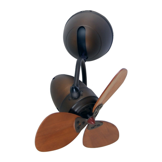
- Page 1 ASSEMBLY AND INSTALLATION MANUAL OF CEILING FAN FINO...
- Page 2 I. IMPORTANT SAFETY INSTRUCTIONS Installation must be carried out by a qualified electrician. Turn off the electrical mains at the circuit breaker/fuse box. Do not use power supply other than 220V / 50Hz. This appliance must be earthed. When mounting the fan, ensure that the safety wire is looped across the mounting bracket. The mounting bracket must be able to withhold a min.
- Page 3 II. FOR YOUR CONVENIENCE ON ASSEMBLY & INSTALLATION, PLEASE FOLLOW THIS MANUAL DESCRIPTION 1. Tools: Philips Screwdriver Slotted Screwdriver Adjustable wrench Cutter Ladder Install the power cord in accordance with the cord Check if all parts and accessories are present: Mounting Bracket Remote Control Screw Pack...
- Page 4 III. INSTALLATION INSTRUCTION ATTENTION: Do not install the fan onto the partition ceiling or chapped wall. The ceiling fan must be mounted at a min. height of 7.5ft/2.3m of clearance from the floor. 2.3m Floor The mounting bracket must be securely fastened to a structural ceiling member. NOTE: Make sure all screws are tightened.
- Page 5 Put the downrod through the canopy opening, as shown in the diagram. Ball Canopy Downrod Insert wire and safety wire through the downrod set. Fit one end of the downrod, with no ball attached, to the top portion of the “U” tube. Put the washer through the downrod screw. Then put the washer and spring washer through the downrod screw at the other end.
- Page 6 Adjust the angle into proper position, then tighten the screws. SET SCREW 0° SET SCREW SET SCREW Check if the mounting bracket is properly and securely installed, then place the assembled fan onto the mounting bracket. Mounting Bracket Downrod Set Canopy...
- Page 7 The ball at the top of the downrod allows the fan to face six directions, confirm a direction before placing the ball onto the mounting bracket. As shown in the diagram below. Mounting Bracket Tighten the two downrod set screws to make sure the fan run stably. Then, install downrod (ball part) into mounting bracket opening that already securely fastened to...
- Page 8 IV. INSTALLATION INSTRUCTIONS FOR CEILING FAN REMOTE CONTROL A. IMPORTANT POINTS: Please read this manual and keep it for future use. Turn off the electrical mains at the circuit breaker/fuse box. Please note that all wiring connections should be done by a qualified electrician. This unit is to be used in an AC220V / 50Hz supply zone only.
- Page 9 V. CODE SWITCH SETTING These DIP code can be pushed upward and downward to change the setting. Both of these remote control components (receiver and transmitter) have a set of four switches that need to have the same settings. (The total combination becomes 16 frequency codes).
- Page 10 VI. WIRING FOR CEILING FAN INSTALLATION NOTE: a.) Incorrect wire connection may damage this fan and receiver. b.) Do not attempt to shorten the receiver’s antenna wire. A typical ceiling fan remote control is wired as shown in this wiring diagram. (Fig. 1) Make sure that the wire of brown/blue/orange is connected.
- Page 11 VII. FUSE REPLACEMENT VII. FUSE REPLACEMENT Push both side of the fuse capsule towards each other and twist it to open the fuse capsule. Remove the damaged 5A glass fuse from the capsule then replace a new 5A glass fuse. To close the fuse capsule aline the latch and groove then push in and twist to lock the fuse capsule.
- Page 12 VIII. TROUBLE SHOOTING PROBLEM A: FAN WILL NOT START REMEDIES: Check fuse or circuit breaker and replace if necessary. Turn off electrical power, check all wire connections. Check to make sure the dip switches from the transmitter and receiver are set on the same frequency. PROBLEM B: FAN EXCESSIVELY NOISY REMEDIES: Check that all screws in fan assembly are tight and properly seated.
- Page 13 B40517B KE...
Need help?
Do you have a question about the FINO and is the answer not in the manual?
Questions and answers