Advertisement
Advertisement
Table of Contents

Related Manuals for Vento URAGANO


Summary of Contents for Vento URAGANO
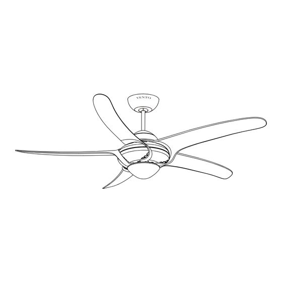
- Page 1 ASSEMBLY AND INSTALLATION MANUAL OF CEILING FAN URAGANO B40492E ALL-ENGLISH...
-
Page 3: Troubleshooting
VIII. TROUBLE SHOOTING I. IMPORTANT SAFETY INSTRUCTIONS PROBLEM A: FAN WILL NOT START Installation must be carried out by a qualified electrician. REMEDIES: Turn off the electrical mains at the circuit breaker/fuse box. Check fuse or circuit breaker and replace if necessary. Do not use power supply other than 220V~240V / 50Hz, 60Hz. -
Page 4: Fuse Replacement
II. FOR YOUR CONVENIENCE ON ASSEMBLY & INSTALLATION, VII. FUSE REPLACEMENT PLEASE FOLLOW THIS MANUAL DESCRIPTION Push both side of the fuse capsule towards each other and twist it to open the fuse capsule. Remove the damaged 5A glass fuse from the capsule then replace a new 1. -
Page 5: Installation Instruction
VI. WIRING FOR CEILING FAN INSTALLATION III. INSTALLATION INSTRUCTION NOTE: a.) Incorrect wire connection may damage this fan and receiver. ATTENTION: Do not install the fan onto the partition ceiling or chapped wall. b.) Do not attempt to shorten the receiver’s antenna wire. A typical ceiling fan remote control is wired as shown in this wiring diagram. - Page 6 The mounting bracket must be securely fastened to a structural ceiling member. V. CODE SWITCH SETTING NOTE: a.) Please choose one of the following ways to install the mounting bracket. These DIP code can be pushed upward and downward to change the setting. b.) Make sure all screws are tightened.
- Page 7 IV. INSTALLATION INSTRUCTIONS FOR CEILING Loosen 2 screws at the yoke of the motor assembly. Slide the canopy into the downrod. Thread the power leads from the fan through the canopy, decorative cover and downrod FAN REMOTE CONTROL (take extra care not to pull power wires damage). Set downrod into yoke and rotate A.
- Page 8 8. Insert the receiver into the mounting bracket (see the illustration on page 9-11 ). Loosen SUMMER MODE: The reversible switch is in the “left” position to make the airflow will the screws from the mounting bracket, uphold the canopy to cover the mounting bracket, be directed downwards for cooling in summer.
Need help?
Do you have a question about the URAGANO and is the answer not in the manual?
Questions and answers