
Related Manuals for Utax CLP 3521


Summary of Contents for Utax CLP 3521
- Page 1 Service Manual Color Printer CLP 3521 CLP 3621 CLP 3626 Rev.: 2.0 Date: 21-09-2010 2HNSM062...
- Page 2 Service Manual Color Printer CLP 4521 CLP 4621 CLP 4626 Rev.: 2.0 Date: 21-09-2010 2HNSM062...
- Page 3 CAUTION RISK OF EXPLOSION IF BATTERY IS REPLACED BY AN INCORRECT TYPE. DISPOSE OF USED BATTERIES ACCORDING TO THE INSTRUCTIONS. It may be illegal to dispose of this battery into the municipal waste stream. Check with your local solid waste officials for details in your area for proper disposal. ATTENTION IL Y A UN RISQUE D’EXPLOSION SI LA BATTERIE EST REMPLACEE PAR UN MODELE DE TYPE INCORRECT.
-
Page 4: Revision History
Revision history Revision Date Replaced pages Remarks March 5, 2009 1-2-2, 1-2-3, 1-2-4, 1-3-1, 1-3-2, 1-3-3, 1-3-4, 1-3-5, 1-3-6, 1-3-7, 1-3-9, 1-3-10, 1-3-14, 1-3-15, 1-3-16, 1-3-17, 1-3-18, 1-4-3, 1-4-4, 1-4-8, 1-4-9, 1-4-10, 1-4-11 1-4-12, 1-4-13, 1-4-14, 1-4-15, 1-4-16, 1-4-17, 1-4-18, 1-4-19, 1-4-20, 1-5-3, 1-5-32, 1-5-34, 1-5-41, 1-6-1,1-6-2, 1-6-6, 2-2-3, 2-2-4, 2-4-2, 2-4-2 December 11, 2009... - Page 5 This page is intentionally left blank.
-
Page 6: Safety Precautions
Safety precautions This booklet provides safety warnings and precautions for our service personnel to ensure the safety of their customers, their machines as well as themselves during maintenance activities. Service personnel are advised to read this booklet carefully to familiarize themselves with the warnings and precautions described here before engaging in maintenance activities. - Page 7 Safety warnings and precautions Various symbols are used to protect our service personnel and customers from physical danger and to prevent damage to their property. These symbols are described below: DANGER: High risk of serious bodily injury or death may result from insufficient attention to or incorrect compliance with warning messages using this symbol.
-
Page 8: Installation Precautions
1.Installation Precautions WARNING • Do not use a power supply with a voltage other than that specified. Avoid multiple connections to one outlet: they may cause fire or electric shock. When using an extension cable, always check that it is adequate for the rated current....................•... -
Page 9: Specifications 1
2.Precautions for Maintenance WARNING • Always remove the power plug from the wall outlet before starting machine disassembly....• Always follow the procedures for maintenance described in the service manual and other related brochures............................• Under no circumstances attempt to bypass or disable safety features including safety mechanisms and protective circuits. - Page 10 • Do not remove the ozone filter, if any, from the copier except for routine replacement..... • Do not pull on the AC power cord or connector wires on high-voltage components when removing them; always hold the plug itself...................... •...
- Page 11 This page is intentionally left blank.
- Page 12 2HL/2HM/2HN CONTENTS 1-1 Specifications 1-1-1 Specifications............................1-1-1 1-1-2 Parts names............................1-1-7 (1) Overall ...............................1-1-7 (2) Operation panel..........................1-1-9 1-1-3 Machine cross section ..........................1-1-10 1-2 Installation 1-2-1 Installation environment ..........................1-2-1 1-2-2 Unpacking ...............................1-2-2 (1) Unpacking ............................1-2-2 (2) Removing the tape ..........................1-2-4 1-2-3 Installing the expansion memory modules (option).................1-2-5 1-2-4 Installing the memory card (option)......................1-2-6 1-2-5 Installing the hard disk (option for 26/28 ppm [500-sheet] model only) ..........1-2-7 1-3 Maintenance Mode...
- Page 13 2HL/2HM/2HN 1-5-3 Paper feed section ..........................1-5-8 (1) Detaching and refitting the paper feed roller assembly (paper feed roller and pickup roller) ....1-5-8 (2) Detaching and refitting the retard roller ...................1-5-10 (3) Detaching and refitting the MP paper feed roller................1-5-12 1-5-4 Developing section..........................1-5-13 (1) Detaching and refitting the developing unit ..................1-5-13 1-5-5 Drum section............................1-5-15 (1) Detaching and refitting the drum unit ....................1-5-15...
- Page 14 2HL/2HM/2HN 2-4 Appendixes 2-4-1 Appendixes .............................2-4-1 (1) Wiring diagram ..........................2-4-1 (2) Repetitive defects gauge........................2-4-3 (3) Maintenance parts list ........................2-4-4...
- Page 15 2HL/2HM/2HN This page is intentionally left blank.
-
Page 16: Specifications
2HL/2HM/2HN 1-1 Specifications 1-1-1 Specifications 26/28 ppm (500-sheet) model Type ..........Desktop Printing method....... Electrophotographic four color (CMYK) printing using tandem (4) drum system Paper weight........Cassette: 60 to 120 g/m MP tray: 60 to 220 g/m Paper types* ........Cassette: Plain, preprinted, bond, recycled, rough, letterhead, color, prepunched, high quality, and custom MP tray:... - Page 17 2HL/2HM/2HN Resolution........600 dpi Operating systems......Microsoft Windows 2000/XP/Vista, Windows Server 2003 Apple Macintosh OS X Interface.......... USB: Hi-Speed USB Network: 10 BASE-T/100 BASE-TX KUIO-LV slot Option: Hard disk Memory card slot ......1 (CompactFlash, 4 GB or less) Margin..........4 mm (left, right, top and bottom) °...
- Page 18 2HL/2HM/2HN 21/23 ppm (500-sheet) model Type ..........Desktop Printing method....... Electrophotographic four color (CMYK) printing using tandem (4) drum system Paper weight........Cassette: 60 to 120 g/m MP tray: 60 to 220 g/m Paper types* ........Cassette: Plain, preprinted, bond, recycled, rough, letterhead, color, prepunched, high quality, and custom MP tray: Plain, transparency, preprinted, labels, bond, recycled, vellum, rough, letterhead,...
- Page 19 2HL/2HM/2HN Resolution........600 dpi Operating systems......Microsoft Windows 2000/XP/Vista, Windows Server 2003 Apple Macintosh OS X Interface.......... USB: Hi-Speed USB Network: 10 BASE-T/100 BASE-TX KUIO-LV slot Memory card slot ......1 (CompactFlash, 4 GB or less) Margin..........4 mm (left, right, top and bottom) °...
- Page 20 2HL/2HM/2HN 21/23 ppm (250-sheet) model Type ..........Desktop Printing method....... Electrophotographic four color (CMYK) printing using tandem (4) drum system Paper weight........Cassette: 60 to 120 g/m MP tray: 60 to 220 g/m Paper types* ........Cassette: Plain, preprinted, bond, recycled, rough, letterhead, color, prepunched, high quality, and custom MP tray: Plain, transparency, preprinted, labels, bond, recycled, vellum, rough, letterhead,...
- Page 21 2HL/2HM/2HN Resolution........600 dpi Operating systems......Microsoft Windows 2000/XP/Vista, Windows Server 2003 Apple Macintosh OS X Interface.......... USB: Hi-Speed USB Network: 10 BASE-T/100 BASE-TX KUIO-LV slot Memory card slot ......1 (CompactFlash, 4 GB or less) Margin..........4 mm (left, right, top and bottom) °...
-
Page 22: Parts Names 1
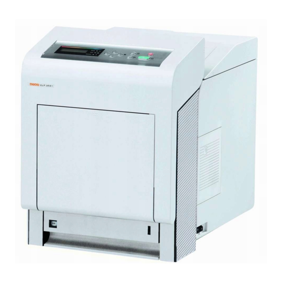
2HL/2HM/2HN 1-1-2 Parts names (1) Overall 21/23 ppm (500-sheet) model and 26/28 ppm (500-sheet) model 21/23 ppm (500-sheet) model 26/28 ppm (500-sheet) model Figure 1-1-1 Operation panel Waste toner box 17. Envelope switch Front cover 10. Main charger units 18. USB memory slot Top cover (Top tray) 11. - Page 23 2HL/2HM/2HN 21/23 ppm (250-sheet) model Figure 1-1-2 Operation panel Waste toner box 17. Envelope switch Front cover 10. Main charger units 18. USB memory slot Top cover (Top tray) 11. Toner container M 19. USB interface Paper stopper 12. Toner container C 20.
- Page 24 2HL/2HM/2HN (2) Operation panel 2 3 5 Figure 1-1-3 Message display Ready indicator Data indicator Attention indicator Arrow keys MENU key OK key GO key CANCEL key 1-1-9...
- Page 25 2HL/2HM/2HN 1-1-3 Machine cross section 21/23 ppm (500-sheet) model and 26/28 ppm (500-sheet) model 21/23 ppm (500-sheet) model Light path Paper path Paper path (optional) Figure 1-1-4 Cassette 14. Developing unit M MP tray 15. Developing unit C Duplex unit B 16.
- Page 26 2HL/2HM/2HN 21/23 ppm (250-sheet) model Light path Paper path Paper path (optional) Figure 1-1-5 Cassette 14. Developing unit M MP tray 15. Developing unit C Duplex unit B 16. Developing unit Y Drum unit M 17. Developing unit K Drum unit C 18.
- Page 27 2HL/2HM/2HN This page is intentionally left blank. 1-1-12...
- Page 28 2HL/2HM/2HN 1-2 Installation 1-2-1 Installation environment ° ° Temperature: 10 to 32.5 C/50 to 90.5 Humidity: 15 to 80%RH Power supply: 120 V AC, 220 - 240 V AC ± ± Power source frequency: 50 Hz 0.3%/60 Hz 0.3% Installation location Avoid direct sunlight or bright lighting.
- Page 29 2HL/2HM/2HN-1 1-2-2 Unpacking (1) Unpacking 220-240 V AC model 21/23 ppm (250-sheet) model 21/23 ppm (500-sheet) model 26/28 ppm (500-sheet) model 240 V AC model 230 V AC model Figure 1-2-2 220-240 V AC model Printer 10. Bottom front/side pad 17.
- Page 30 2HL/2HM/2HN-1 120 V AC model 26/28 ppm (500-sheet) model 21/23 ppm (500-sheet) model 21/23 ppm 21/23 ppm (250-sheet) (250-sheet) model model 21/23 ppm (500-sheet) model 26/28 ppm (500-sheet) model Figure 1-2-3 120 V AC model 12. Machine cover 600 × 600 × 900 Printer Toner container (Yellow) 13.
- Page 31 2HL/2HM/2HN-1 (2) Removing the tape <Procedure> 1. Remove the tape-A. 1. Remove two tapes-B and then remove the installation guide and desiccating agent. Tape-B Installation guide Tape-B Desiccating agent Tape-A Figure 1-2-4 1-2-4...
- Page 32 2HL/2HM/2HN 1-2-3 Installing the expansion memory modules (option) <Procedure> 1. Turn off printer power switch. Caution: Do not insert or remove expansion memory modules while printer power is on. Doing so may cause damage to the printer and the expansion memory modules. 2.
- Page 33 2HL/2HM/2HN 1-2-4 Installing the memory card (option) <Procedure> 1. Turn off printer power switch. Caution: Do not insert or remove memory card while printer power is on. Doing so may cause damage to the printer and the memory card. 2. Remove the two screws and then remove the main PWB.
- Page 34 2HL/2HM/2HN 1-2-5 Installing the hard disk (option for 26/28 ppm [500-sheet] model only) <Procedure> 1. Turn off printer power switch. Caution: Do not insert or remove hard disk unit while printer power is on. Doing so may cause damage to the printer and the hard disk.
- Page 35 2HL/2HM/2HN This page is intentionally left blank. 1-2-8...
-
Page 36: Hl/2Hm/2Hn
2HL/2HM/2HN-1 1-3 Maintenance Mode 1-3-1 Maintenance mode The printer is equipped with a maintenance function which can be used to maintain and service the machine. (1) Executing a maintenance item Message display Ready 1. Press the MENU key. Report Print >... -
Page 37: Paper Feeder
2HL/2HM/2HN-1 (2) Service mode Service items Description Printing a status page for service purpose Description Prints a status page for service purpose. The status page includes various printing settings >>Print Status Page and service cumulative. Purpose To acquire the current printing environmental parameters and cumulative information. Procedure Enter the service mode [>>Print Status Page]. -
Page 38: Paper Feeder
2HL/2HM/2HN-1 Service items Description Detail of service status page (1) Items Description Firmware version Engine software version Engine boot version Main ROM version Panel mask version Used memory Local time zone Presence or absence of Installed: Paper feeder (Normal) the optional paper feeder Installed (Multi purpose): Multi purpose feeder Not Installed: Absence Presence or absence of... -
Page 39: Service Status Page
2HL/2HM/2HN-1 Service items Description Service status page (2) Service Status Page Printer Firmware Version 2HN_3000.000.040 2009.01.27 [XXXXXXXX] [XXXXXXXX] [XXXXXXXX] [XXXXXXXX] Engine Information NVRAM Version XXXXXXXXXXX MAC Address 00:00:00:00:00:00 100/100 0/0/0/0/0/0/0 0/0/0/0/0/0/0 0/0/0/0/0/0/0/0/ 0000000/0000000/0000000/0000000/0000000/0000000/0000000/0000000/ 0000000/0000000/0000000/0000000/0000000/0000000/0000000/0000000/0000000/0000000/ F00/U00/0/0/0/0/30/30/70/70/00/00/ABCDE/ 0000/0000/0000/0000/0000/0000/0000/0000/0000/0000/0000/0000/0000/0000/0000/ 0000/0000/0000/0000/0000/0000/0000/0000/0000/0000/ 0203040508090A0B0C0D0F101112131415161718191A1B1C1D1E1F202122235E 0000/0100/0500/1000/0000/0100/0500/1000/0000/0100/0500/1000/0000/0100/0500/1000/ 0000/0100/0500/1000/0000/0100/0500/1000/0000/0100/0500/1000/0000/0100/0500/1000/ 000000000000000000000000000000000000000000000000000000000000000000000000000000000000000000000000/ 000000000000000000000000000000000000000000000000/ 0000000000000000000000000000000000000000/0000000000/... - Page 40 2HL/2HM/2HN-1 Service items Description Detail of service status page (2) Items Description NVRAM version _ 1F3 1225 _ 1F3 1225 (a) (b) (c) (d) (e) a) Consistency of the present software version and the database _ (underscore): OK * (Asterisk): NG (b) Database version (c) The oldest time stamp of database version (d) Consistency of the present software version and the ME firmware ver-...
- Page 41 2HL/2HM/2HN-1 Service items Description Items Description Billing counting timing Temperature (machine inside) Temperature (machine out- side) Relative temperature (machine outside) Absolute temperature (machine outside) LSU information LSU2 information Fixed asset number Media type attributes Weight settings Fuser settings 1 to 28 (Not used: 18, 19, 0: Light 0: High 1: Normal 1...
- Page 42 2HL/2HM/2HN-1 Service items Description Items Description Optional font version Optional table version Optional message version WEB option version Color table version Developing unit serial number Black/Cyan/Magenta/Yellow/ Drum unit ID Black/Cyan/Magenta/Yellow/ Drum unit serial number Black/Cyan/Magenta/Yellow/ NOTE: Code conversion 1-3-7...
- Page 43 2HL/2HM/2HN Service items Description Printing a status page for network Description On the status page for network, detailed network setting information is printed. >>Print Network Status Page Procedure 1. Enter the service mode [>>Print Network Status Page]. 2. Press the OK key. [>>Print Network Status Page?] will be displayed. 3.
- Page 44 2HL/2HM/2HN-1 Service items Description Write data (USB memory data write) Description >>Write Data To write data into a USB memory. Procedure Install the USB memory before attempting to write data. 1. Enter the service mode [>>Write Data]. 2. Press the OK key. [>>Write Data?] will be displayed. 3.
- Page 45 2HL/2HM/2HN-1 Service items Description Entering initial value (6-digit data) for replacing the developing unit Description After replacing the developing unit, enter the initial value (6-digit data) assigned on a label >>DEV-SET attached to the package or developing unit. Procedure Enter the service mode [>>DEV-SET]. Press the OK key.
- Page 46 2HL/2HM/2HN Service items Description Developer refreshing Description The laser output of the image data for developer refreshing is carried out, and operation to >>DEV-CLN exposure, developing, and primary transfer is performed by 10 pages. (Paper is not fed) Purpose To perform cleaning when faulty images occur and a line appears longitudinally. Procedure 1.
- Page 47 2HL/2HM/2HN Service items Description Drum surface refreshing Description Rotates the drum approximately 2 minutes with toner lightly on the overall drum using the >>Drum high-voltage output control of the engine PWB. The cleaning blade in the drum unit scrapes toner off the drum surface to clean it. Purpose To clean the drum surface when image failure occurs due to the drum.
- Page 48 2HL/2HM/2HN (3) Printing a event log (EVENT LOG) Service items Description Printing an event log Printing an event log (EVENT LOG) (EVENT LOG) Description Prints a history list of occurrences of paper jam, self-diagnostics, toner replacements, etc. Purpose To allow machine malfunction analysis based on the frequency of paper misfeeds, self diag- nostic errors and replacements.
-
Page 49: Event Log
2HL/2HM/2HN-1 Service items Description Detail of event log Event Log Printer Firmware Version 2HN_3000.000.000 2009.01.27 [XXXXXXXX] [XXXXXXXX] [XXXXXXXX] [XXXXXXXX] Paper Jam Log Service Call Log Count. Event Descriptions Count. Service Code 9999999 10. 01. 88. 01. 01 1111111 00. 0000 8888888 10. - Page 50 2HL/2HM/2HN-1 Service items Description Items Description Paper Count. Event cont. Remembers 1 to 16 of occurrence. The total page Log code (2 digit, hexadecimal, 5 cate- If the occurrence of the previous count at the time gories) paper jam is less than 16, all of the of the paper paper jams are logged.
- Page 51 2HL/2HM/2HN-1 Service items Description Items Description Paper Jam Log Jam location cont. 26/28 ppm (500-sheet) model 21/23 ppm (500-sheet) model Paper jam location MP tray Cassette 1 (printer) Paper feeder 1 Paper feeder 2 Paper feeder 3 Printer inside Paper exit section Duplex section Sensors Registration sensor...
- Page 52 2HL/2HM/2HN-1 Service items Description Items Description Paper Jam Log (b) Detail of paper source (Hexadecimal) cont. 00: MP tray 06: - 01: Paper cassette 1 (printer) 07: Duplex unit 02: Paper cassette 2 (paper feeder 1) 08: Bulk paper feeder 03: Paper cassette 3 (paper feeder 2) 09: Envelope feeder 04: Paper cassette 4 (paper feeder 3)
- Page 53 2HL/2HM/2HN-1 Service items Description Items Description Maintenance Count. Item Remembers 1 to 8 of The total page count at the Code of maintenance replacing occurrence of replace- time of the replacement of item (1 byte, 2 categories) NOTE: ment. If the occurrence of the toner container.
- Page 54 2HL/2HM/2HN 1-4 Troubleshooting 1-4-1 Paper misfeed detection (1) Paper misfeed indication If the paper jammed in the paper transport system, or no paper sheets were fed at all, the “Paper jam” message appears and the location of the paper jam (the component where the paper jam has occurred) is also indicated. The printer auto- matically goes off-line when this message is displayed.
- Page 55 2HL/2HM/2HN 1-4-2 Self-diagnostic function (1) Self-diagnostic function This printer is equipped with self-diagnostic function. When a problem is detected, the printer stops printing and display an error message on the operation panel. An error message consists of a message prompting a contact to service personnel, total print count, and a four-digit error code indicating the type of the error.
-
Page 56: Defective Pf Main Replace The Pf Main Pwb (Refer To The Ser
2HL/2HM/2HN-1 (2) Self diagnostic codes Remarks Code Contents Causes Check procedures/corrective measures 0100 Backup memory read/write error Defective main Replace the main PWB (See page 1-5-29). PWB. 0110 Backup memory data error Defective main Replace the main PWB (See page 1-5-29). PWB. - Page 57 2HL/2HM/2HN-1 Remarks Code Contents Causes Check procedures/corrective measures 0640 Hard disk error Defective hard Replace the hard disk (See page 1-2-7). disk. Defective main Replace the main PWB (See page 1-5-29). PWB. 0930 I2C bus error Defective RFID. Replace the RFID. Defective drum Replace the drum unit (See page 1-5-15).
- Page 58 2HL/2HM/2HN Remarks Code Contents Causes Check procedures/corrective measures 1500 PF warm air heater (upper blower) The inlet of upper Check visually and remove it, if any (Refer 1520 high temperature error* blower assembly is to the service manual for the paper feeder). 1540 (Option paper feeder) blocked by paper...
-
Page 59: Installed Incor- And Remedy If Necessary (Refer To The Ser
2HL/2HM/2HN Remarks Code Contents Causes Check procedures/corrective measures 1600 PF warm air heater (upper blower) low Defective harness Reinsert the connector. Also check for conti- 1620 temperature error* between PF warm nuity within the connector harness. If none, 1640 (Option paper feeder) air heater 2 and PF remedy or replace the harness. - Page 60 2HL/2HM/2HN Remarks Code Contents Causes Check procedures/corrective measures 1610 PF warm air heater (side blower) Defective harness Reinsert the connector. Also check for conti- 1630 error* between PF warm nuity within the connector harness. If none, 1650 (Option paper feeder) air heater 1 and PF remedy or replace the harness.
- Page 61 2HL/2HM/2HN-1 Remarks Code Contents Causes Check procedures/corrective measures 2102 Developing motor MCY error Defective harness Reinsert the connector. Also check for conti- The ready signal cannot be detected between develop- nuity within the connector harness. If none, within 5 seconds after the developing ing motor MCY and remedy or replace the harness.
-
Page 62: Defective Pf Main Replace The Pf Main Pwb (Refer To The Ser
2HL/2HM/2HN-1 Remarks Code Contents Causes Check procedures/corrective measures 2610 PF paper feed motor error Defective harness Reinsert the connector. Also check for conti- 2620 (Option paper feeder) between PF paper nuity within the connector harness. If none, 2630 The PF paper feed motor of paper feeder feed motor and PF remedy or replace the harness. - Page 63 2HL/2HM/2HN-1 Remarks Code Contents Causes Check procedures/corrective measures 4002 Polygon motor MC error Defective harness Reinsert the connector. Also check for conti- The polygon motor MC ready input is not between polygon nuity within the connector harness. If none, given for 10 seconds during the polygon motor MC and remedy or replace the harness.
-
Page 64: Defective Main Replace The Main Pwb (See Page 1
2HL/2HM/2HN-1 Remarks Code Contents Causes Check procedures/corrective measures 4204 Laser output error (Yellow) Defective harness Reinsert the connector. Also check for conti- The pin photo signal (PDN) is not output between APC nuity within the connector harness. If none, from PD PWB Y for one second while PWB Y and engine remedy or replace the harness. -
Page 65: Defective Engine Replace The Engine Pwb (See Page 1-5 Pwb
2HL/2HM/2HN-1 Remarks Code Contents Causes Check procedures/corrective measures 5301 Broken eraser lamp K wire Defective harness Reinsert the connector. Also check for conti- When the eraser lamp K is driven, the between drum unit nuity within the connector harness. If none, eraser lamp K over-current detection sig- K and drum relay remedy or replace the harness. - Page 66 2HL/2HM/2HN-1 Remarks Code Contents Causes Check procedures/corrective measures 5304 Broken eraser lamp Y wire Defective harness Reinsert the connector. Also check for conti- When the eraser lamp Y is driven, the between drum unit nuity within the connector harness. If none, eraser lamp Y over-current detection sig- Y and drum relay remedy or replace the harness.
- Page 67 2HL/2HM/2HN-1 Remarks Code Contents Causes Check procedures/corrective measures 6020 Abnormally high temperature fuser Shorted fuser ther- Replace the fuser unit (See page 1-5-26). heater lamp mistor. The fuser thermistor detects a tempera- Defective engine Replace the engine PWB (See page 1-5- °...
- Page 68 2HL/2HM/2HN-1 Remarks Code Contents Causes Check procedures/corrective measures 7001 Toner motor K error Defective harness Reinsert the connector. Also check for conti- When the toner motor K is driven, the between toner nuity within the connector harness. If none, toner motor K over-current detection sig- motor K and remedy or replace the harness.
- Page 69 2HL/2HM/2HN-1 Remarks Code Contents Causes Check procedures/corrective measures 7004 Toner motor Y error Defective harness Reinsert the connector. Also check for conti- When the toner motor Y is driven, the between toner nuity within the connector harness. If none, toner motor Y over-current detection sig- motor Y and remedy or replace the harness.
- Page 70 2HL/2HM/2HN-1 Remarks Code Contents Causes Check procedures/corrective measures 7403 Developing unit M non-installing error Faulty connection Check the installation of the developing unit No density detection signal is output of the connector M and drum relay PWB and reinstall them if from toner sensor M in developing unit between the devel- necessary (See page 1-5-13).
- Page 71 2HL/2HM/2HN-1 Remarks Code Contents Causes Check procedures/corrective measures 7412 Drum unit C non-installing error Faulty connection Check the installation of the drum unit C and The EEPROM of drum PWB C does not of the connector drum relay PWB and reinstall them if neces- communicate normally.
- Page 72 2HL/2HM/2HN-2 Remarks Code Contents Causes Check procedures/corrective measures 7414 Drum unit Y non-installing error Faulty connection Check the installation of the drum unit Y and The EEPROM of drum PWB Y does not of the connector drum relay PWB and reinstall them if neces- communicate normally.
- Page 73 2HL/2HM/2HN-2 Remarks Code Contents Causes Check procedures/corrective measures F030 Main PWB general failure Defective main Turn the power switch off/on to restart the PWB. printer. If the error is not resolved, replace main PWB (See page 1-5-29). F040 Main PWB - Engine PWB communica- Faulty connection Check the installation of the main PWB and tion error...
-
Page 74: Image Formation Problems
2HL/2HM/2HN 1-4-3 Image formation problems (1)No image appears (2)No image appears (3)A specific color is (4)The back side gets (5)Image is too light. (entirely white). (entirely black). printed solid. dirty. See page 1-4-22 See page 1-4-23 See page 1-4-23 See page 1-4-23 See page 1-4-24 (6)The background is (7)White streaks are... - Page 75 2HL/2HM/2HN (1) No image appears (entirely white). Print example Causes Check procedures/corrective measures No trans- Defective harness Reinsert the connector. Also check for continuity within the between high voltage connector harness. If none, remedy or replace the harness. charging. PWB and engine PWB (YC16), or improper con- nector insertion.
- Page 76 2HL/2HM/2HN (2) No image appears (entirely black). Print example Causes Check procedures/corrective measures No main Defective harness Reinsert the connector. Also check for continuity within the charging. between high voltage connector harness. If none, remedy or replace the harness. PWB and engine PWB (YC16), or improper con- nector insertion.
- Page 77 2HL/2HM/2HN (5) Image is too light. Print example Causes Check procedures/corrective measures Defec- Defective developing unit. Replace the developing unit for the color that causes an error. tive Defective high voltage Replace the high voltage PWB (See page 1-5-35). develop- PWB.
- Page 78 2HL/2HM/2HN (7) White streaks are printed vertically. Print example Causes Check procedures/corrective measures Foreign object in one of the develop- Check the image by using the test print of service mode. If the ing units. white line appears on a particular page, replace the developer for that color (See page 1-5-13).
- Page 79 2HL/2HM/2HN (11) The leading edge of image begins to print too early or too late. Print example Causes Check procedures/corrective measures Paper feed clutch or registration Check the installation of the clutch. If it operates incorrectly, clutch operating incorrectly. replace it. (12) Paper is wrinkled.
- Page 80 2HL/2HM/2HN (15) Fusing is loose. Print example Causes Check procedures/corrective measures Wrong types of paper. Check if the paper meets specifications, replace paper. Flawed heat roller or press roller. Replace the heat roller and press roller (See page 1-5-26). (16) Colors are printed offset to each other. Print example Causes Check procedures/corrective measures...
-
Page 81: Electric Problems
2HL/2HM/2HN 1-4-4 Electric problems Problem Causes Check procedures/corrective measures (1)The machine does The power cord is not Check the contact between the power plug and the outlet. not operate when the plugged in properly. power switch is No electricity at the power Measure the input voltage. - Page 82 2HL/2HM/2HN Problem Causes Check procedures/corrective measures (6)Main charging is Defective harness or Reinsert the connector. Also check for continuity within the con- not performed. improper connector inser- nector harness. If none, remedy or replace the high voltage PWB tion. (See page 1-5-35). High voltage PWB - Engine PWB (YC16) Defective main charger unit Replace the main charger unit (See page 1-5-16).
- Page 83 2HL/2HM/2HN Problem Causes Check procedures/corrective measures (13)The message Defective harness or Reinsert the connector. Also check for continuity within the con- requesting front improper connector inser- nector harness. If none, remedy or replace the harness. cover to be closed is tion.
-
Page 84: Mechanical Problems
2HL/2HM/2HN 1-4-5 Mechanical problems Problem Causes/check procedures Corrective measures (1)No primary paper Check if the surfaces of the paper feed roller, Clean with isopropyl alcohol. feed. MP paper feed roller are dirty with paper pow- der. Check if the paper feed roller, MP paper feed Check visually and replace any deformed roller are deformed. - Page 85 2HL/2HM/2HN This page is intentionally left blank. 1-4-32...
- Page 86 2HL/2HM/2HN 1-5 Assembly and Disassembly 1-5-1 Precautions for assembly and disassembly (1) Precautions Be sure to turn the power switch off and disconnect the power plug before starting disassembly. When handling PWBs, do not touch connectors with bare hands or damage the PWB. Use only the specified parts to replace the fuser unit thermostat.
- Page 87 2HL/2HM/2HN-2 (4) How to tell a genuine Kyocera Mita toner container As a means of brand protection, the Kyocera Mita toner container utilizes an optical security technology to enable visual validation. A validation viewer is required to accomplish this. Hold the validation viewer over the left side part of the brand protection seal on the toner container. Through each window of the validation viewer, the left side part of the seal should be seen as follows: A black-colored band when seen through the left side window A shiny or gold-colored band when seen through the right side window...
- Page 88 2HL/2HM/2HN-1 1-5-2 Outer covers (1) Detaching and refitting the left rear cover, left upper cover and left front cover Procedure 1. Open the left cover. 2. Remove the waste toner box. 3. Remove two screws. Left cover Screw Screw Waste toner box Figure 1-5-3 1-5-3...
- Page 89 2HL/2HM/2HN 4. Open the top cover. 5. Release the five hooks and then remove the left rear cover. Top cover Hooks Left rear cover 26/28 ppm (500-sheet) model 21/23 ppm (500-sheet) model Left rear cover 21/23 ppm (250-sheet) model Hooks Left rear cover Figure 1-5-4 1-5-4...
- Page 90 2HL/2HM/2HN 6. Open the front cover. 7. Remove the screw and then remove the left upper cover. Left upper cover 8. Slide the left front cover upward and then remove it. Screw Left front cover Front cover 26/28 ppm (500-sheet) model 21/23 ppm (500-sheet) model Left front cover 21/23 ppm (250-sheet) model...
- Page 91 2HL/2HM/2HN (2) Detaching and refitting the right rear cover, right upper cover and right front cover Procedure 1. Open the top cover. 2. Open the right cover. 3. Remove the two screws. Hooks 4. Release the five hooks and then remove the right rear cover.
- Page 92 2HL/2HM/2HN 5. Open the front cover. 6. Remove the two screws and then remove the right upper cover. 7. Slide the right front cover and then remove Screws Right upper cover Right front cover Front cover 26/28 ppm (500-sheet) model 21/23 ppm (500-sheet) model Right front cover 21/23 ppm (250-sheet) model...
- Page 93 2HL/2HM/2HN 1-5-3 Paper feed section (1) Detaching and refitting the paper feed roller assembly (paper feed roller and pickup roller) Procedure 1. Remove the cassette. 21/23 ppm (250-sheet) model Cassette 26/28 ppm (500-sheet) model Cassette 21/23 ppm (500-sheet) model Figure 1-5-8 1-5-8...
- Page 94 2HL/2HM/2HN 2. While pressing lever A and then slide the feed roller pin. 3. While pressing the lever B and then remove the paper feed roller assembly. Feed roller pin Lever A Lever B Paper feed roller assembly Figure 1-5-9 4.
- Page 95 2HL/2HM/2HN (2) Detaching and refitting the retard roller Procedure 1. Remove the cassette (See page 1-5-8). 21/23 ppm (250-sheet) model Retard guide 2. Push the bottom plate down until it locks. 21/23 ppm (500-sheet) model and 26/28 Hook ppm (500-sheet) model only. 3.
- Page 96 2HL/2HM/2HN 4. Remove the retard roller assembly. Retard guide 5. Check or replace the retard roller assembly and refit all the removed parts. Retard roller assembly Figure 1-5-12 1-5-11...
- Page 97 2HL/2HM/2HN (3) Detaching and refitting the MP paper feed roller Procedure 1. Open the front cover. 2. While releasing the hook and the slide the MPF shaft. 3. Remove the MP paper feed roller. 4. Check or replace the MP paper feed roller and refit all the removed parts.
- Page 98 2HL/2HM/2HN 1-5-4 Developing section (1) Detaching and refitting the developing unit Procedure 1. Remove the intermediate transfer unit (See page 1-5-17). 2. Remove the drum unit (M,C,Y,K) (See page 1-5-15). 3. Pinch the lever of developing unit. Lever 4. Remove the developing unit (M,C,Y,K). Developing unit Developing unit M Developing unit C...
- Page 99 2HL/2HM/2HN 5. Check or replace the developing unit and refit all the removed parts. NOTE: Remove the cap before installing the new developing unit. When reinstalling the developing unit, press it down until the lever of developing unit is engaged with the notch. New developing unit If it is difficult to engage the lever, press the unit down while rotating the gear to engage...
- Page 100 2HL/2HM/2HN 1-5-5 Drum section (1) Detaching and refitting the drum unit Procedure 1. Remove the intermediate transfer unit (See page 1-5-17). 2. Remove the drum unit (M,C,Y,K). 3. Check or replace the drum unit and refit all the removed parts. Drum unit Drum unit M Drum unit C...
- Page 101 2HL/2HM/2HN (2) Detaching and refitting the main charger unit Procedure 1. Open the left cover. 2. Remove the main charger unit (M,C,Y,K). 3. Check or replace the main charger unit and Main charger Left cover refit all the removed parts. unit M Main charger unit C...
- Page 102 2HL/2HM/2HN 1-5-6 Transfer/separation section (1) Detaching and refitting the intermediate transfer unit Procedure 1. Open the top cover. 2. Remove the all toner containers (M,C,Y,K). Toner container C Toner container M Toner container Y Toner container K 21/23 ppm (250-sheet) model Toner container C Toner container M Toner container Y...
- Page 103 2HL/2HM/2HN 3. Remove the all container guides (M,C,Y,K). Container guide C Container guide Y Container guide K Container guide M Figure 1-5-19 4. Remove the two screws. Screw 5. Open the RFID holder. Screw RFID holder Figure 1-5-20 1-5-18...
- Page 104 2HL/2HM/2HN 6. Remove the intermediate transfer unit. Intermediate 7. Check or replace the intermediate transfer transfer unit unit and refit all the removed parts. Projection Projection Guide Guide Intermediate transfer unit Intermediate transfer unit Figure 1-5-21 1-5-19...
- Page 105 2HL/2HM/2HN (2) Detaching and refitting the transfer roller unit Procedure 1. Open the front cover. 2. Open the duplex unit B. 3. Release the two hooks and then remove the transfer roller unit. 4. Check or replace the transfer roller unit and Hook refit all the removed parts.
- Page 106 2HL/2HM/2HN (3) Detaching and refitting the duplex unit B Procedure 1. Remove the outer covers (See page 1-5-3). 2. Remove the power source PWB (See page 1-5-27). 3. While releasing the hook and then pull the MCH cleaning shaft MCH cleaning shaft. Hook Figure 1-5-23 4.
- Page 107 2HL/2HM/2HN 6. Remove the six screws and then remove the feed drive unit. Screw Screw Screw Screw Feed drive unit Screw Screw Figure 1-5-25 7. Remove the four connectors. YC39 YC26 YC40 Connectors Figure 1-5-26 1-5-22...
- Page 108 2HL/2HM/2HN 8. Remove the FFC. 9. Remove the screw and then remove the two grounding terminals. Screw Grounding terminals Figure 1-5-27 10. Remove the axis of the front cover left stop- per from the hole. 11. Remove the front cover. Front cover left stopper Axis...
- Page 109 2HL/2HM/2HN 12. Remove the two screws and then remove the MP paper feed lower unit. Screw MP paper feed lower unit Screw Figure 1-5-29 13. Remove the three connectors. Connector Connector Connector Figure 1-5-30 1-5-24...
- Page 110 2HL/2HM/2HN 14. Open the duplex unit B. 15. Remove the duplex unit B. 16. Check or replace the duplex unit B and refit all the removed parts. Duplex unit B Figure 1-5-31 1-5-25...
- Page 111 2HL/2HM/2HN 1-5-7 Fuser section (1) Detaching and refitting the fuser unit Procedure 1. Remove the outer covers (See page 1-5-3). 2. Remove three connectors. Connector Connector Connector Figure 1-5-32 3. Remove two screws. 4. Unhook the hook and then remove the fuser unit.
- Page 112 2HL/2HM/2HN 1-5-8 PWBs (1) Detaching and refitting the power source PWB Procedure 1. Remove the right rear cover (See page 1-5- 2. Remove the three screws and then remove the power source shield. Screw Screw Power source shield Screw Figure 1-5-34 3.
- Page 113 2HL/2HM/2HN 5. Remove the two connectors and then remove the power source PWB. 6. Check or replace the power source PWB and refit all the removed parts. Connector Connector Power source PWB Figure 1-5-36 1-5-28...
- Page 114 2HL/2HM/2HN (2) Detaching and refitting the main PWB Procedure 1. Remove the two screws. 2. Remove the main PWB. 3. Check or replace the main PWB and refit all the removed parts. Screw Main PWB Screw Figure 1-5-37 1-5-29...
- Page 115 2HL/2HM/2HN (3) Detaching and refitting the engine PWB Procedure 1. Remove the duplex unit B (See page 1-5- 2. Remove the connector. Connector Figure 1-5-38 3. Remove the seven screws and then remove the feed housing. Screw Feed housing Screw Screw Screw Screw...
- Page 116 2HL/2HM/2HN 4. Remove the connector A. 5. Remove the developing fan motor 1. 6. Remove the two connectors B. 7. Remove the FFC. Connector B Connector B Connector A Developing fan motor 1 Figure 1-5-40 8. Remove the three FFCs. 9.
- Page 117 2HL/2HM/2HN-1 10. While unlatching the latch and then remove the lever link. Lever link Lever link Latch Figure 1-5-42 11. Remove the twenty connectors. YC39 YC26 YC18 YC34 YC37 YC36 YC27 YC17 YC40 YC22 YC25 YC24 YC11 YC38 YC33 YC44 YC23 YC15 YC28...
- Page 118 2HL/2HM/2HN 12. Remove the three screws and then remove the engine PWB assembly. Screw Screw Screw Engine PWB assembly Figure 1-5-44 1-5-33...
- Page 119 2HL/2HM/2HN-1 13. Remove the two screws and then remove the engine PWB. 14. Check or replace the engine PWB and refit EEPROM all the removed parts. To replace the engine PWB, remove the EEPROM (U4) from the old engine PWB Screw and mount it to the new engine PWB.
- Page 120 2HL/2HM/2HN (4) Detaching and refitting the high voltage PWB Procedure 1. Remove the all drum units (See page 1-5- 15). 2. Remove the all developing units (See page 1-5-13). 3. Remove the engine PWB (See page 1-5- 30). 4. Remove the screw and then remove the HV terminal assembly K.
- Page 121 2HL/2HM/2HN 7. Remove six terminals. 8. Remove the TC high voltage bracket. 9. Remove the two screws. TC high voltage bracket Screw Terminal Terminal Screw Terminal Terminal Terminal Figure 1-5-48 10. Remove the screw. Screw Figure 1-5-49 1-5-36...
- Page 122 2HL/2HM/2HN 11. Remove the high voltage PWB assembly. High voltage PWB assembly Figure 1-5-50 12. Remove five screws and then remove the Screw high voltage PWB. Screw 13. Check or replace the high voltage PWB and refit all the removed parts. Screw Screw Screw...
- Page 123 2HL/2HM/2HN 1-5-9 Others (1) Detaching and refitting the laser scanner unit Procedure 1. Remove the all drum units (See page 1-5- 15). 2. Remove the all developing units (See page 1-5-13). 3. Remove the two connectors. 4. Remove the wires form the three clamps. Clamp Wire Clamp...
- Page 124 2HL/2HM/2HN 6. Remove the each three screws and then remove the laser scanner units (MC,YK). Laser scanner unit MC 7. Check or replace the laser scanner units Screws and refit all the removed parts. Screw Laser scanner unit YK Screws Screw Screw Screw...
- Page 125 2HL/2HM/2HN (2) Detaching and refitting the ozone filter Procedure 1. Open the right cover. 2. Remove the ozone filter. 3. Check or replace the ozone filter and refit all the removed parts. Right cover Ozone filter Figure 1-5-55 1-5-40...
- Page 126 2HL/2HM/2HN-1 (3) Direction of installing the principal fan motors When detaching or refitting the developing fan motor 1, developing fan motor 2, fuser fan motor 1 or ozone fan motor, be careful of the airflow direction (intake or exhaust). Intake Fuser fan motor 1 Intake (Rating label: Inside)
- Page 127 2HL/2HM/2HN This page is intentionally left blank. 1-5-42...
-
Page 128: Downloading Firmware
2HL/2HM/2HN-1 1-6 Firmware 1-6-1 Downloading firmware (1) Firmware file Firmware files are named after the following codes: Firmware file name example Engine firmware DL_ E N G N . 2 H N master download file S2H N _ 1 0 0 0 0 0 0 0 2 4 . x Extention Software ID Product code... - Page 129 2HL/2HM/2HN-1 (2) Downloading the firmware from the USB memory To download data written in a USB memory to the printer, proceed as explained in this section. CAUTION Downloading firmware takes several minutes. Do not turn power off during downloading. Procedure 1.
- Page 130 2HL/2HM/2HN 10. Turn printer power off. 11. Remove the USB memory from USB mem- ory slot. 12. Turn printer power on. 13. Print the status page to check that the firm- ware version has been updated (See page P.1-3-2). USB memory slot USB memory Figure 1-6-4 1-6-3...
- Page 131 2HL/2HM/2HN (3) Downloading the firmware from the memory card To download data written in a memory card (CompactFlash) to the printer, proceed as explained in this section. CAUTION Downloading firmware takes several minutes. Do not turn power off during downloading. Procedure 1.
- Page 132 2HL/2HM/2HN 8. Remove the two screws and then remove the main PWB. 9. Remove the formatted memory card from the memory card socket. Screw Main PWB Screw Memory card socket Memory card Main PWB Figure 1-6-7 10. Insert the memory card to the PC's slot or to Adapter the adaptor.
- Page 133 2HL/2HM/2HN-1 13. Insert the memory card into the memory card socket. 14. Refit the main PWB. Screw Main PWB Screw Memory card socket Memory card Main PWB Figure 1-6-9 15. Turn printer power on. 16. When message display (1) is displayed to Message display detect firmware in the memory card.
- Page 134 2HL/2HM/2HN 19. Turn printer power off. 20. Remove the two screws and then remove the main PWB. 21. Remove the memory card from memory card socket. 22. Refit the main PWB. 23. Turn printer power on. 24. Print the status page to check that the firm- ware version has been updated (See page P.1-3-2).
- Page 135 2HL/2HM/2HN This page is intentionally left blank. 1-6-8...
- Page 136 2HL/2HM/2HN 2-1 Mechanical Construction 2-1-1 Paper feed/conveying section Paper feed/conveying section consists of the paper feed unit that feeds paper from the cassette and the MP tray paper feed unit that feeds paper from the MP tray, and the paper conveying section that conveys the fed paper to the transfer/ separation section.
- Page 137 2HL/2HM/2HN 21/23 ppm (500-sheet) model 26/28 ppm (500-sheet) model Engine PWB FEDCLDRN Paper feed YC26-12 clutch Paper sensor 1 Lift limit sensor LMOTDRN Lift motor YC28-1 Paper sensor 2 STFEBN YC4-1 STFEAN YC4-2 Paper feed motor STFEB YC4-3 STFEA YC4-4 21/23 ppm (500-sheet) model FEMOTRDYN YC3-1...
- Page 138 2HL/2HM/2HN (2) MP tray paper feed section The MP tray can contain about 150 pages. Feeding from the MP tray is performed by the rotation of the MP paper feed roller. Also, function of the MPF separation pad prevents paper from multiple feeding. Figure 2-1-3 MP tray paper feed section MP paper feed roller MPF friction pad...
- Page 139 2HL/2HM/2HN (3) Paper conveying section The paper conveying section conveys paper to the transfer/separation section as paper feeding from the cassette or MP tray, or as paper refeeding for duplex printing. Paper by feeding is conveyed by the middle roller to the position where the registration sensor is turned on, and then sent to the transfer/separation section by the front registration roller and rear registration roller.
- Page 140 2HL/2HM/2HN Engine PWB REGCLDRN Registration YC26-10 clutch Registration REGPAP YC7-3 sensor STFEBN YC4-1 STFEAN YC4-2 Paper feed STFEB YC4-3 motor STFEA YC4-4 21/23 ppm (250-sheet) model 21/23 ppm (500-sheet) model FEMOTRDYN YC3-1 SPEEDSEL YC3-2 Paper feed FECLKCLK YC3-3 motor REMOTREN YC3-4 MIDCLDRN Intermediate...
- Page 141 2HL/2HM/2HN 2-1-2 Drum section (1) Drum section The drum section consists of the drum, the main charger unit, and the cleaning unit, and the drum surface is uniformly charged in preparation for formation of residual image by laser beam. After transfer is complete, toner remaining on the drum surface is chipped off with the cleaning blade and is collected to the waste toner box with the drum screw.
- Page 142 2HL/2HM/2HN ERASEMDR YC12-2 STMBN Drum PWB M* YC18-1 Drum STMAN YC18-2 STMB Drum motor M Drum relay PWB YC18-3 Eraser lamp M STMA YC18-4 ERASEMDR YC11-2 EEDATA Drum PWB M* YC11-1 EECLK YC11-3 Engine PWB EEPROM YC11-7 Drum unit M YC11-8 ERASECDR YC9-2...
- Page 143 2HL/2HM/2HN (2) Main charger unit The main charger unit consists of the main charger wire, the main charger grid, and the main charger shield, and charges the drum for image forming. Also the main charger unit is equipped with a main charger cleaning motor to conduct clean- ing automatically.
- Page 144 2HL/2HM/2HN Drum unit M Drum High voltage Engine PWB Grid Wire Shield Zener PWB M Main charger output M MMCNT CN1-11 YC16-17 Main charger unit M Drum unit C Drum Grid Wire Shield Zener PWB C Main charger output C MCCNT CN1-14 YC16-14...
-
Page 145: Expose Section
2HL/2HM/2HN 2-1-3 Expose section (1) Laser scanner unit The charged surface of the drum is then scanned by the laser beam from the laser scanner unit. The laser beam is dis- persed as the polygon motor revolves to reflect the laser beam over the drum. Various lenses and mirror are housed in the laser scanner unit, adjust the diameter of the laser beam, and focalize it at the drum surface. - Page 146 2HL/2HM/2HN Drum Drum Figure 2-1-12 Laser scanner unit APC PWB (Laser diode) Mirror B Collimator lens Mirror C Cylindrical lens (10) PD mirror Polygon motor (mirror) (11) PD mirror F-θ lens A (12) SOS lens F-θ lens B (13) PD PWB (Pin photo diode sensor) Mirror A 2-1-11...
- Page 147 2HL/2HM/2HN Laser scanner unit MC Engine PWB Main PWB APC PWB M LONBMN YC1-2 YC30-2 ENBMN YC1-3 YC30-3 VDOMP VDOMP YC1-4 YC31-A1 YC6-A20 YC30-4 PD PWB M VDOMN VDOMN YC1-5 YC31-A2 YC6-A19 YC30-5 VREFM THERMM YC1-7 YC30-7 YC2-2 THERMM PDMN YC1-8 PDMN YC30-8...
- Page 148 2HL/2HM/2HN 2-1-4 Developing section The developing unit consists of the sleeve roller that forms the magnetic brush, the magnet roller, the developing blade and the developing screws that agitate the toner. Also, the toner sensor checks whether or not toner remains in the devel- oping unit.
- Page 149 2HL/2HM/2HN Sleeve roller Developing sleeve bias output M Toner TNMMDRN YC25-2 motor M Developing magnet bias output M Magnet roller Toner sensor M Engine PWB Developing Developing PWB M unit M High voltage Sleeve roller Developing sleeve bias output C Developing magnet Toner TNMCDRN...
- Page 150 2HL/2HM/2HN 2-1-5 Transfer/separation section The transfer/separation section consists of the intermediate transfer unit and the transfer roller unit. The intermediate transfer unit consists of the transfer cleaning unit, the transfer belt, and the four primary transfer rollers for respective color drums, and forms a full-color toner image by superimposing and transferring single-color toner images formed on each drum onto the transfer belt.
- Page 151 2HL/2HM/2HN Transfer belt Secondary Primary Primary Primary Primary transfer roller Cleaning transfer transfer transfer transfer roller roller M roller C roller Y roller K Right Left ID sensor ID sensor Primary transfer bias output M Primary transfer bias output C Primary transfer bias output Y High voltage PWB Primary transfer bias output K...
- Page 152 2HL/2HM/2HN 2-1-6 Fuser section The paper sent from the transfer/separation section is interleaved between the heat roller and the press roller. The heat roller is heated by the fuser heater lamp, and the toner is fused by heat and pressure and fixed onto the paper because the press roller is pressed by the fuser press spring.
- Page 153 2HL/2HM/2HN Paper exit PWB Engine PWB Fuser unit PDIRN YC1-3 YC6-2 YC20-3 Fuser thermistor FTHERM FTHERM YC20-2 YC1-2 YC4-2 Fuser heater lamp Fuser STFUBN thermal cutout YC39-1 STFUAN Envelope YC39-2 Fuser motor STFUB switch YC39-3 STFUA YC39-4 HEATREM YC19-1 YC103-1 ZCROSS YC19-3 YC103-3...
- Page 154 2HL/2HM/2HN 2-1-7 Paper exit/feed shift section The paper exit/feedshift section consists of the conveying path which sends the paper that has passed the fuser section to the top tray or the duplex section. The conveying path is switched by the change guide activated by the duplex solenoid. Figure 2-1-20 Paper exit/feed shift section Paper exit roller FD roller...
- Page 155 2HL/2HM/2HN Paper exit PWB Engine PWB Paper full sensor FDFUL YC1-6 YC20-6 Paper exit sensor EXITPAP YC1-4 YC20-4 Duplex DUREVDRN DUREVDRN YC3-2 YC1-10 YC20-10 solenoid STFUBN YC39-1 STFUAN YC39-2 Fuser motor STFUB YC39-3 STFUA YC39-4 Figure 2-1-21 Paper exit section block diagram 2-1-20...
- Page 156 2HL/2HM/2HN 2-1-8 Duplex/conveying section The duplex/conveying section consists of conveying path which sends the paper sent from the eject section to the paper feed/conveying section when duplex printing. Figure 2-1-22 Duplex/conveying section Duplex roller 1 Duplex feed roller Duplex pulley Paper exit pulley Duplex feed guide Duplex roller 2...
- Page 157 2HL/2HM/2HN Paper exit PWB Engnie PWB DUREVDRN DUREVDRN Duplex YC3-2 YC1-10 YC20-10 solenoid STDUBN YC17-1 STDUAN YC17-2 Duplex motor STDUB YC17-3 STDUA YC17-4 Duplex DUREGPAP YC21-3 conveying sensor Duplex DUCLDRN YC3-9 clutch Figure 2-1-23 Duplex/paper conveying section block diagram 2-1-22...
-
Page 158: Electrical Parts Layout
2HL/2HM/2HN 2-2 Electrical Parts Layout 2-2-1 Electrical parts layout (1) PWBs Machine left Machine inside Machine right Figure 2-2-1 PWBs Main PWB ............ Controls the software such as the print data processing and provides the interface with computers. Engine PWB..........Controls printer hardware such as high voltage/bias output control, paper conveying system control, and fuser temperature control, etc. - Page 159 2HL/2HM/2HN 15. PD PWB K ........... Controls horizontal synchronizing timing of laser beam. (black) 16. Drum PWB M ..........Relays wirings from electrical components on the drum unit M. Drum indi- vidual information in EEPROM storage. 17. Drum PWB C ..........Relays wirings from electrical components on the drum unit C. Drum indi- vidual information in EEPROM storage.
- Page 160 2HL/2HM/2HN-1 (2) Switches and sensors 17,18 Machine left Machine inside Machine right Figure 2-2-2 Switches and sensors Power switch..........Turns ON/OFF the AC power source. Interlock switch ..........Shuts off 24 V DC power line when the top cover and front cover are opened.
- Page 161 2HL/2HM/2HN-1 21. Front cover open/close switch ..... Detects open/close front cover. 22. Fuser thermistor........... Measures the heat roller temperature. 23. Polygon motor thermistor......Measures the polygon motor YK temperature. 2-2-4...
- Page 162 2HL/2HM/2HN (3) Motors Machine left Machine inside Machine right Figure 2-2-3 Motors Paper feed motor ......... Drives the paper feed section. Lift motor ............Operates the bottom plate in the cassette. Polygon motor MC ........Drives the polygon mirror. Polygon motor YK ........Drives the polygon mirror. Drum motor M ..........
- Page 163 2HL/2HM/2HN 21. Power source fan motor....... Cools the power source PWB. 22. Fuser fan motor 1......... Cools the fuser section. 23. Fuser fan motor 2......... Cools the fuser section. 24. Ozone fan motor .......... The exhaust gas of ozone. 2-2-6...
- Page 164 2HL/2HM/2HN (4) Other electrical components Machine left Machine inside Machine right Figure 2-2-4 Other electrical components Paper feed clutch ......... Controls the paper cassette paper feed. Registration clutch ........Controls the secondary paper feed. Intermediate clutch........Controls the paper conveying at the conveying section. Duplex clutch ..........
- Page 165 2HL/2HM/2HN This page is intentionally left blank. 2-2-8...
- Page 166 2HL/2HM/2HN 2-3 Operation of the PWBs 2-3-1 Power source PWB YC102 YC103 YC101 Figure 2-3-1 Power source PWB silk-screen diagram Connector Signal Voltage Description YC101 LIVE 120 V AC AC power input Connected 220 - 240 V AC to the AC NEUTRAL 120 V AC AC power input...
-
Page 167: Engine Pwb
2HL/2HM/2HN 2-3-2 Engine PWB YC12 YC32 YC10 YC29 YC41 YC39 YC26 YC27 YC37YC36 YC34 YC18 YC42 YC17 YC40 YC25 YC24 YC11 YC38 YC22 YC23 YC15 YC28 YC19 Figure 2-3-2 Engine PWB silk-screen diagram 2-3-2... - Page 168 2HL/2HM/2HN Connector Signal Voltage Description FEMOTRDYN 0/3.3 V DC Paper feed motor ready signal Connected SPEEDSEL 0/3.3 V DC Paper feed motor speed switch signal to the paper FEMOTCLK 0/3.3 V DC (pulse) Paper feed motor clock signal feed motor, FEMOTREN 0/3.3 V DC Paper feed motor: On/Off...
- Page 169 2HL/2HM/2HN Connector Signal Voltage Description YC13 +24V1 24 V DC 24 V DC power source Connected N.C. Not used to the inter- +24V2 24/0 V DC lock switch 24 V DC power source Interlock switch: On/Off YC14 +24V3 24 V DC 24 V DC power source Connected N.C.
- Page 170 2HL/2HM/2HN Connector Signal Voltage Description YC18 STMBN 0/24 V DC (pulse) Drum motor M drive control signal (_B) Connected STMAN 0/24 V DC (pulse) Drum motor M drive control signal (_A) to the drum STMB 0/24 V DC (pulse) Drum motor M drive control signal (B) motor M/C/ STMA 0/24 V DC (pulse) Drum motor M drive control signal (A)
- Page 171 2HL/2HM/2HN Connector Signal Voltage Description YC23 +24V3 24 V DC 24 V DC power source Connected TNMYDRN 0/24 V DC Toner motor Y: On/Off to the toner motor Y YC24 +24V3 24 V DC 24 V DC power source Connected TNMCDRN 0/24 V DC Toner motor C: On/Off...
- Page 172 2HL/2HM/2HN Connector Signal Voltage Description YC29 +3.3V1 3.3 V DC 3.3 V DC power source Connected LONBYN 0/3.3 V DC APC PWB Y sample/hold signal to the APC ENBYN 0/3.3 V DC APC PWB Y laser enable signal PWB Y, VDOYP LVDS APC PWB Y video data signal (+)
- Page 173 2HL/2HM/2HN Connector Signal Voltage Description YC31 VDOMP LVDS APC PWB M video data signal (+) Connected VDOMN LVDS APC PWB M video data signal (-) to the main VDOYP LVDS APC PWB Y video data signal (+) VDOYN LVDS APC PWB Y video data signal (-) Ground PDMN 0/3.3 V DC (pulse) Horizontal synchronization signal...
-
Page 174: Paper Feeder
2HL/2HM/2HN Connector Signal Voltage Description YC33 Ground Connected OPSCLK 0/5 V DC (pulse) Paper feeder clock signal to the option OPRDYN 0/5 V DC Paper feeder ready signal paper feeder OPSDI 0/5 V DC (pulse) Paper feeder serial communication data signal OPSDO 0/5 V DC (pulse) Paper feeder serial communication data signal... - Page 175 2HL/2HM/2HN Connector Signal Voltage Description YC41 +24V1 24 V DC 24 V DC power source Connected DLPFANDRN 0/12/24 V DC Developing fan motor 2: Full speed/Half speed/Off to the devel- oping fan motor 2 YC43 +24V3 24 V DC 24 V DC power source Connected IDSOLDRN 0/24 V DC...
- Page 176 2HL/2HM/2HN 2-3-3 Drum relay PWB YC11 Figure 2-3-3 Drum relay PWB silk-screen diagram 2-3-11...
- Page 177 2HL/2HM/2HN Connector Signal Voltage Description ERASEMDR 0/24 V DC Eraser lamp M: On/Off Connected TNSENM Analog Toner sensor M detection voltage to the ERASECDR 0/24 V DC Eraser lamp C: On/Off engine TNSENC Analog Toner sensor C detection voltage PWB. ERASEYDR 0/24 V DC Eraser lamp Y: On/Off...
- Page 178 2HL/2HM/2HN Connector Signal Voltage Description EEDATA 0/3.3 V DC (pulse) EEPROM data signal Connected ERASEDR 0/24 V DC Eraser lamp C: On/Off to the drum EECLK 0/3.3 V DC (pulse) EEPROM clock signal PWB C Ground +3.3V1 3.3 V DC 3.3 V DC power source N.C.
- Page 179 2HL/2HM/2HN 2-3-4 Paper exit PWB Figure 2-3-4 Paper exit PWB silk-screen diagram Connector Signal Voltage Description +3.3V2 3.3 V DC 3.3 V DC power source Connected FTHERM Analog Fuser thermistor detection voltage to the PDIRN 0/3.3 V DC Envelope switch: On/Off engine EXITPAP 0/3.3 V DC...
- Page 180 2HL/2HM/2HN Connector Signal Voltage Description +3.3V1 3.3 V DC 3.3 V DC power source Connected FTHERM Analog Fuser thermistor detection voltage to the fuser thermistor FEEDOPN 0/3.3 V DC Front cover open/close switch: On/Off Connected Ground to the front cover open/ close switch Ground Connected...
- Page 181 2HL/2HM/2HN This page is intentionally left blank. 2-3-16...
-
Page 182: Appendixes 2
2HL/2HM/2HN 2-4 Appendixes 2-4-1 Appendixes (1) Wiring diagram 2-4-1... - Page 183 2HL/2HM/2HN-1 2-4-2...
- Page 184 2HL/2HM/2HN (2) Repetitive defects gauge First occurrence of defect 31 mm ( 1 " Rear registration roller 50 mm ( 1 " Front registration roller 15/16 50 mm ( 1 " Developing roller 15/16 59 mm ( 2 " Transfer roller 5/16 79 mm ( 3 "...
-
Page 185: Maintenance Parts List 2
2HL/2HM/2HN-1 (3) Maintenance parts list 220-240 V AC model Maintenance part name Alternative Fig. Ref. Part No. part No. Name used in service manual Name used in parts list Maintenance kit MK-550 MK-550/MAINTENANCE KIT 1702HM3EU0 072HM3EU Drum unit DK-550 302HM93010 2HM93010 Paper feed roller assembly HOLDER FEED ASSY SP... - Page 186 2HL/2HM/2HN 120 V AC model Maintenance part name Alternative Fig. Ref. Part No. part No. Name used in service manual Name used in parts list Maintenance kit MK-550 MK-550/MAINTENANCE KIT 1702HM2US0 072HM2US Drum unit DK-550 302HM93010 2HM93010 Paper feed roller assembly HOLDER FEED ASSY SP 302HN94201 2HN94201...
- Page 187 2HL/2HM/2HN This page is intentionally left blank. 2-4-6...
Need help?
Do you have a question about the CLP 3521 and is the answer not in the manual?
Questions and answers