Advertisement
Quick Links
Advertisement

Related Manuals for Franke FGB 906 IS AC


Summary of Contents for Franke FGB 906 IS AC
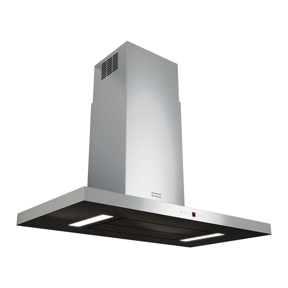
- Page 1 Instructions for use and installation Cooker Hood Istruzioni per l’uso e l’installazione Cappa Mode d’emploi et installation Hotte de Cuisine Bedienungsanleitung und Installation Dunstabzugshaube Kullanım ve montaj talimatları Davlumbaz FGB 906 IS AC...
-
Page 2: Table Of Contents
INDEX RECOMMENDATIONS AND SUGGESTIONS ........................3 CHARACTERISTICS ................................6 INSTALLATION..................................8 USE ...................................... 12 MAINTENANCE ................................... 14 INDICE CONSIGLI E SUGGERIMENTI............................16 CARATTERISTICHE................................19 INSTALLAZIONE ................................. 21 USO...................................... 25 MANUTENZIONE ................................27 SOMMAIRE CONSEILS ET SUGGESTIONS............................29 CARACTERISTIQUES................................. 32 INSTALLATION..................................34 UTILISATION .................................. -
Page 3: Recommendations And Suggestions
RECOMMENDATIONS AND SUGGESTIONS The Instructions for Use apply to several versions of this appliance. Accordingly, you may find descriptions of individual features that do not apply to your specific appliance. INSTALLATION • The manufacturer will not be held liable for any damages resulting from in- correct or improper installation. - Page 4 • If the instructions for installation for the gas hob specify a greater distance specified above, this has to be taken into account. Regulations concerning the discharge of air have to be fulfilled. • Use only screws and small parts in support of the hood. Warning: Failure to install the screws or fixing device in accordance with these instructions may result in electrical hazards.
- Page 5 • “CAUTION: Accessible parts may become hot when used with cooking ap- pliances.” MAINTENANCE • Switch off or unplug the appliance from the mains supply before carrying out any maintenance work. • Clean and/or replace the Filters after the specified time period (Fire hazard). •...
-
Page 6: Characteristics
CHARACTERISTICS Dimensions... -
Page 7: Installation
Components Ref. Q.ty Product Components Hood Canopy complete with: Controls, Light, Filters Telescopic chimney, made up of: Upper chimney Lower chimney Telescopic frame complete with Suction fan, made up 7.1a Upper frame 7.1b Lower frame Reduction flange ø 150-120 mm 14.1 Air Outlet Connector Extension Air Outlet Connector... - Page 8 INSTALLATION Drilling the Ceiling/shelf and fixing the frame DRILLING THE CEILING/SHELF • Use a plumb line to mark the centre of the hob on the ceiling/support shelf. • Place the drilling template 21 provided on the ceiling/support shelf, making sure that the template is in the correct position by lining up the axes of the template with those of the hob.
- Page 9 Fixing the frame • Loosen the two screws fastening the lower chimney and re- move this from the lower frame. • Loosen the two screws fastening the upper chimney and re- move this from the upper frame. If you wish to adjust the height of the frame, proceed as follows: •...
- Page 10 Air outlet – Recirculation Version • Insert the Connector extensions 14.1 into the side of the Con- nector 15. • Insert the Connector 15 into the Support bracket 7.3 and fix it with the screws. • Fasten the Support bracket 7.3, fixing it to the upper part with 14.1 the Screws.
- Page 11 ELECTRICAL CONNECTION • Connect the hood to the mains through a two-pole switch having a contact gap of at least 3 mm. • Remove the grease filters (see paragraph Mainte- nance) being sure that the connector of the feeding cable is correctly inserted in the socket placed on the side of the fan.
-
Page 12: Control Panel
Control panel Button Function Display Turns the suction motor on and off at speed one. Displays the set speed Decreases the working speed. Displays the set speed Increases the working speed. Displays the set speed Activates Intensive speed from any other speed, Displays HI and the time remaining alternately, once a including motor off. - Page 13 REMOTE CONTROL (OPTIONAL) The appliance can be controlled using a remote control powered by a 1.5 V carbon-zinc alkaline batteries of the standard LR03-AAA type (not included). • Do not place the remote control near to heat sources. • Used batteries must be disposed of in the proper manner.
-
Page 14: Maintenance
MAINTENANCE Opening Panel • Open the Panel by pulling it. • Clean the outside with a damp cloth and neutral detergent. • Clean the inside using a damp cloth and neutral detergent; do not use wet cloths or sponges, or jets of water; do not use abrasive substances. -
Page 15: Installation
Activated Charcoal Filter (Recirculation Version) It cannot be washed or regenerated, and must be changed when the FC symbol on the display appears, or at least once every 4 months. The Alarm signal, if it has been activated, only appears when the Suction motor is turned on. Activating the alarm signal •... - Page 16 Franke S.p.a. Via Pignolini,2 37019 Peschiera del Garda (VR) www.franke.it 991.0351.106_ver6 - 150422...
Need help?
Do you have a question about the FGB 906 IS AC and is the answer not in the manual?
Questions and answers