Sony XR-CA370 Service Manual
Fm/mw/lw cassette car stereo
Hide thumbs
Also See for XR-CA370:
- Installation/connections (2 pages) ,
- Operating instructions manual (112 pages)
Table of Contents
Advertisement
SERVICE MANUAL
Ver 1.0 2002.11
Cassette player section
Tape track
Wow and flutter
Frequency response
Signal-to-noise ratio
Tuner section
FM
Tuning range
Aerial terminal
Intermediate frequency
Usable sensitivity
Selectivity
Signal-to-noise ratio
Harmonic distortion at 1 kHz
Separation
Frequency response
MW/LW
Tuning range
Aerial terminal
Intermediate frequency
Sensitivity
Power amplifier section
Outputs
Speaker impedance
Maximum power output 45 W × 4 (at 4 ohms)
Sony Corporation
9-874-223-01
2002K0500-1
e Vehicle Company
C 2002.11
Published by Sony Engineering Corporation
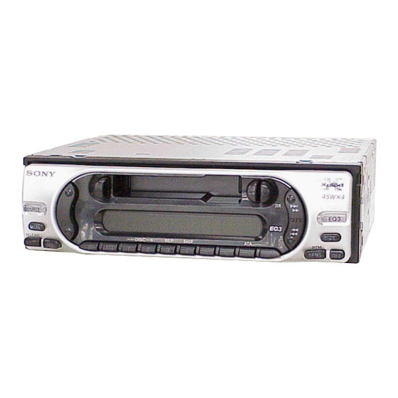
XR-CA370/CA370X
Photo: XR-CA370X
SPECIFICATIONS
4-track 2-channel stereo
0.13 % (WRMS)
30 – 15,000 Hz
55 dB
87.5 – 108.0 MHz
External aerial connector
10.7 MHz/450 kHz
9 dBf
75 dB at 400 kHz
67 dB (stereo),
69 dB (mono)
0.5 % (stereo),
0.3 % (mono)
35 dB at 1 kHz
30 – 15,000 Hz
MW: 531 – 1,602 kHz
LW: 153 – 279 kHz
External aerial connector
10.7 MHz/450kHz
MW: 30 µV
LW: 40 µV
Speaker outputs
(sure seal connectors)
4 – 8 ohms
FM/MW/LW CASSETTE CAR STEREO
Model Name Using Similar Mechanism
Tape Transport Mechanism Type
General
Outputs
Audio output
Power aerial relay control
terminal
Power amplifier control
terminal
Inputs
BUS control input terminal
BUS audio input terminal
Tone controls
Low:
±10 dB at 60 Hz (Xplod)
Mid:
±10 dB at 1 kHz (Xplod)
High:
±10 dB at 10 kHz (Xplod)
Power requirements
12 V DC car battery
(negative earth)
Approx. 178 × 50 × 178 mm
Dimensions
(w/h/d)
Approx. 182 × 53 × 161 mm
Mounting dimensions
(w/h/d)
Mass
Approx. 1.2 kg
Supplied accessories
Parts for installation and
connections (1 set)
Front panel case (1)
Design and specifications are subject to change
without notice.
CA
AEP Model
UK Model
NEW
MG-36SZ13-32
Advertisement
Table of Contents

Subscribe to Our Youtube Channel
Related Manuals for Sony XR-CA370


Summary of Contents for Sony XR-CA370
- Page 1 Outputs Speaker outputs (sure seal connectors) Speaker impedance 4 – 8 ohms Maximum power output 45 W × 4 (at 4 ohms) FM/MW/LW CASSETTE CAR STEREO Sony Corporation 9-874-223-01 2002K0500-1 e Vehicle Company C 2002.11 Published by Sony Engineering Corporation...
-
Page 2: Table Of Contents
XR-CA370/CA370X TABLE OF CONTENTS Flexible Circuit Board Repairing • Keep the temperature of the soldering iron around 270 ˚C dur- ing repairing. GENERAL • Do not touch the soldering iron on the same conductor of the Location of Controls ............3 circuit board (within 3 times). -
Page 3: General
XR-CA370/CA370X SECTION 1 This section is extracted from instruction manual. GENERAL Setting the clock Location of controls The clock uses a 24-hour digital indication. Example: To set the clock to 10:08 Press (DSPL) for 2 seconds. The hour indication flashes. - Page 4 XR-CA370/CA370X Equipment used in illustrations (not supplied) Cautions In Abbildungen dargestellte Geräte (nicht mitgeliefert) Appareils utilisés dans les illustrations (non fournis) • This unit is designed for negative earth 12 V DC operation only. Apparecchiatura utilizzata nelle illustrazioni (non in dotazione) •...
- Page 5 XR-CA370/CA370X Orient the release key correctly. Richten Sie den Löseschlüssel korrekt aus. Face the hook inwards. Orientez correctement la clé de Der Haken muss nach innen weisen. déblocage. Tournez le crochet vers l’intérieur. Orientare la chiavetta di rilascio Con il gancetto rivolto verso l’interno.
-
Page 6: Disassembly
XR-CA370/CA370X SECTION 2 DISASSEMBLY • This set can be disassembled in the order shown below. 2-1. DISASSEMBLY FLOW Note 1: The process described in can be performed in any order. Note 2: Without completing the process described in , the next process can not be performed. -
Page 7: Mechanism Deck (Mg-36Sz13-32)
XR-CA370/CA370X 2-3. MECHANISM DECK (MG-36SZ13-32) 2 two screws (PTT2.6 × 6) 2 two screws (PTT2.6 × 6) 1 connector 3 mechanism deck (CN350) (MG-36SZ13-32) 1 connector (CN300) 2-4. MAIN BOARD 4 main board 3 two screws (PTT2.6 × 6) 2 two ground point screws (PTT2.6 ×... -
Page 8: Heat Sink
XR-CA370/CA370X 2-5. HEAT SINK 1 two screws (PTT2.6 × 10) 2 heat sink 1 five screws (PTT2.6 × 10) 2-6. BRACKET (MD) 1 claw 1 claw 3 bracket (MD) 1 claw 2 four screws (B2.6 × 4) -
Page 9: Dc Motor (Capstan/Reel) (M901)
XR-CA370/CA370X 2-7. DC MOTOR (CAPSTAN/REEL) (M901) 2 main belt 3 sub belt (C) 1 two screws (P2 × 2.5) 4 DC motor (capstan/reel) (M901) Note : When installing motor, adjust the screw and screw hole of motor. 2-8. MAIN BELT, SUB BELT (C) -
Page 10: Magnetic Head (Playback) (Hp901)
XR-CA370/CA370X 2-9. MAGNETIC HEAD (PLAYBACK) (HP901) 2 screw (PTT2 × 4) 3 FF/REV lever section 1 screw (P2 × 3) 7 PSW (reel) B 9 screw (P2 × 4) 8 HP roller (A) 0 SPG support plate qa adjuster arm SPG (A) -
Page 11: Mechanical Adjustments
XR-CA370/CA370X SECTION 3 SECTION 4 MECHANICAL ADJUSTMENTS ELECTRICAL ADJUSTMENTS 1. Clean the following parts with a denatured-alcohol-moistened TAPE DECK SECTION 0 dB= 0.775 V swab: playback head pinch roller 1. The adjustments should be performed in the order given in... -
Page 12: Tuner Section
XR-CA370/CA370X TAPE SPEED ADJUSTMENT Setting: test tape WS-48A frequency counter (3 kHz, 0 dB) 4 Ω – speaker out terminal Procedure: 1. Put the set into the FWD PB mode. 2. Adjust adjustment resistor for inside capstan motor so that the reading on the frequency counter becomes in 3,015 Hz. -
Page 13: Diagrams
XR-CA370/CA370X SECTION 5 DIAGRAMS 5-1. NOTE FOR PRINTED WIRING BOARDS AND SCHEMATIC DIAGRAMS Note on Printed Wiring Board: Note on Schematic Diagram: • X : parts extracted from the component side. • All capacitors are in µF unless otherwise noted. pF: µµF •... - Page 14 XR-CA370/CA370X • Waveforms – MAIN Board – – CONTROL Board – 1 IC1 qs (OSC2) 4 IC900 ud (OSC) 3.1 Vp-p 2.4 Vp-p 54.3 ns 21.1 µs 2 IC1 qh (XO) 5.1 Vp-p 30.5 µs 3 IC200 4 (OSCO) 4.9 Vp-p...
-
Page 15: Printed Wiring Board - Main Board
5-2. PRINTED WIRING BOARD – MAIN Board – • Semiconductor Location Ref. No. Location CN400 CN800 D250 AUDIO (BUS CONTROL IN) D253 AUDIO IN (FOR SONY BUS) WHT/BLK D300 ANT100 (ANTENNA) F901 D350 H-10 GRN/BLK (FRONT VIEW) D451 VIO/BLK CN700... -
Page 16: Schematic Diagram - Main Board (1/2)
XR-CA370/CA370X 5-3. SCHEMATIC DIAGRAM – MAIN Board (1/2) – • • See page 14 for Waveforms. See page 20 for IC Block Diagram. (1/2) TU100 TUX-030 TUNER UNIT ANT100 (FM/AM ANTENNA) R101 C103 C100 C101 C102 0.047 0.001 0.001 C106... -
Page 17: Schematic Diagram - Main Board (2/2)
11ES2 MTZJ9.1C PDTC114EK R663 PST3443UL Q451 100k Q725 PDTC144EK C451 C734 C731 PDTC114EK 0.047F 0.01 5.5V CN800 BUS CONTROL IN (FOR SONY BUS) R710 D807 Q710 11ES2 R713 2SA1428 1/2W BUS5 DATA BUS-ON D740 11ES2 R814 BUS4 DATA BUS-DATA 220k... -
Page 18: Printed Wiring Board - Control Board
XR-CA370/CA370X 5-5. PRINTED WIRING BOARD – CONTROL Board – D921, S969, 976 CONTROL BOARD (COMPONENT SIDE) > D910 – 912, 914 – 916, S974 D918 – 922, 924, 930, S969 D932 – 937, 941 – 944 S958 S976 SEEK S980... -
Page 19: Schematic Diagram - Control Board
XR-CA370/CA370X 5-6. SCHEMATIC DIAGRAM – CONTROL Board – • See page 14 for Waveform. LCD1 LIQUID CRYSTAL DISPLAY ∗ ∗ ∗ ∗ ∗ R965 R935 R916,921,932 R911,913 R962 (CA370) (CA370) (CA370) (CA370) (CA370) (CA370X) (CA370X) (CA370X) (CA370X) (CA370X) R960 R965... -
Page 20: Ic Pin Function Description
SYS-RES System reset signal output to the SONY bus interface “L”: reset BUS-ON Bus interface control signal output to the SONY bus interface “L”: uni-link on KEYACK Key acknowledge signal detection input from the liquid crystal display driver IC400 BD3803F-FE2... - Page 21 Serial data transfer clock signal output to the tuner unit Illumination color selection signal input “L”: amber illumination “H”: green illumination COL-SEL (XR-CA370:fixed at “H” in this set, XR-CA370X:fixed at “L” in this set) 77 to 82 Not used Power on/off control signal output of the illumination LED and LCD back light ILL-ON “H”: power on...
-
Page 22: Exploded Views
XR-CA370/CA370X SECTION 6 EXPLODED VIEWS NOTE: • -XX and -X mean standardized parts, so they • Items marked “*” are not stocked since they may have some difference from the original are seldom required for routine service. Some one. delay should be anticipated when ordering •... -
Page 23: Front Panel Section
XR-CA370/CA370X 6-2. FRONT PANEL SECTION not supplied (control board) not supplied not supplied not supplied LCD1 not supplied not supplied not supplied not supplied not supplied Ref. No. Part No. Description Remark Ref. No. Part No. Description Remark A-3315-980-A PANEL ASSY, FRONT (CA370X) -
Page 24: Main Board Section
XR-CA370/CA370X 6-3. MAIN BOARD SECTION main board not supplied TU100 Ref. No. Part No. Description Remark Ref. No. Part No. Description Remark A-3274-623-A MAIN BOARD, COMPLETE (CA370X) TU100 A-3220-887-A TUNER UNIT (TUX-030) 7-685-794-09 SCREW +PTT 2.6X10 (S) A-3274-657-A MAIN BOARD, COMPLETE (CA370) -
Page 25: Mechanism Deck Section (Mg-36Sz13-32)
XR-CA370/CA370X 6-4. MECHANISM DECK SECTION (MG-36SZ13-32) not supplied HP901 not supplied not supplied M901 not supplied S902 S903 not supplied not supplied S901 not supplied not supplied (slide SW board) not supplied not supplied not supplied Ref. No. Part No. -
Page 26: Electrical Parts List
XR-CA370/CA370X SECTION 7 ELECTRICAL PARTS LIST CONTROL NOTE: When indicating parts by reference • Due to standardization, replacements in the • Items marked “*” are not stocked since they number, please include the board. parts list may be different from the parts speci- are seldom required for routine service. - Page 27 XR-CA370/CA370X CONTROL MAIN Ref. No. Part No. Description Remark Ref. No. Part No. Description Remark R911 1-216-810-11 RES-CHIP 1/10W A-3274-623-A MAIN BOARD, COMPLETE (CA370X) (CA370) A-3274-657-A MAIN BOARD, COMPLETE (CA370) R911 1-216-814-11 RES-CHIP 1/10W ********************* (CA370X) R912 1-216-025-11 RES-CHIP 1/10W 3-041-578-01 BRACKET (IC) 7-685-794-09 SCREW +PTT 2.6X10 (S)
- Page 28 XR-CA370/CA370X MAIN Ref. No. Part No. Description Remark Ref. No. Part No. Description Remark C403 1-125-891-11 CERAMIC CHIP 0.47uF C404 1-125-891-11 CERAMIC CHIP 0.47uF < CONNECTOR/JACK > C405 1-125-891-11 CERAMIC CHIP 0.47uF * CN300 1-564-705-11 PIN, CONNECTOR (PC BOARD) 3P...
- Page 29 XR-CA370/CA370X MAIN Ref. No. Part No. Description Remark Ref. No. Part No. Description Remark JC75 1-216-864-11 SHORT CHIP 1-216-809-11 METAL CHIP 1/10W JC83 1-216-864-11 SHORT CHIP 1-216-809-11 METAL CHIP 1/10W JC91 1-216-864-11 SHORT CHIP 1-216-809-11 METAL CHIP 1/10W JC104 1-216-864-11 SHORT CHIP...
- Page 30 XR-CA370/CA370X MAIN Ref. No. Part No. Description Remark Ref. No. Part No. Description Remark R502 1-216-833-11 METAL CHIP 1/10W R206 1-249-393-11 CARBON 1/4W R503 1-216-821-11 METAL CHIP 1/10W R207 1-249-393-11 CARBON 1/4W R504 1-216-841-11 METAL CHIP 1/10W R208 1-216-813-11 RES-CHIP...
- Page 31 XR-CA370/CA370X MAIN Ref. No. Part No. Description Remark Ref. No. Part No. Description Remark 1-567-098-41 VIBRATOR, CRYSTAL (32.768kHz) PARTS FOR INSTALLATION AND CONNECTIONS X200 1-579-242-11 VIBRATOR, CRYSTAL (4.332MHz) ************************************** ************************************************************** X-3382-647-1 FRAME ASSY, FITTING MISCELLANEOUS 3-386-828-21 SCREW, FITTING 3-349-410-11 BUSHING...
- Page 32 XR-CA370/CA370X REVISION HISTORY Clicking the version allows you to jump to the revised page. Also, clicking the version at the upper right on the revised page allows you to jump to the next revised page. Ver. Date Description of Revision...
Need help?
Do you have a question about the XR-CA370 and is the answer not in the manual?
Questions and answers