Sony XR-CA350X Service Manual
Fm/am cassette car stereo
Hide thumbs
Also See for XR-CA350X:
- Operating instructions manual (36 pages) ,
- Installation/connections (5 pages) ,
- Specification (2 pages)
Table of Contents
Advertisement
Quick Links
SERVICE MANUAL
Ver 1.0 2002.11
AUDIO POWER SPECIFICATIONS (US model)
POWER OUTPUT AND TOTAL HARMONIC DISTORTION
22 watts per channel minimum continuous average power into 4
ohms, 4 channels driven from 20 Hz to 20 kHz with no more than
5 % total harmonic distortion.
Other specifications
Cassette player section
Tape track
Wow and flutter
Frequency response
Signal-to-noise ratio
Tuner section
FM
Tuning range
Antenna terminal
Intermediate frequency
Usable sensitivity
Selectivity
Signal-to-noise ratio
Harmonic distortion at 1 kHz
Separation
Frequency response
AM
Tuning range
Antenna terminal
Intermediate frequency
Sensitivity
Power amplifier section
Outputs
Speaker impedance
Maximum power output 45 W × 4 (at 4 ohms)
Sony Corporation
9-874-222-01
2002K0500-1
e Vehicle Company
C 2002.11
Published by Sony Engineering Corporation
XR-CA350X
Model Name Using Similar Mechanism
Tape Transport Mechanism Type
SPECIFICATIONS
General
4-track 2-channel stereo
Outputs
0.13 % (WRMS)
30 – 15,000 Hz
55 dB
Inputs
Tone controls
FM tuning interval:
87.5 – 107.9 MHz
(at 200 kHz step)
External antenna connector
10.7 MHz/450 kHz
Power requirements
9 dBf
75 dB at 400 kHz
Dimensions
67 dB (stereo),
69 dB (mono)
Mounting dimensions
0.5 % (stereo),
0.3 % (mono)
35 dB at 1 kHz
Mass
30 – 15,000 Hz
Supplied accessories
AM tuning interval:
530 – 1,710 kHz
(at 10 kHz step)
Design and specifications are subject to change
External antenna connector
without notice.
10.7 MHz/450 kHz
30 µV
Speaker outputs
(sure seal connectors)
4 – 8 ohms
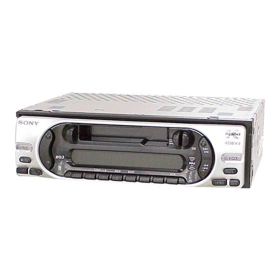
FM/AM CASSETTE CAR STEREO
US Model
Canadian Model
NEW
MG-36SZ13-32
Audio output
Power antenna relay
control lead
Power amplifier control
lead
BUS control input terminal
BUS audio input terminal
Low:
±10 dB at 60 Hz (Xplod)
Mid:
±10 dB at 1 kHz (Xplod)
High:
±10 dB at 10 kHz (Xplod)
12 V DC car battery
(negative ground)
Approx. 178 × 50 × 178 mm
× 2 × 7
(7
1
/
1
/
in)
8
8
(w/h/d)
Approx. 182 × 53 × 161 mm
× 2
× 6
(7
1
/
1
/
3
/
in)
4
8
8
(w/h/d)
Approx. 1.2 kg (2 lb 10 oz)
Parts for installation and
connections (1 set)
Front panel case (1)
Advertisement
Table of Contents

Related Manuals for Sony XR-CA350X


Summary of Contents for Sony XR-CA350X
-
Page 1: Specifications
Outputs Speaker outputs (sure seal connectors) Speaker impedance 4 – 8 ohms FM/AM CASSETTE CAR STEREO Maximum power output 45 W × 4 (at 4 ohms) Sony Corporation 9-874-222-01 2002K0500-1 e Vehicle Company C 2002.11 Published by Sony Engineering Corporation... -
Page 2: Table Of Contents
XR-CA350X TABLE OF CONTENTS Flexible Circuit Board Repairing • Keep the temperature of the soldering iron around 270 ˚C dur- ing repairing. GENERAL • Do not touch the soldering iron on the same conductor of the Location of Controls ............3 circuit board (within 3 times). -
Page 3: General
XR-CA350X SECTION 1 This section is extracted from instruction manual. GENERAL Setting the clock Location of controls The clock uses a 12-hour digital indication. Example: To set the clock to 10:08 Press (DSPL) for 2 seconds. The hour indication flashes. - Page 4 XR-CA350X Equipment used in illustrations (not supplied) Cautions Connection example (2) Appareils utilisés dans les illustrations (non fournis) Notes (2-B- •This unit is designed for negative ground 12 V • Be sure to connect the ground cord before DC operation only.
- Page 5 XR-CA350X Supplied with XA-C30 Fourni avec le XA-C30 Source selector (not supplied) Sélecteur de source Supplied with the CD/MD changer (non fourni) Fourni avec le changeur de CD/MD XA-C30 BUS AUDIO IN BUS CONTROL IN from car antenna de l’antenne de la voiture...
-
Page 6: Reset Button
Japanese cars. In such a case, consult switch •Avoid installing the unit in areas subject to the unit. your Sony dealer. dust, dirt, excessive vibration, or high Be sure to press (OFF) on the unit for two temperatures, such as in direct sunlight or near Remove the protection collar 3. -
Page 7: Disassembly
XR-CA350X SECTION 2 DISASSEMBLY • This set can be disassembled in the order shown below. 2-1. DISASSEMBLY FLOW Note 1: The process described in can be performed in any order. Note 2: Without completing the process described in , the next process can not be performed. -
Page 8: Mechanism Deck (Mg-36Sz13-32)
XR-CA350X 2-3. MECHANISM DECK (MG-36SZ13-32) 2 two screws (PTT2.6 × 6) 2 two screws (PTT2.6 × 6) 1 connector 3 mechanism deck (CN350) (MG-36SZ13-32) 1 connector (CN300) 2-4. MAIN BOARD 4 main board 3 two screws (PTT2.6 × 6) 2 two ground point screws (PTT2.6 ×... -
Page 9: Heat Sink
XR-CA350X 2-5. HEAT SINK 1 two screws (PTT2.6 × 10) 2 heat sink 1 five screws (PTT2.6 × 10) 2-6. BRACKET (MD) 1 claw 1 claw 3 bracket (MD) 1 claw 2 four screws (B2.6 × 4) -
Page 10: Dc Motor (Capstan/Reel) (M901)
XR-CA350X 2-7. DC MOTOR (CAPSTAN/REEL) (M901) 2 main belt 3 sub belt (C) 1 two screws (P2 × 2.5) 4 DC motor (capstan/reel) (M901) Note : When installing motor, adjust the screw and screw hole of motor. 2-8. MAIN BELT, SUB BELT (C) -
Page 11: Head (Playback) (Hp901)
XR-CA350X 2-9. MAGNETIC HEAD (PLAYBACK) (HP901) 2 screw (PTT2 × 4) 3 FF/REV lever section 1 screw (P2 × 3) 7 PSW (reel) B 9 screw (P2 × 4) 8 HP roller (A) 0 SPG support plate qa adjuster arm SPG (A) -
Page 12: Mechanical Adjustments
XR-CA350X SECTION 3 SECTION 4 MECHANICAL ADJUSTMENTS ELECTRICAL ADJUSTMENTS 1. Clean the following parts with a denatured-alcohol-moistened TAPE DECK SECTION 0 dB= 0.775 V swab: playback head pinch roller 1. The adjustments should be performed in the order given in... -
Page 13: Tuner Section
XR-CA350X TAPE SPEED ADJUSTMENT Setting: test tape WS-48A frequency counter (3 kHz, 0 dB) 4 Ω – speaker out terminal Procedure: 1. Put the set into the FWD PB mode. 2. Adjust adjustment resistor for inside capstan motor so that the reading on the frequency counter becomes in 3,015 Hz. -
Page 14: Diagrams
XR-CA350X SECTION 5 DIAGRAMS 5-1. NOTE FOR PRINTED WIRING BOARDS AND SCHEMATIC DIAGRAMS Note on Printed Wiring Board: Note on Schematic Diagram: • X : parts extracted from the component side. • All capacitors are in µF unless otherwise noted. pF: µµF •... -
Page 15: Printed Wiring Board - Main Board
PRINTED WIRING BOARD – MAIN Board – • Semiconductor Location Ref. No. Location D250 CN400 CN800 D253 AUDIO (BUS CONTROL IN) D300 AUDIO IN (FOR SONY BUS) D350 H-10 ANT100 F901 (ANTENNA) D451 (FRONT VIEW) D452 CN700 FRONT LCH (+) MAIN BOARD WHT/BLK D500 FRONT LCH (–) -
Page 16: Schematic Diagram - Main Board (1/2)
XR-CA350X 5-3. SCHEMATIC DIAGRAM – MAIN Board (1/2) – • See page 20 for Waveforms. (1/2) TU100 TUX-030 TUNER UNIT ANT100 (FM/AM ANTENNA) R101 C100 0.047 C106 C105 R102 C104 R105 R106 (CHASSIS) Q251 R263 Q252 2SD1664 2PB710A R259 R250... -
Page 17: Schematic Diagram - Main Board (2/2)
11ES2 MTZJ9.1C PDTC114EK R663 PST3443UL Q451 100k Q725 PDTC144EK C451 C734 C731 PDTC114EK 0.047F 0.01 5.5V CN800 BUS CONTROL IN (FOR SONY BUS) R710 D807 Q710 11ES2 R713 2SA1428 1/2W BUS5 DATA BUS-ON D740 11ES2 R814 BUS4 DATA BUS-DATA 220k... -
Page 18: Printed Wiring Board - Control Board
XR-CA350X 5-5. PRINTED WIRING BOARD – CONTROL Board – D921, S969, 976 CONTROL BOARD (COMPONENT SIDE) > D910 – 912, 914, 916, S974 D918 – 922, 924, 930, 932, S969 D934 – 937, 941 – 944 S958 S976 SEEK S980... -
Page 19: Schematic Diagram - Control Board
XR-CA350X 5-6. SCHEMATIC DIAGRAM – CONTROL Board – • See page 20 for Waveform. LCD1 LIQUID CRYSTAL DISPLAY R960 R965 R935 R932 R916 R913 R911 R921 R961 R966 R934 R931 R915 R912 R910 R920 R962 S955,978 S951 S960 DISC -... - Page 20 XR-CA350X • Waveforms • IC Block Diagrams – MAIN Board – – CONTROL Board – – MAIN Board – IC800 MM1175XFF IC400 BD3803F-FE2 1 IC1 qs (OSC2) 4 IC900 ud (OSC) BUS ON RESET RESET RESET SWITCH 3.1 Vp-p 2.4 Vp-p...
-
Page 21: Ic Pin Function Description
Not used SYS-RES System reset signal output to the SONY bus interface “L”: reset BUS-ON Bus interface control signal output to the SONY bus interface “L”: uni-link on KEYACK Key acknowledge signal detection input from the liquid crystal display driver DAVN... - Page 22 XR-CA350X Pin No. Pin Name Description Audio line muting on/off control signal output “H”: muting on 51 to 53 Not used TU-ATT Tuner muting on/off control signal output to the tuner unit “L”: muting on 55, 56 Not used LO/DX Local/DX selection signal output terminal “L”: DX, “H”: local Not used...
-
Page 23: Exploded Views
XR-CA350X SECTION 6 EXPLODED VIEWS NOTE: • -XX and -X mean standardized parts, so they • Items marked “*” are not stocked since they may have some difference from the original are seldom required for routine service. Some one. delay should be anticipated when ordering •... -
Page 24: Front Panel Section
XR-CA350X 6-2. FRONT PANEL SECTION not supplied (control board) not supplied not supplied not supplied LCD1 not supplied not supplied not supplied not supplied not supplied Ref. No. Part No. Description Remark Ref. No. Part No. Description Remark A-3315-947-A PANEL ASSY, FRONT... -
Page 25: Main Board Section
XR-CA350X 6-3. MAIN BOARD SECTION main board not supplied TU100 Ref. No. Part No. Description Remark Ref. No. Part No. Description Remark TU100 A-3220-887-A TUNER UNIT (TUX-030) A-3274-608-A MAIN BOARD, COMPLETE * 102 3-041-578-01 BRACKET (IC) 7-685-794-09 SCREW +PTT 2.6X10 (S) -
Page 26: Mechanism Deck Section (Mg-36Sz13-32)
XR-CA350X 6-4. MECHANISM DECK SECTION (MG-36SZ13-32) not supplied HP901 not supplied not supplied M901 not supplied S902 S903 not supplied not supplied S901 not supplied not supplied (slide SW board) not supplied not supplied not supplied Ref. No. Part No. -
Page 27: Electrical Parts List
XR-CA350X SECTION 7 ELECTRICAL PARTS LIST CONTROL NOTE: When indicating parts by reference • Due to standardization, replacements in the • Items marked “*” are not stocked since they number, please include the board. parts list may be different from the parts speci- are seldom required for routine service. - Page 28 XR-CA350X MAIN Ref. No. Part No. Description Remark Ref. No. Part No. Description Remark C422 1-125-891-11 CERAMIC CHIP 0.47uF A-3274-608-A MAIN BOARD, COMPLETE C423 1-125-891-11 CERAMIC CHIP 0.47uF C424 1-125-891-11 CERAMIC CHIP 0.47uF ********************* 3-041-578-01 BRACKET (IC) C425 1-125-891-11 CERAMIC CHIP 0.47uF...
- Page 29 XR-CA350X MAIN Ref. No. Part No. Description Remark Ref. No. Part No. Description Remark D452 8-719-110-03 DIODE RD7.5ESB2 D500 8-719-200-82 DIODE 11ES2 < TRANSISTOR > D501 8-719-200-82 DIODE 11ES2 D502 8-719-200-82 DIODE 11ES2 Q251 8-729-920-85 TRANSISTOR 2SD1664-QR D503 8-719-200-82 DIODE 11ES2...
- Page 30 XR-CA350X MAIN Ref. No. Part No. Description Remark Ref. No. Part No. Description Remark 1-216-864-11 SHORT CHIP R405 1-216-809-11 METAL CHIP 1/10W R406 1-216-841-11 METAL CHIP 1/10W 1-216-845-11 METAL CHIP 100K 1/10W R407 1-216-841-11 METAL CHIP 1/10W 1-249-441-11 CARBON 100K...
- Page 31 XR-CA350X MAIN Ref. No. Part No. Description Remark Ref. No. Part No. Description Remark PARTS FOR INSTALLATION AND CONNECTIONS R800 1-216-833-11 METAL CHIP 1/10W ************************************** R801 1-216-809-11 METAL CHIP 1/10W R802 1-216-809-11 METAL CHIP 1/10W X-3382-647-1 FRAME ASSY, FITTING R804...
- Page 32 XR-CA350X REVISION HISTORY Clicking the version allows you to jump to the revised page. Also, clicking the version at the upper right on the revised page allows you to jump to the next revised page. Ver. Date Description of Revision...
Need help?
Do you have a question about the XR-CA350X and is the answer not in the manual?
Questions and answers