Advertisement
CONTENTS:
Notices
Troubleshooting Guides:
User interface
Flow charts
PCB assy - Main
PCB assy - Host
PCB assy - Frnt Panel
PCB assy - Analog I/O
PCB assy - Spkr Out
Schematics/drawings
Fender Musical Instruments Corp. 8860 E. Chaparral Road Suite 100 Scottsdale, AZ 85258
p/n 022-9002-000 (120V)
Advertisement
Table of Contents

Related Manuals for Fender CYBER-TWIN HEAD


Summary of Contents for Fender CYBER-TWIN HEAD
-
Page 1: Table Of Contents
PCB assy - Main PCB assy - Host PCB assy – Frnt Panel PCB assy – Analog I/O PCB assy – Spkr Out Chassis assembly Cabinet assembly End item Schematics/drawings Fender Musical Instruments Corp. 8860 E. Chaparral Road Suite 100 Scottsdale, AZ 85258... -
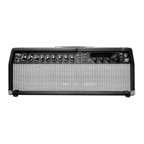
Page 2: Cyber-Twin Head
Fender Musical Instruments Co. All specifications subject to change without notice. For warranty repair service, only Fender specified part numbers are to be used. It is recommended they also be used for post-warranty maintenance and repair. -
Page 3: Specifications
CYBER-TWIN HEAD SPECIFICATIONS Product Release No.: PR 502 (This is not a model number) Part Number: 120V Version : 22-9002 110V TW 22-9012 240V Aus 22-9032 230V UK 22-9042 230V Arg 22-9052 230V Eur 22-9062 100V Jpn 22-9072 220V R.O.K. :... -
Page 4: Step By Step
Step by Step Fender Cyber-Twin Troubleshooting Guide for Hardware Problems NO AUDIO Setup: Follow the instructions as stated under notes 8, on the Cyber-Twin Head Main Schematics (0057498000 Sheet 1). 1. Turn on the Power to the Cyber-Twin. 2. Does the Jewel LED come on? 1.1 If the Jewel LED does not come on, but there is Audio, check the Jewel LED. - Page 5 4 If the ribbon cable on P6 is OK, swap the Host PCB, otherwise swap the ribbon cable on P6. NO AUDIO ON HEADPHONES JACK Setup: Follow the instructions as stated under notes 8, on the Cyber-Twin Head Main Schematics (0057498000 Sheet1).
- Page 6 CYBER-TWIN HEAD NO AUDIO ON HEADPHONES JACK (cont) 3. If there is Audio Output through the Speakers, check if ribbon cable P3 is OK. 3.1 If the ribbon cable is OK, then swap the Analog I/O PCB. 3.2 If the ribbon cable is defective, then swap the cable.
- Page 7 CYBER-TWIN HEAD Fender Cyber-Twin Troubleshooting Guide for User Interface Problems NO SOUND What to check: The LED ladder is not coming on when hitting a string. The TRIM, GAIN, VOLUME or MASTER is turned to 1. Something is plugged into the L/MONO EFFECTS RETURN jack, or the HEADPHONES jack.
- Page 8 CYBER-TWIN HEAD NO REVERB What to check: The REVERB control is turned to 1. The REVERB INPUT is turned to 1.0. FX Kill switch is enabled. How to solve the problem: Turn the REVERB knob on the front panel past 1.
- Page 9 CYBER-TWIN HEAD AMP DOES NOT LOAD PRESETS OR WILL NOT SAVE A PRESET What to check: DEMO MODE is turned ON. MEMORY PROTECT is turned ON. How to solve the problem: Press the UTILITY menu button 1x to go to the DEMO MODE function and turn DEMO MODE OFF.
- Page 10 CYBER-TWIN HEAD MIDI FOOT-PEDAL DOES NOT WORK What to check: The MIDI RECEIVE CHANNEL on the Cybertwin is set to a different channel than the transmitting MIDI device. The CONTINUOUS CONTROLLER on the Cybertwin is set to a different CONTINUOUS CONTOLLER value on the foot-pedal.
- Page 11 CYBER-TWIN HEAD FOOT CONTROLLER CHANGES WILL NOT RECORD IN SEQUENCER What to check: The CC ECHO IN OUT is turned OFF. How to solve the problem: Press the UTILITY menu button 9x to get to the CC ECHO IN OUT function and switch it to...
- Page 12 NO AUDIO Power Switch Jewel LED Audio Audio Audio Check Check Speakers Plugged In Check Power Supplies Jewel LED Power Supplies (Remove any plugs from the rear panel) Power Supplies Plug In Troubleshoot Ribbon Cables Troubleshoot Speakers Power Supplies Power Supplies Audio on Swap Swap...
- Page 13 MOTOR POT DOES NOT WORK Run Motor Pot Test described on Motor Pot A/D Section Schematic (0055766000) Motor Pot Power Supplies Voltage on PW Troubleshoot Power Pins 1-8 while Supplies in Motor Pot A/D running Pot test Section on Main PCB (0055766000) Swap Motor Voltage on Pin1&3 of...
- Page 14 MIDI IS NOT WORKING Do Midi Test as described on Digital I/O Board Section Schematics (0055766000) Midi Activity on TP 47,48,49 Midi is Midi Activity on working P5B Pin1&3 Swap Ribbon Cable on P5 Digital I/O PCB (0055766000) Ribbon Cable on P6 Swap Ribbon Cable on P5...
- Page 15 HEADPHONES ARE NOT WORKING Audio Output through Speakers with Headphones unplugged Proceed to Ribbon Cable NO AUDIO on P3 OK worksheet Swap Swap Ribbon Cable Analog I/O PCB on P3 (0056333000)
- Page 16 FX KILL/ FOOTSWITCH IS NOT WORKING See Footswitch Notes on Digital I/O Board Section Schematics (0055766000) Voltage on U26 Pins 4,5,10,11,12 Power Digital Activity Supply on U26 Pins 7&15 Troubleshoot Troubleshoot area Ribbon Cable P4 Digital Activity Power Supply around J3 or J5 on U26 Pin 13 Swap Ribbon Ribbon Cable P7...
-
Page 17: Cyber-Twin Presets
Cyber-Twin Presets... -
Page 18: Parts List
CYBER-TWIN HEAD PARTS LIST NOTE: SHADED ITEMS ARE FOR REFERENCE ONLY PRINTED CIRCUIT BOARD ASSEMBLY – MAIN PART # DESCRIPTION REFERENCE DESIGNATION 0029719000 CABLE FLAT 5 CKT 10” PW9A PW9B 0038689001 CAP AE AX .47uF 100V 20% C52 C97 0038692001... - Page 19 CYBER-TWIN HEAD PRINTED CIRCUIT BOARD ASSEMBLY – MAIN (Cont) PART # DESCRIPTION REFERENCE DESIGNATION 0024845000 CAP MPF RDL .047uF 400V 10% C8 C24-25 0051931000 CONNECTOR DIN 5 PIN FEMALE J3 J6-8 0055993000 CONTROL MOTORIZED 10kB R80 R104 R123 R137 R144 R150 R162 R168...
- Page 20 CYBER-TWIN HEAD PRINTED CIRCUIT BOARD ASSEMBLY – MAIN (Cont) PART # DESCRIPTION REFERENCE DESIGNATION 0025117001 RES CF 1/2W 5% 220k LL R213-214 0031065001 RES CF 1/2W 5% 91k LL 0028842001 RES CF 1/4W 5% 1.1k LL R236-237 R420-421 0028862001 RES CF 1/4W 5% 1.3k LL...
- Page 21 CYBER-TWIN HEAD PRINTED CIRCUIT BOARD ASSEMBLY – MAIN (Cont) PART # DESCRIPTION REFERENCE DESIGNATION 0026507001 RES CF 1/4W 5% 62k LL 0028153001 RES CF 1/4W 5% 75k LL 0029613001 RES CF 1/4W 5% 91k LL R74 R76 0027349001 RES FILM 1W 5% 10k LL...
- Page 22 CYBER-TWIN HEAD PRINTED CIRCUIT BOARD ASSEMBLY – HOST PART # DESCRIPTION REFERENCE DESIGNATION 0053556004 CAP 0805 CER .01uF 16V 5% C33-34 C37-39 C46 C51 0053554004 CAP 0805 CER .1uF 16V 5% C2 C6-7 C11 C14 C17 C19 C23 C25-32 C35-36 C40-41 C43...
- Page 23 CYBER-TWIN HEAD PRINTED CIRCUIT BOARD ASSEMBLY – FRONT PANEL PART # DESCRIPTION REFERENCE DESIGNATION 0053554004 CAP CER 0805 .1uF 16V 10% C8-15 C18 C20-24 0055953004 CAP CER 0805 .33uF 16V 5% 0055956004 CAP CER 0805 33pF 25V 5% C1-7 C16 C19...
-
Page 24: Chassis Assembly
PRINTED CIRCUIT BOARD ASSEMBLY – SPKR OUT PART # DESCRIPTION REFERENCE DESIGNATION 0029175000 JACK PHONE 1/4” HI CURRENT PC SPEAKER OUTPUT JACKS 0057655000 PCB FAB CYBER-TWIN HEAD SPKR OUT CHASSIS ASSEMBLY PART # DESCRIPTION REFERENCE DESIGNATION 0056316000 BEZEL ASSY CYBER-TWIN 0056526000 CABLE ASSY RIBBON 2x7 CKT 5.25”... -
Page 25: Cabinet Assembly
@ REAR PANEL 0055849000 CHASSIS CYBER-TWIN 0055949000 PANEL FRONT CYBER-TWIN 0057496000 PANEL REAR CYBER-TWIN HEAD 0057497000 PANEL REAR CYBER-TWIN HEAD R.O.K. 0054798000 JEWEL ASSY LED 0055732000 PUSH NUT 1/8” POST @ BEZEL ASSY 0014999000 SCRW M 6-32x1/4 PHP BLX @ REAR BREAK-AWAY... -
Page 26: End Item
CABINET ASSEMBLY CYBER-TWIN HEAD 0057640000 CHS ASSY CYBER-TWIN HEAD 120V 0057642000 CHS ASSY CYBER-TWIN HEAD 230V 0057644000 CHS ASSY CYBER-TWIN HEAD 100V JPN 0057641000 CHS ASSY CYBER-TWIN HEAD 220V R.O.K. 0057643000 CHS ASSY CYBER-TWIN HEAD 240V AUS 0047248000 CORD PWR W/IEC CONN DOM...
Need help?
Do you have a question about the CYBER-TWIN HEAD and is the answer not in the manual?
Questions and answers