
Related Manuals for HITEC X1 mini


Summary of Contents for HITEC X1 mini
- Page 1 OPERATION MANUAL WARNING: THE CHARGING AND DISCHARGING OF RC HOBBY BATTERIES CAN BE DANGEROUS. FAILURE TO FOLLOW THE INSTRUCTIONS AND WARNINGS IN THIS MANUAL MAY RESULT IN PROPERTY DAMAGE AND/OR LOSS OF LIFE.
-
Page 2: Table Of Contents
By following the guidelines and recommendations provided, you are Input Functions ..........................13 sure to enjoy many years of R/C fun with your new X1 mini charger! Program Flow Chart........................14 THE CHARGING AND DISCHARGING OF RC HOBBY BATTERIES CAN BE Charger Operation........................16... -
Page 3: Warning And Safety Notes
Warning and Safety Notes [cont.] Hitec RCD USA will not be held responsible for any damages or injuries that may To avoid a short circuit between the charge lead, always connect the charge occur by persons who fail to follow these warnings or who fail to properly follow cable to the charger rst, then connect the battery. - Page 4 ALWAYS be veri ed before charging a Lithium battery at rates higher than 1C. If you wish to perform a Lithium break-in on the bench with the X1 mini, Voltage is just as critical as the charging amperage rate and this is determined discharging to minimum acceptable voltages and performing a balance charge by the number of cells in series, or “S”.
-
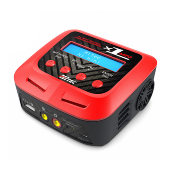
Page 5: Product Layout
AC Input 100 - 240 Volts AC The Set Contains: Total Charge Circuit Power 60 Watts AC input 1 x X1 mini Charger Charge Current Range 0.1 - 6.0 Amps 1 x Power Cord Discharge Current Range 0.1 - 2.0 Amps... -
Page 6: Features
Battery Memory (Data Store/Load): This automatic charge termination program is based on the principle of the The X1 mini is capable of storing up to 10 di erent charge/discharge pro les for Delta-peak voltage detection. When the battery’s voltage exceeds the threshold, your convenience. -
Page 7: Input Functions
Battery & Power Supply Connections Input Functions 1.) Connecting to Power Source: It is an AC charger only. Please insert the AC power cord to the wall socket (100- 240V) directly to power it on. 2.) Connecting the Battery: Important!!! Before connecting a battery, it is absolutely essential to check one last time that you have set the parameters correctly. -
Page 8: Program Flow Chart
(2) The other method is by manually setting up the charge or discharge process NiMH CHARGE NiMH DISCHARGE BATT/PROGRAM START each time. The X1 mini is capable of the following processes: NiMH BATT CURRENT 2.0A 0.1A CUT: 1.0V ENTER BATT/PROGRAM... - Page 9 Charger Operation Charger Operation [cont.] [cont.] The following steps describe how to manualy setup the X1 mini: If both numbers are identical, press START/ENTER to begin the charging process. 3. BATT/PROGRAM Select: Press INC and DEC to scroll through all programs and press START/ENTER to enter the LiPo BATT Program.
-
Page 10: Memory Preset - Data Store/Load
10 batteries per channel. Data can be saved for each button to con rm your selection. battery type and each charge mode available with the X1 mini. This allows you to recall data for each battery when charging or discharging without having to set up MAKE SURE TO FOLLOW YOUR BATTERY MANUFACTURERS the program over again. -
Page 11: Battery Meter
Battery Meter Battery Resistance Measurement Battery Meter: Battery Resistance Measurement: The user can check the battery’s total voltage, the highest voltage, the lowest The user can check the battery’s total resistance, the highest resistance, the voltage and each cell’s voltage in the battery pack. lowest resistance and each cell’s resistance in the battery pack. -
Page 12: Advanced System Set Up
Advanced System Set Up Advanced System Set Up [ cont.] The system will be set to its default parameters when powered on for the rst ITEM SELECTION DESCRIPTION time. The screen displays the following information in sequence and the user can change any given value on each screen. -
Page 13: Warning And Error Messages
Warning and Error Messages Using the Charge Master PC Software In the case of an error, the screen will communicate the cause of the error and The free “Charge Master” software gives you unparalleled ability to operate the emit an audible sound. charger through your PC computer. -
Page 14: Conformity Declarations
Final Charge Voltage: The voltage at which the battery’s charge limit (capacity Hitec's X1 mini satis es all relevant and mandatory CE directives and complies limit) is reached after which the charge process switches from a high current with FCC Part 15 Subpart B: 2010. -
Page 15: Disposal And Prop 65 Warning
Hitec RCD USA, Inc., Customer Service Center, 12115 Paine St., Poway CA 92064 ONE YEAR LIMITED WARRANTY: For a period of one year from the date of purchase HITEC RCD USA, INC. shall REPAIR OR REPLACE, at our option, defective equipment covered by this warranty, otherwise the purchaser and/or consumer is responsible for any charges for the repair or replacement of the charger. - Page 16 W: www.hitecrcd.com | E: service@hitecrcd.com | P: 858.748.6948...
Need help?
Do you have a question about the X1 mini and is the answer not in the manual?
Questions and answers