Advertisement
We are delighted that you have purchased this PIR detector. This detector is constructed and tested to IP44 and is suitable for
outdoor use. Please read the instruction manual before installation and retain for future reference.
IMPORTANT: Never modify the sensor as there are no user serviceable parts inside. Not suitable for use with dimmer switches.
Install in accordance with I.E.C. Wiring Regulations(Rigid Cable 0.75~1.50mm
A QUALIFIED ELECTRICIAN.
Please pay attention to the following:
Before commencing any electrical work, ensure the mains supply is isolated by switching off and removing the relevant fuse.
POSITIONING THE UNIT
When selecting the mounting position, take the following points into account:
1.
The sensor is designed for optimum performance when mounted 2.5 meters above ground level.
2.
Avoid positioning close to trees or shrubs which may cause false triggering during wet, windy weather.
3.
Avoid pointing at or positioning close to heat sources such as flues or heat extraction units, which may cause false triggering.
4.
Avoid pointing at bright lights as unit will not function when you set Lux control level to dark
( position)
5.
Avoid mounting close to strong electromagnetic fields, which may cause false triggering.
6.
The sensor is most sensitive to movement across the detection area as opposed to directly towards or away from the unit.
Position the unit to point across flow areas.
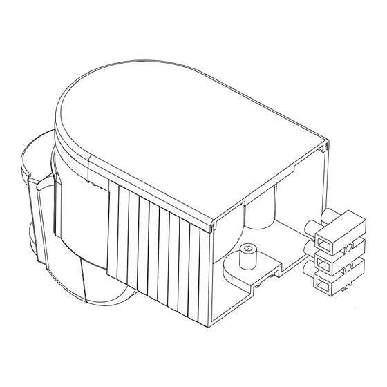
Fitting The Unit (Referring to the above figure)
Before commencing any electrical work, ensure mains supply cables are isolated by switching off and removing the relevant
Brown (Power Cable)
Blue(Lamp Wire)
Blue(Power Cable)
Black(Lamp Wire)
MODEL: SL180N / SL180BN
INSTALLATION AND OPERATING INSTRUCTIONS
FOR STAND-ALONE PIR DETECTOR
L
N
LS
2
. The SL180N/SL180BN SHOULD BE INSTALLED BY
Brown(PIR Wire)
Blue(PIR Wire)
Black(PIR Wire)
SL180N SL180BN Instructions Rev02
Advertisement
Table of Contents

Related Manuals for Challenger SL180N


Summary of Contents for Challenger SL180N
- Page 1 IMPORTANT: Never modify the sensor as there are no user serviceable parts inside. Not suitable for use with dimmer switches. Install in accordance with I.E.C. Wiring Regulations(Rigid Cable 0.75~1.50mm . The SL180N/SL180BN SHOULD BE INSTALLED BY A QUALIFIED ELECTRICIAN. Please pay attention to the following: Before commencing any electrical work, ensure the mains supply is isolated by switching off and removing the relevant fuse.
- Page 2 Walk-Test by placing the LUX control to day position ( ) and the TIME control to minimum (-). Once the SL180N/SL180BN sensor receives a valid trigger signal (such as movement of a human body or heat) within its detection area, the lamp(s) (load) will be turned on for the pre-set period of time.
- Page 3 Due to our policy of continuous improvement we reserve the right to change specification without prior notice. Errors and omissions excepted. These instructions have been carefully checked prior to publication. However, no responsibility can be accepted by Challenger Security Products for any misinterpretation of these instructions.
Need help?
Do you have a question about the SL180N and is the answer not in the manual?
Questions and answers