Epson fx-2180 Service Manual
9 pin impact do printer
Hide thumbs
Also See for fx-2180:
- User manual (227 pages) ,
- Manual (17 pages) ,
- Quick reference manual (16 pages)
Table of Contents
Advertisement
Quick Links
Advertisement
Table of Contents
Troubleshooting

Related Manuals for Epson fx-2180


Summary of Contents for Epson fx-2180
- Page 1 EPSON EPSON FX-2180 EPSON France S.A. SERVICE MANUAL...
- Page 2 EPSON FX-2180 ® 4009047...
- Page 3 The contents of this manual are subject to change without notice. All effort have been made to ensure the accuracy of the contents of this manual. However, should any errors be deteced, SEIKO EPSON would greatly appreciate being informed of them.
- Page 4 2. MAKE CERTAIN THAT THE SOURCE VOLTAGES IS THE SAME AS THE RATED VOLTAGE, LISTED ON THE SERIAL NUMBER/RATING PLATE. IF THE EPSON PRODUCT HAS A PRIMARY AC RATING DIFFERENT FROM AVAILABLE POWER SOURCE, DO NOT CONNECT IT TO THE POWER SOURCE.
- Page 5 PREFACE This manual describes basic functions, theory of electrical and mechanical operations, maintenance and repair procedures of FX-2180. The instructions and procedures included herein are intended for the experienced repair technicians, and attention should be given to the precautions on the preceding page. The chapters are organized as follows: CHAPTER 1.
- Page 6 REVISION STATUS Rev. Date Page(s) Contents 1998/04/02 First release...
-
Page 7: Table Of Contents
TABLE OF CONTENTS PRODUCT DESCRIPTIONS 1.1 SPECIFICATIONS .................................1-1 1.2 OPERATION..................................1-8 1.2.1 Control Panel Operation..................................1-8 1.2.1.1 Switches ....................................1-8 1.2.1.2 Lamps .......................................1-9 1.2.2 Buzzer ........................................1-9 1.3 SPECIAL FUNCTION ..............................1-10 1.3.1 Operation at power on..................................1-10 1.3.1.1 Self Test ....................................1-10 1.3.1.2 Default Setting..................................1-10 1.3.1.3 Data Dump ....................................1-11 1.3.1.4 Clear EEPROM ..................................1-11 1.3.1.5 Clear EEPROM for driving line counter for ribbon changing timing..................1-11... - Page 8 2.1.2 Power Supply Circuit..................................2-2 2.1.2.1 Power Supply Overview ................................2-2 2.1.3 Control Circuit.....................................2-3 2.1.3.1 Overview of Control Circuit Operation ............................2-3 TROUBLESHOOTING 3.1 OVERVIEW..................................3-1 3.2 TROUBLESHOOTING INFORMATION.........................3-1 3.2.1 Printhead ......................................3-1 3.2.2 Detectors ......................................3-2 3.2.3 Motors........................................3-3 3.2.4 Error Codes with Indications and Buzzer............................3-3 3.3 UNIT LEVEL TROUBLESHOOTING ....................
- Page 9 4.2.2 Removing the Panel Board Assembly ..............................4-6 4.2.3 Removing the Printhead..................................4-7 4.2.4 Removing the HP Sensor ...................................4-8 4.2.5 Removing the PW Sensor Assembly ..............................4-9 4.2.6 Removing the Platen Assembly...............................4-10 4.2.7 Removing the Upper Housing Assembly............................4-11 4.2.8 Removing the Case Open Sensor Assembly..........................4-12 4.2.9 Removing the Printer Mechanism ..............................4-13 4.2.9.1 Removing the CR Motor Assembly ............................4-14 4.2.9.2 Removing the PF Motor ................................4-15...
- Page 10 ADJUSTMENT 5.1 ADJUSTMENT OVERVIEW............................5-1 5.1.1 Required Adjustment..................................5-1 5.1.2 Required Adjustment Tools ................................5-1 5.2 ADJUSTMENT AND RESETTING..........................5-2 5.2.1 Platen Gap Adjustment ..................................5-2 5.2.2 Bi-directional Print Alignment (Bi-d) Adjustment..........................5-4 5.2.2.1 Bi-d Adjustment using the Setting Diskette ..........................5-4 5.2.2.2 Bi-D Adjustment from the Control Panel ...........................5-6 5.2.3 Factory Settings....................................5-7 5.2.4 TPE Level Reset....................................5-8 MAINTENANCE...
-
Page 11: Product Descriptions
PRODUCT DESCRIPTIONS... -
Page 12: Specifications
FX-2180 Service Manual Product Descriptions 1.1 SPECIFICATIONS RESOLUTION Table 1-2. Resolution This printer is based on FX-2170. The printing speed and copy ability and etc., are increased than that. So, almost main components of this printer is Printing mode Horizontal... - Page 13 FX-2180 Service Manual Product Descriptions Table 1-3. Printable Area (Cut Sheet) Continuous paper Single sheet Multi part Width (PW) Refer to Paper / Media Refer to Paper / Media Length (PL) Refer to Paper / Media Refer to Paper / Media...
- Page 14 FX-2180 Service Manual Product Descriptions Roll paper Paper path Manual insertion Front / Rear in , Top out Rear in, Top out Tractor Front / Rear / bottom in, Top out Feed speed Normal 61ms (1/6inch feed) 0.127MPS or 5.0IPS...
- Page 15 FX-2180 Service Manual Product Descriptions Multi part Table 1-9. Paper Specification (Multi part sheet) Table 1-8. Paper Specification (Multi part sheet) Front entry Rear entry Min. Max. Minimum Maximum Front entry Rear entry Envelope Width (inch) Minimum Maximum Minimum Maximum No.
- Page 16 FX-2180 Service Manual Product Descriptions Continuous paper Continuous paper with labels Table 1-10. Paper Specification (Continuous paper) Table 1-11. Paper Specification (Continuous paper with Labels) Front entry Rear entry Bottom entry Front entry Rear entry Bottom entry Min. Max. Min.
- Page 17 FX-2180 Service Manual Product Descriptions Roll paper ELECTRICAL SPECIFICATION Table 1-12. Paper Specification (Multi part sheet) 120V version Front entry Rear entry Rated voltage AC120V Min. Max. Minimum Maximum Input voltage range AC 99 - 132V Rated frequency range...
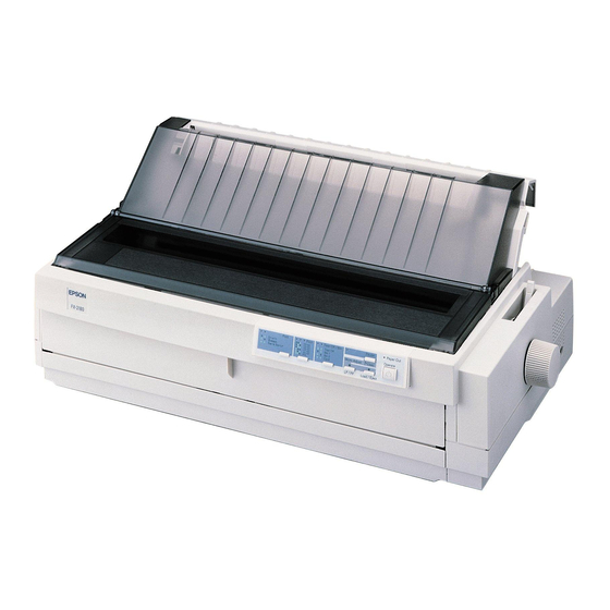
- Page 18 AS/NZS 3548 class B UPS version Safety standard UL1950 CSA C22.2 No.950 EN60950 (TÜV, NEMKO) FCC part 15 subpart B class B CSA C108.8 class B EN55022(CISPR pub.22) class B AS/NZS 3548 class B Figure 1-5. Exterior View of the FX-2180 Rev. A...
-
Page 19: Operation
FX-2180 Service Manual Product Descriptions 1.2.1.1 Switches 1.2 OPERATION Operate This switch turns the printer on / off. It is set in the secondary circuit of This section describes user operation. the power supply board. 1.2.1 Control Panel Operation WARNING As this operate switch is secondary switch, the This printer’s operation panel contains seven switches and nine LED lamps,... -
Page 20: Lamps
FX-2180 Service Manual Product Descriptions 1.2.2 Buzzer Micro Adjust ↑ / ↓ This printer makes buzzer sounds when it discover error or illegal condition, These switches are effective when the micro adjust function is enable as listed below: by Pause switch. -
Page 21: Special Function
FX-2180 Service Manual Product Descriptions 1.3 SPECIAL FUNCTION START Holding down Pitch This printer provides the special functions to extend the printer abilities for switch, turn on. customers as followings, Pitch switch selects 1.3.1 Operation at power on Main menu. -
Page 22: Data Dump
Item Factory Setting Value line count, driving hour, driving line counter for ribbon changing timing, Character Table Standard version: PC437 starting year, starting month and starting date. (Refer to the FX-2180 NLSP version: PC437 Specifications.) International character Italic U.S.A CAUTION... -
Page 23: Bi-D Adjustment
FX-2180 Service Manual Product Descriptions 1.4 CONSUMABLES & OPTIONS 1.3.1.7 Bi-D Adjustment Using this function, the customer can performs Bi-directional adjustment easily. 1.4.1 Consumables Adjusting Method Ribbon cartridge S015086 The setting method is shown in the flowchart as following, Ribbon pack S010033 1.4.2 Options... -
Page 24: Operating Principles
OPERATING PRINCIPLES... -
Page 25: Overview
FX-2180 Service Manual Operating Principles 2.1 OVERVIEW Rear Tractor This printer consists of the printer mechanism, the power supply circuit, the Disengage Gear 1 control circuit, operation panel, housing and etc,. The operating principles of main components are described in this chapter as followings;... -
Page 26: Power Supply Circuit
FX-2180 Service Manual Operating Principles circuit composed of an ZC-RCC (zero cross ringing choke converter), it 2.1.2 Power Supply Circuit realizes to the circuit high stability, efficiency and portability. This printer can be powered between three power supply boards: the This circuit provides the power switch (operate switch) in the secondary C166PSB(120V), C166PSE(220-240V) and C244PSH(120V/220-240V). -
Page 27: Control Circuit
FX-2180 Service Manual Operating Principles The functions of main components of control circuit on C244MAIN board are 2.1.3 Control Circuit shown on the following table. The control circuit consists of C244MAIN control board and the operation Table 2-3. Functions of Main Components panel board. -
Page 28: Troubleshooting
TROUBLESHOOTING... -
Page 29: Overview
FX-2180 Service Manual Troubleshooting 3.1 OVERVIEW This chapter contains flowcharts and check point tables that are helpful for troubleshooting the printer. The flowcharts facilitate identifying faulty units or parts from abnormal symptoms. The checkpoints provides unit characteristics, such as resistance, continuity, and so on, to which you can refer when isolating faulty units or parts. -
Page 30: Detectors
FX-2180 Service Manual Troubleshooting 3.2.2 Detectors Table 3-2. Detector Test Point Table 3-3. Detector Test Point (continue.) Detector Test Method Meter Detector Test Method Meter Test Pin No. Test Pin No. CN No. (Set Meter to DC Voltage) Reading CN No. -
Page 31: Motors
FX-2180 Service Manual Troubleshooting 3.2.3 Motors 3.2.4 Error Codes with Indications and Buzzer Table 3-4. Motor Test Point Table 3-5. Error Codes with Indications and Buzzer PF Motor Indicators Motor connector No. CN10 Error Paper Tear Buzzer* Pause Pitch Font ... -
Page 32: Unit Level Troubleshooting
FX-2180 Service Manual Troubleshooting 1. Abnormal CR Operation 3.3 UNIT LEVEL TROUBLESHOOTING START You may be able to identify the defective unit just from the symptom displayed. The table below provides the symptoms for a number of Dose the CR motor... - Page 33 FX-2180 Service Manual Troubleshooting 2. Abnormal Paper Feed Operation - 1 2. Abnormal Paper Feed Operation - 2 START START Is CN10 Is cut sheet loaded Dose PF motor Connect CN10 correctly. connected Is paper ejected correctly, but rotate? correctly?
-
Page 34: Abnormal Printing
FX-2180 Service Manual Troubleshooting 3. Abnormal Control Panel Operation 4. Abnormal Printing START START Check the data from host Is the self-test Dose the operate Check the Operation PC using Hex dump printed button turn on or button on the operation function. -
Page 35: Repairing The Power Supply Board
FX-2180 Service Manual Troubleshooting Table 3-8. Repairing the Power Supply Board (Continued.) 3.4 REPAIRING THE POWER SUPPLY BOARD Problem Cause Checkpoint Solution This section provides instructions for repairing a defective power supply • Check the resistance between +35V Switch- Replace board assembly. - Page 36 FX-2180 Service Manual Troubleshooting Table 3-9. Repairing the Power Supply Board (Continued.) Problem Cause Checkpoint Solution +5V lines Chopper Check the waveform at pin 8 of Replace is not IC IC51 is IC51. IC51. output. failure. Figure 3-10. Waveform 3...
-
Page 37: Repairing C244 Main Board Assembly
FX-2180 Service Manual Troubleshooting Table 3-11. Repairing C244 MAIN Board Assembly (Continued.) 3.5 REPAIRING C244 MAIN BOARD ASSEMBLY Problem Cause Checkpoint Solution This section provides instructions for repairing C244 MAIN board Check the signal for a change Replace the assembly. It describes various problem, symptoms, likely cases and... - Page 38 FX-2180 Service Manual Troubleshooting Table 3-12. Repairing C244 MAIN Board Assembly (Continued.) Table 3-13. Repairing C244 MAIN Board Assembly (Continued.) Problem Cause Checkpoint Solution Problem Cause Checkpoint Solution • Check the input signal • If the input • Check the input signal •...
- Page 39 FX-2180 Service Manual Troubleshooting Table 3-14. Repairing C244 MAIN Board Assembly (Continued.) Problem Cause Checkpoint Solution • Check the input signal • If the input IC1 or particular head drive waveform (CH 1) at BASE of signal is not dot fails transistor each transistor.
-
Page 40: Repairing The Printer Mechanism
FX-2180 Service Manual Troubleshooting 3.6 REPAIRING THE PRINTER MECHANISM Table 3-16. Repairing the Printer Mechanism (Continued.) This section provides instructions for repairing the printer mechanism. It Problem Symptom Cause Checkpoint Solution describes various symptoms, likely causes, checkpoints and solutions. The −... - Page 41 FX-2180 Service Manual Troubleshooting Table 3-17. Repairing the Printer Mechanism (Continued.) Table 3-18. Repairing the Printer Mechanism (Continued.) Problem Symptom Cause Checkpoint Solution Problem Symptom Cause Checkpoint Solution Printer is No image is Common Check the Replace Paper PF motor dose...
- Page 42 FX-2180 Service Manual Troubleshooting Table 3-19. Repairing the Printer Mechanism (Continued.) Table 3-20. Repairing the Printer Mechanism (Continued.) Problem Symptom Cause Checkpoint Solution Problem Symptom Cause Checkpoint Solution Paper Paper is only A foreign Once remove Remove Paper Cut sheet...
-
Page 43: Disassembly And Assembly
DISASSEMBLY AND ASSEMBLY... -
Page 44: Overview
FX-2180 Service Manual Disassembly and Assembly 4.1 OVERVIEW 4.1.2 Tools The following tables list the tools recommended for disassembling, This section describes various points to note when disassembling and assembling, or adjusting the printer. Use only tools that meet these assembling the printer. -
Page 45: Service Check After Repair
FX-2180 Service Manual Disassembly and Assembly 4.1.3 Service Check After Repair Before returning the printer after service, use the check list in the following table, which provides a record to make servicing and shipping more efficient. Table 4-3. Inspection Check List for the Repaired Printer (1) Table 4-4. -
Page 46: Specifications For Screws
FX-2180 Service Manual Disassembly and Assembly 4.1.4 Specifications for Screws Table 4-6. Screw types The following table lists the abbreviations used in the following sections for small parts, such as screws and washers, etc. Head Table 4-5. Screw types and Abbreviations... -
Page 47: Disassembly And Assembly
FX-2180 Service Manual Disassembly and Assembly 4.2 DISASSEMBLY AND ASSEMBLY The flowchart below shows the order to disassemble the printer. START This section describes procedures for disassembling and assembling the main components of the printer. When the procedure for installing a... -
Page 48: Preparation For Disassembly The Printer
FX-2180 Service Manual Disassembly and Assembly 4.2.1 Preparation for Disassembly the Printer Remove the following belonging parts from the printer: Front edge guide assembly, Front cover, Bottom cover, Rear edge guide assembly, Printer cover, Paper eject assembly, Front / rear tractor assembly, Ribbon cartridge... -
Page 49: Removing The Panel Board Assembly
FX-2180 Service Manual Disassembly and Assembly 4.2.2 Removing the Panel Board Assembly Remove the printer cover and ribbon cartridge. (Refer to Section 4.2.1.) CHECK POINT Before disconnecting the FFC from CN1, slide Release the left clips for the panel board assembly by pushing them the lock cover for CN1 as shown in Figure 4-4, from the cutout located on side front of the upper housing assembly. -
Page 50: Removing The Printhead
FX-2180 Service Manual Disassembly and Assembly 4.2.3 Removing the Printhead Remove the printer cover and ribbon cartridge. (Refer to Section 4.2.1.) CHECK POINT The FFC must be connected properly, as shown Remove two CBS screws (3 × 10)securing the printhead to the CR in the following figure. -
Page 51: Removing The Hp Sensor
FX-2180 Service Manual Disassembly and Assembly 4.2.4 Removing the HP Sensor Remove the printer cover, ribbon cartridge, front edge guide and front cover. (Refer to Section 4.2.1.) Disconnect the connector cable for the HP sensor. Remove the HP sensor by pushing up and releasing the 2 clips at the bottom of the HP sensor from the front paper entrance. -
Page 52: Removing The Pw Sensor Assembly
FX-2180 Service Manual Disassembly and Assembly 4.2.5 Removing the PW Sensor Assembly CHECK POINT Mount the PW sensor assembly onto the ribbon Remove the printer cover and ribbon cartridge. (Refer to Section 4.2.1.) mask holder groove, aligning the bottom line of Remove the CB screw (2.5×5) securing the PW sensor to the ribbon... -
Page 53: Removing The Platen Assembly
FX-2180 Service Manual Disassembly and Assembly 4.2.6 Removing the Platen Assembly Remove the printer cover, ribbon cartridge and platen knob. (Refer to Section 4.2.1.) Set the release lever to pull tractor feed mode. Release both locks for the left and right bushing (8mm) by pushing the lever holder for the bushings outside, and then pulling the holder lever forward. -
Page 54: Removing The Upper Housing Assembly
FX-2180 Service Manual Disassembly and Assembly 4.2.7 Removing the Upper Housing Assembly Remove the printer cover, rear edge guide assembly paper eject assembly and rear tractor unit. (Refer to Section 4.2.1.) Remove the panel board assembly. (Refer to Section 4.2.2.) Remove four CBB screws (4 ×... -
Page 55: Removing The Case Open Sensor Assembly
FX-2180 Service Manual Disassembly and Assembly 4.2.8 Removing the Case Open Sensor Assembly Remove the printer cover, rear edge guide assembly, paper eject assembly and rear tractor unit. (Refer to Section 4.2.1.) Remove the panel board assembly. (Refer to Section 4.2.2.) Turn the upper housing assembly over and remove the case open sensor assembly by loosening one CBB screw (3 ×... -
Page 56: Removing The Printer Mechanism
FX-2180 Service Manual Disassembly and Assembly 4.2.9 Removing the Printer Mechanism Remove the printer cover, the rear / front edge guide assemblies, front cover, paper eject assembly, and rear tractor unit. (Refer to Section 4.2.1.) Remove the panel board assembly. (Refer to Section 4.2.2.) Remove the upper housing assembly. -
Page 57: Removing The Cr Motor Assembly
FX-2180 Service Manual Disassembly and Assembly 4.2.9.1 Removing the CR Motor Assembly Remove the printer cover, rear edge guide assembly, paper eject CHECK POINT The tightening torque for the 2 CR Mounting assembly and rear tractor unit. (Refer to Section 4.2.1.) screws : 0.78 ∼... -
Page 58: Removing The Pf Motor
FX-2180 Service Manual Disassembly and Assembly 4.2.9.2 Removing the PF Motor Remove the printer cover, the rear / front edge guide assemblies, front cover, paper eject assembly, and rear / fronts tractor units. (Refer to Section 4.2.1.) Remove the panel board assembly. (Refer to Section 4.2.2.) Remove the upper housing assembly. -
Page 59: Removing The Pg Sensor Assembly
FX-2180 Service Manual Disassembly and Assembly 4.2.9.3 Removing the PG Sensor Assembly CHECK POINT When the sensors are mounted to the PG sensor Remove the printer cover, the rear / front edge guide assemblies, front holder be sure to mount the while connector’s cover, paper eject assembly, and rear / fronts tractor units. -
Page 60: Removing The Right Frame Assembly
FX-2180 Service Manual Disassembly and Assembly 4.2.9.4 Removing the Right Frame Assembly $'-8670(17 Adjust the platen gap and Bi-directional print Remove the printer cover, the rear / front edge guide assemblies, front alignment. (Refer to Chapter 5.) cover, paper eject assembly, and rear / fronts tractor units. (Refer to Section 4.2.1.) -
Page 61: Disassembling The Right Frame Assembly
FX-2180 Service Manual Disassembly and Assembly 4.2.9.5 Disassembling the Right Frame Assembly Remove one CBS screw (3 × 6) and one CBS screw (3 × 8) securing the right sub frame. (The bold line in the illustration is the right sub frame.) - Page 62 FX-2180 Service Manual Disassembly and Assembly CHECK POINT Notice how the intermittent gear, release lever, and release transmission lever are engaged. When engage the release lever and release transmission lever to the tractor clutch cam, notice the points in the following figure.
-
Page 63: Removing The Left Frame Assembly
FX-2180 Service Manual Disassembly and Assembly 4.2.9.6 Removing the Left Frame Assembly Remove the printer cover, the rear / front edge guide assemblies, front cover, paper eject assembly, and rear / fronts tractor units. (Refer to Section 4.2.1.) Remove the panel board assembly. (Refer to Section 4.2.2.) Remove the upper housing assembly. -
Page 64: Removing The Ribbon Drive (Rd) Assembly
FX-2180 Service Manual Disassembly and Assembly 4.2.9.7 Removing the Ribbon Drive (RD) Assembly The tightening torque for the CBS screws (3 × × 8) CHECK POINT Remove the printer cover, the rear / front edge guide assemblies, front : 0.78 ∼ ∼ 0.98 Nm (8 ∼ ∼ 10 Kgf-cm) cover, paper eject assembly, and rear / fronts tractor units. -
Page 65: Removing The Cr Assembly
FX-2180 Service Manual Disassembly and Assembly 4.2.9.8 Removing the CR Assembly Remove the printer cover, the rear / front edge guide assemblies, front cover, paper eject assembly, and rear / fronts tractor units. (Refer to Section 4.2.1.) Remove the panel board assembly. (Refer to Section 4.2.2.) Remove the upper housing assembly. - Page 66 FX-2180 Service Manual Disassembly and Assembly CHECK POINT CHECK POINT Insert the 2 oil pads into the proper position in the If remove the rear CR guide shaft along the CR CR assembly, as shown in the following figure; assembly once, be sure to reinstall the rear CR guide shaft in the printer mechanism.
-
Page 67: Removing The Rear Pe Sensor Assembly
FX-2180 Service Manual Disassembly and Assembly 4.2.9.9 Removing the Rear PE Sensor Assembly 4.2.9.10 Removing the Front PE Sensor Assembly Remove the printer cover, the rear / front edge guide assemblies, front Remove the printer cover, the rear / front edge guide assemblies, front cover, paper eject assembly, and rear / fronts tractor units. -
Page 68: Removing The Main Board Assembly
FX-2180 Service Manual Disassembly and Assembly 4.2.9.11 Removing the Main Board Assembly Remove the printer cover, the rear / front edge guide assemblies, front cover, paper eject assembly, and rear / fronts tractor units. (Refer to Section 4.2.1.) Remove the panel board assembly. (Refer to Section 4.2.2.) Remove the upper housing assembly. -
Page 69: Removing The Power Supply Board Assembly
FX-2180 Service Manual Disassembly and Assembly 4.2.9.12 Removing the Power Supply board Assembly CHECK POINT Insert the cable for CN2 on the power supply Remove the printer cover, the rear / front edge guide assemblies, front board under the fan motor. -
Page 70: Disassembly And Assembly Of Csf Bin 1
FX-2180 Service Manual Disassembly and Assembly 4.2.10 Disassembly and Assembly of CSF Bin 1 This section describes procedure for disassembling and assembling the operational cut sheet feeder. In general, you can install a component in the CSF simply by reversing the procedure for removing. Therefore, this section dose not describe assembly procedures in most cases. -
Page 71: Disassembling Paper Support Block Assembly
FX-2180 Service Manual Disassembly and Assembly 4.2.10.2 Disassembling Paper Support Block Assembly Remove one CSF tight (3 × 8) screw securing the paper support shaft Remove the CSF gear cover. (Refer to Section 4.2.10.1.) to the right CSF frame, as shown in the following figure. - Page 72 FX-2180 Service Manual Disassembly and Assembly Figure 4-43. Removing the Paper Loading Roller Cover Assembly 10. Remove the paper support shaft by pulling it toward the right or left side. 11. Remove the paper holder spring. CHECK POINT Be sure to assemble the paper feed roller into the proper side.
-
Page 73: Removing The Paper Eject Assembly Cover
FX-2180 Service Manual Disassembly and Assembly 4.2.10.3 Removing the Paper Eject Assembly Cover Remove the paper assembly cover by releasing two clips located along both edges of the paper eject assembly cover, as shown in the following figure. Figure 4-44. Removing the Paper Eject Assembly Cover Figure 4-45. -
Page 74: Disassembly And Assembly Of Csf Bin 2
FX-2180 Service Manual Disassembly and Assembly 4.2.11 Disassembly and Assembly of CSF Bin 2 Remove the following 5 gears and the spring from the CSF frame. 4.2.11.1 Disassembling the Right Side Block Remove the gear train cover by releasing the four clips shown in the following figure. -
Page 75: Disassembling The Paper Support Block Assembly
FX-2180 Service Manual Disassembly and Assembly 4.2.11.2 Disassembling the Paper Support Block Assembly Remove the E-ring fixing the paper feed roller shaft to the right CSF frame. Remove two CTBS (3 × 8) screws securing the paper support shaft to both right and left CSF frame. - Page 76 ADJUSTMENT...
-
Page 77: Adjustment
FX-2180 Service Manual Adjustment 5.1 ADJUSTMENT OVERVIEW CHECK POINT When any part is replaced or reassembled, use the Check Program included on the Settings Diskette 5.1.1 Required Adjustment to check the performance and settings of various check pattern. This section describes what adjustments are required after any part is removed or replaced. -
Page 78: Adjustment And Resetting
FX-2180 Service Manual Adjustment 5.2 ADJUSTMENT AND RESETTING 5.2.1 Platen Gap Adjustment PG SW1 If you have rotated or reassembled the rear CR guide shaft or parallelism adjustment bushing, or if printing is too light or too dark, even at the proper PG lever position, perform this adjustment at 3 positions : left end column, center column and right end column. - Page 79 FX-2180 Service Manual Adjustment Drilled Hole Figure 5-3. Platen Gap Adjusting 10. When the gap is correct at the 5 column, check the platen gap at the center column, and then the right edge column position. 11. If the platen gap is wider at the left edge column than right edge column, adjust the parallelism for rear CR guide shaft by moving the parallelism adjustment bushing backward.
-
Page 80: Bi-Directional Print Alignment (Bi-D) Adjustment
FX-2180 Service Manual Adjustment 5.2.2 Bi-directional Print Alignment (Bi-d) Adjustment Program : J****** Setting : ****** 9 pins VR 0 = 0 VR 1 = 0 VR 2 = 0 This section describes the procedure for adjustment the bi-directional print alignment, required after mechanism repair. - Page 81 FX-2180 Service Manual Adjustment Highlight Bi-d Adjust by moving the cursor with ↑ or ↓ key and select it by pressing ENTER. CHECK POINT The adjusted value is not stored in the EEPROM After select Bi-D Adjust, the display shows the Bi-D Adjustment Menu until the printer power off, so you must once as following figure.
-
Page 82: Bi-D Adjustment From The Control Panel
FX-2180 Service Manual Adjustment 5.2.2.2 Bi-D Adjustment from the Control Panel Turn the printer on while pressing the PAUSE button to put the printer into Bi-d adjustment mode. The printer print out a guide sheet, containing 25 patterns in Super Draft mode. -
Page 83: Factory Settings
FX-2180 Service Manual Adjustment 5.2.3 Factory Settings In the menu, highlight the factory settings for the printer’s destination by This section describes the procedure to reset factory settings, which is moving the cursor with ↑ or ↓ key, and select the destination factory necessary if the main board is replaced. -
Page 84: Tpe Level Reset
FX-2180 Service Manual Adjustment 5.2.4 TPE Level Reset In the menu, highlight the factory settings for the printer’s destination by This section describes the procedure to reset the TPE (top paper end) level. moving the cursor with ↑ or ↓ key, and select the destination factory This operation is required when the PW sensor assembly is replaced, and if settings by pressing ENTER referring the Table 5-3. - Page 85 FX-2180 Service Manual Adjustment 10. In the menu, highlight TPE Adjust by moving the cursor with ↑ or ↓ key, and select it by pressing ENTER. CHECK POINT The adjusted value is not stored in the EEPROM 11. Set an A4 size sheet in the portrait direction from the rear paper guide until the printer power off, so you must once on the printer.
- Page 86 MAINTENANCE...
-
Page 87: Preventive Maintenance
The side of shaft in RD About the size G-26 are EPSON G-26 and O-2, which have been tested extensively and found to Ratchet of a grain of comply with the needs of this printer. (Table 6-1 provides details about these rice lubrications.) Before applying a lubricant, be sure the surface to be... - Page 88 FX-2180 Service Manual Maintenance Spur Gear 34.5 Gap Adjustment Lever Spur Gear 34.5 Platen Gap Adjustment Slot RD Ratchet Figure 6-1. Lubrication points - 1 Rear Frame Figure 6-2. Lubrication points - 2 Rev. A...
-
Page 89: Appendix
APPENDIX... -
Page 90: Connector Summary
FX-2180 Service Manual Appendix Table 7-1. Connector Summary 7.1 CONNECTOR SUMMARY Board Connector Function Pins Main Board Parallel Interface The following figure shows the connector connections of main components. Assy. And, the following table shows the summary of function s and sizes of the TYPE-B Interface connectors. - Page 91 FX-2180 Service Manual Appendix Table 7-7. Connector Pin Alignments - CN8 Table 7-3. Connector Pin Alignments - CN4 Signal Name Function Signal Name Function Not connected CR Home position signal Head data 1 Signal Ground Head data 9 ...
- Page 92 FX-2180 Service Manual Appendix Table 7-11. Connector Pin Alignments - CN12 Table 7-8. Connector Pin Alignments - CN9 Signal Name Function Signal Name Function RELEASE1 Release sensor 1 signal Head data 3 Signal Ground Not connected RELEASE2 Release sensor 2 signal ...
- Page 93 FX-2180 Service Manual Appendix Table 7-14. Connector Pin Alignments - CN15 Signal Name Function COPEN Case open sensor signal PAUSE Pause LED signal +5VDC POUTL Paper out LED signal RESRVL Pitch select LED signal PAUSSW Pause button signal TMIN2L...
-
Page 94: Circuit Board Component Layout
FX-2180 Service Manual Appendix 7.2 CIRCUIT BOARD COMPONENT LAYOUT Figure 7-3. . C244 MAIN Board Assembly Component Layout (2) Figure 7-2. C244 MAIN Board Assembly Component Layout (1) Rev. A... - Page 95 FX-2180 Service Manual Appendix Figure 7-5. C166 PSE Board Assembly Component Layout Figure 7-4. C166 PSB Board Assembly Component Layout Rev. A...
-
Page 96: Exploded Diagrams
FX-2180 Service Manual Appendix 7.3 EXPLODED DIAGRAMS See the following 3 pages for the exploded diagrams for FX-2180. Rev. A... - Page 97 113 127 EXPLODED DIAGRAM FOR FX-2180(1)
- Page 98 637 595 EXPLODED DIAGRAM FOR FX-2180(2)
- Page 99 EXPLODED DIAGRAM FOR FX-2180(3)
-
Page 100: Circuit Board Diagrams
FX-2180 Service Manual Appendix 7.4 CIRCUIT BOARD DIAGRAMS See the following pages for the circuit diagrams below: • C244 MAIN • C166 PSB • C166 PSE • C244 PSH Rev. A 7-11... - Page 102 1SS120 DTA113ZSA TLP521-2 DTC124GSA 0.22u 1.5K 1M/0.5W 270K 3.6K 3.15A/125V 4 IC52B NJM2903D B2P3-VH B2P3-VH * : Heat sink (Q1,D51) : CN3 is not mounted. Model : FX-2180 Board : C166PSB BOARD Sheet : 1 of 1 Rev. : B...
- Page 103 D 8 6 R 8 2 1 S S 1 2 0 R 5 9 R 6 0 4 . 7 5 K 1 % 4 . 7 K R 5 8 2 0 0 K L 5 1 R 8 1 C 5 9 H C D - 6 4 7 1 H S D B 1...
Need help?
Do you have a question about the fx-2180 and is the answer not in the manual?
Questions and answers