
Related Manuals for MTU MS150112/01E


Summary of Contents for MTU MS150112/01E
-
Page 1: Operating Instructions
Operating Instructions Diesel engine 12V 4000 C64 Application group 5B MS150112/01E... - Page 2 All information in this publication was the latest information available at the time of going to print. MTU Friedrichshafen GmbH reserves the right to change, delete or supplement the information provided as and when required.
-
Page 3: Table Of Contents
7.12.3 EGR cooler ‒ Check 6.3 Fault messages of Engine Control Unit ECU 7.12.4 Exhaust flaps – Overview 9 for Series 4000 7.12.5 Exhaust flaps – Actuator function check 7.12.6 Exhaust flaps – Overview MS150112/01E 2014-10 | Table of Contents | 3... - Page 4 8.2 MTU contact persons/service partners 7.17.3 Charge-air coolant – Draining 7.17.4 Charge-air coolant – Filling 9 Appendix B 7.17.5 Checking charge-air coolant pump pressure relief port 9.1 Special Tools 7.18 Belt Drive 9.2 Index 4 | Table of Contents | MS150112/01E 2014-10...
-
Page 5: Safety
• With fluids and lubricants approved by the manufacturer in accordance with the (→ Fluids and Lubri- cants Specifications of the manufacturer) • With spare parts approved by the manufacturer in accordance with the (→ Spare Parts Catalog/MTU contact/Service partner) •... -
Page 6: Personnel And Organizational Requirements
Wear proper protective clothing for all work. When working, always wear the necessary personal protective equipment (e.g. ear protectors, protec- tive gloves, goggles, breathing protection). Observe the information on personal protective equipment in the respective activity description. 6 | Safety | MS150112/01E 2014-10... -
Page 7: Safety Requirements For Startup And Operation
• Mop up any leaked or spilled fluids and lubricants immediately or soak up with a suitable binding agent. Operation of electrical equipment Some components are live (high voltage) when electrical equipment is in operation. Observe the safety instructions for these appliances. MS150112/01E 2014-10 | Safety | 7... -
Page 8: Safety Requirements For Maintenance And Repair Work
Observe the cooling time for components which have been heated for installation or removal (risk of burning!). Always use suitable ladders and work platforms when working above head-height. Ensure that compo- nents or assemblies are placed on stable surfaces. 8 | Safety | MS150112/01E 2014-10... - Page 9 Do not place tools on the battery. Check polarity before connecting the cable to the battery. Battery polarity reversal may lead to injury by the sudden discharge of acid or bursting of the battery unit. MS150112/01E 2014-10 | Safety | 9...
- Page 10 700 nm), a maximum output of 5 mW, and in which the beam axis and surface are designed to pre- vent any risk to the eyes. Measuring component deviations Workpieces, components and measuring instruments are within specified tolerances at a reference temperature of 20°C. 10 | Safety | MS150112/01E 2014-10...
-
Page 11: Fire Prevention And Environmental Protection, Fluids And Lubricants, Auxiliary Materials
The latest version can be found on the website on the "Technical Info" or "Spare Parts and Service" tabs at http://www.mtu-online.com. Consumable fluids and materials may also be hazardous or toxic. When using fluids, lubricants, consum- ables and other chemical substances, follow the safety regulations that apply to the product. -
Page 12: Compressed Air
• After contact with skin, rinse affected parts of the body with plenty of water. • Rinse eyes immediately with eye drops or clean tap water. Seek medical attention as soon as possi- ble. 12 | Safety | MS150112/01E 2014-10... -
Page 13: Standards For Safety Notices In The Text
The higher level warning notice is used if several hazards apply at the same time. Warnings related to personal injury shall be considered to include a warning of potential damage. MS150112/01E 2014-10 | Safety | 13... -
Page 14: Transport
Place the engine/genset on a firm, flat surface only. Make sure that the consistency and load-bearing capacity of the ground or support surface is adequate. Never set an engine down on the oil pan unless expressively authorized to do so by MTU on a case-to- case basis. -
Page 15: General Information
(1) and letter "Bx" refers to the cylinders on the right-hand side (3). The cylinders of each bank are numbered consecutively, starting with x=1 at driving end (4). The numbering of other engine components also starts with 1 at driving end (4). MS150112/01E 2014-10 | General Information | 15... -
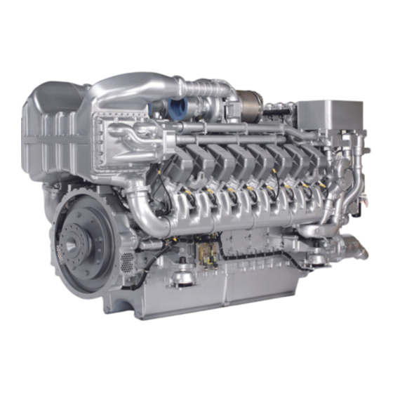
Page 16: Engine - Overview
10 Air intake Engine model designation Explanation of engine model designation 12 V 4000 C64 Number of cylinders Cylinder arrangement: V engine 4000 Series Application: Construction and Industrial, mobile Application segment: 6 Design index 16 | General Information | MS150112/01E 2014-10... -
Page 17: Sensors, Actuators And Injectors - Overview
2.3 Sensors, actuators and injectors – Overview 1 B13 - Crankshaft speed 3 F57 - Charge-air coolant 2 F70 - Water level in fuel level prefilter (external) 4 F33 - Engine coolant level MS150112/01E 2014-10 | General Information | 17... - Page 18 8 Y39.B1-B6 - Injectors B1- 4 B89 - Lambda The injectors (8) are underneath the cylinder head covers of the cylinders. Injector replacement and associated activities (→ Page 117). 18 | General Information | MS150112/01E 2014-10...
- Page 19 15 B4 - Exhaust temperature fore filter 10 B34.1 - Fuel pressure after filter The injectors (6) are underneath the cylinder head covers of the cylinders. Injector replacement and associated activities (→ Page 117). MS150112/01E 2014-10 | General Information | 19...
-
Page 20: Technical Data
Fuel temperature at engine inlet connection °C Fuel temperature at engine inlet connection, max (w/o power °C reduction) CONSUMPTION Number of cylinders Lube oil consumption after 100 h runtime (B = hourly fuel con- % of B sumption) 20 | Technical Data | MS150112/01E 2014-10... - Page 21 Number of cylinders Lube oil operating temperature before engine, from °C Lube oil operating temperature before engine, to °C Lube oil temperature before engine, alarm °C Lube oil temperature before engine, shutdown °C MS150112/01E 2014-10 | Technical Data | 21...
- Page 22 Oil pan capacity at dipstick mark “max.” (standard oil system) Liters (option: max. operating inclinations) WEIGHTS (basic design, dry engine) Number of cylinders Engine dry weight (with attached standard accessories, without 8200 coupling) 22 | Technical Data | MS150112/01E 2014-10...
- Page 23 Engine surface noise with attenuated intake noise (filter) - BL dB(A) (free-field sound-pressure level Lp, 1m distance, ISO 6798) Engine surface noise with attenuated intake noise (filter) - BL dB(A) (sound power level LW, ISO 6798) MS150112/01E 2014-10 | Technical Data | 23...
-
Page 24: Firing Order
3.2 Firing order Firing order Number of cylinders Firing order A1-B5-A5-B3-A3-B6-A6-B2-A2-B4-A4-B1 24 | Technical Data | MS150112/01E 2014-10... -
Page 25: Engine - Main Dimensions
3.3 Engine – Main dimensions Engine – Main dimensions Item Dimensions Length (A) approx. 2878 mm Width (B) approx. 1631 mm Height (C) approx. 2393 mm MS150112/01E 2014-10 | Technical Data | 25... -
Page 26: Operation
4.1 Putting the engine into operation after extended out-of-service periods (>3 months) Preconditions ☑Engine is stopped and starting disabled. ☑MTU Preservation and Represervation Specifications (A001070/..) are available. Putting the engine into operation after extended out-of-service periods (>3 months) Item Action Engine Depreserve (→... -
Page 27: Putting The Engine Into Operation After Scheduled Out-Of-Service-Period
Check engine coolant level (→ Page 162); Check charge-air coolant level (→ Page 172). Coolant circuit Heat coolant with coolant preheater (if available; see manufacturer's docu- mentation). Engine control system Put into operation (see manufacturer's documentation). MS150112/01E 2014-10 | Operation | 27... -
Page 28: Operational Checks
Drain water and contaminants via drain cock on fuel prefilter (if fitted, see manufacturer's documentation). Check service indicator at fuel prefilter (if fitted, see manufacturer's docu- mentation). Engine coolant pump Check relief bore (→ Page 170). Charge-air coolant pump Check relief bore (→ Page 180). 28 | Operation | MS150112/01E 2014-10... -
Page 29: Engine - Starting In Manual Mode
> 40 °C. 2. Press start button. on manufacturer). • Automatic starting procedure is performed. • Engine speed instrument indicates increasing speed. • After the starting sequence is completed, engine is running at idle speed. MS150112/01E 2014-10 | Operation | 29... -
Page 30: Engine - Stopping In Manual Mode
Preparation Item Measure Engine Operate engine at idling speed for approx. 5 minutes. Stop engine Item Measure Switch cabinet, operator Press stop button. station etc. (depending on • Automatic stopping sequence is executed. manufacturer) 30 | Operation | MS150112/01E 2014-10... -
Page 31: After Stopping The Engine
4.6 After stopping the engine Preconditions ☑MTU Preservation and Represervation Specifications (A001070/..) are available. NOTICE Coolant sensors may freeze if there is a risk of frost. Risk of sensor damage! • Protect sensors from frost. After stopping the engine Item... -
Page 32: Plant - Cleaning
Seal all openings in a suitable way. b) Remove coarse dirt. c) Spray on cleaner sparingly and leave it for 1 to 5 minutes. d) Use the high-pressure jet to remove the loosened dirt. e) Dry engine with compressed air. 32 | Operation | MS150112/01E 2014-10... -
Page 33: Maintenance
Enter parameters for drift correction (CDC) and coding for (→ Page 190) the injectors (IIG). W1735 Replace auxiliary PTO. (→ Page 102) W1817 Check clearance of coupling rod of EGR flaps and replace (→ Page 147) if necessary. (→ Page 149) MS150112/01E 2014-10 | Maintenance | 33... - Page 34 Maintenance tasks W1906 In case of valve clearance deviations, check valve depth. (→ Page 109) W1907 Check and clean EGR cooler. (→ Page 142) (→ Page 143) Table 2: Maintenance task reference table [QL1] 34 | Maintenance | MS150112/01E 2014-10...
-
Page 35: Troubleshooting
Engine does not reach rated speed Component Cause Measure Fuel supply Fuel prefilter clogged. Replace Easy-change fuel filter clogged. Replace (→ Page 123). Air supply Air filter clogged. Clean. Fuel injection equip- Injector faulty. Replace (→ Page 117). ment MS150112/01E 2014-10 | Troubleshooting | 35... - Page 36 White exhaust gas Component Cause Measure Engine Not at operating temperature. Run up to operating temperature. Fuel system Water in fuel. Check fuel system on fuel prefilter. Drain fuel prefilter. Intercooler Leaking Contact Service. 36 | Troubleshooting | MS150112/01E 2014-10...
-
Page 37: Fault Messages On The Sam Display (Optional)
Fault messages can also be caused by faulty sensors/actuators. If the fault cannot be corrected with the troubleshooting information provided in the following table, contact Service. Our Service will check sensors/actuators and replace them if necessary. The following fault codes may appear on the display: (→ Page 38). MS150112/01E 2014-10 | Troubleshooting | 37... -
Page 38: Fault Messages Of Engine Control Unit Ecu 9 For Series 4000
3. Contact Service. 6 – SS T-Charge Air ZKP-Number: 2.0121.932 Charge-air temperature too high (limit value 2) Red alarm – engine shutdown Cause Corrective action Intercooler not operating 1. Check intercooler. correctly. 2. Contact Service. 38 | Troubleshooting | MS150112/01E 2014-10... - Page 39 Lube oil pressure too low (limit value 2) Red alarm – engine shutdown Cause Corrective action Insufficient oil. 1. Check oil level, top up as necessary (→ Page 154). 2. Acknowledge alarm. 3. Restart engine (→ Page 29). 4. Contact Service. MS150112/01E 2014-10 | Troubleshooting | 39...
- Page 40 23 – LO Coolant Level ZKP-Number: 2.0152.921 Coolant level too low (limit value 1) Yellow alarm – warning Cause Corrective action u Check coolant level in expansion tank (→ Page 162). Leak in coolant circuit. 40 | Troubleshooting | MS150112/01E 2014-10...
- Page 41 ZKP-Number: 2.3011.931 Speed of primary turbocharger too high (limit value 1) Yellow alarm – warning Cause Corrective action Obstructed charge-air circuit or 1. Reduce power. fault in turbocharger. 2. Check air filter. 3. Contact Service. MS150112/01E 2014-10 | Troubleshooting | 41...
- Page 42 37 – SS ETC2 Overspeed ZKP-Number: 2.3013.912 Speed of 1st secondary turbocharger too high (limit value 2) Red alarm – engine shutdown Cause Corrective action u Contact Service. Obstructed charge-air circuit or fault in turbocharger. 42 | Troubleshooting | MS150112/01E 2014-10...
- Page 43 58 – SS P-Coolant ZKP-Number: 2.0101.922 Coolant pressure too low (limit value 2) Red alarm – engine shutdown or reduced injection quantity Cause Corrective action u Check coolant level (→ Page 162). Leak in coolant circuit. MS150112/01E 2014-10 | Troubleshooting | 43...
- Page 44 Crankcase pressure too high (limit value 2) Red alarm – engine shutdown Cause Corrective action Crankcase extraction system 1. Reduce power. obstructed or leaking. 2. Replace oil mist fine separator insert . 3. Contact Service. 44 | Troubleshooting | MS150112/01E 2014-10...
- Page 45 68 – SS T-Coolant ZKP-Number: 2.0120.932 Coolant temperature too high (limit value 2) Red alarm – engine shutdown Cause Corrective action u Check coolant circuit. Coolant circuit not operating correctly (e.g. damage, leaks, low coolant level). MS150112/01E 2014-10 | Troubleshooting | 45...
- Page 46 89 – SS Engine Speed too Low ZKP-Number: 2.2500.030 Engine speed too low Red alarm – engine shutdown Cause Corrective action Various causes possible. 1. Acknowledge alarm. 2. Observe additional messages. 3. Contact Service. 46 | Troubleshooting | MS150112/01E 2014-10...
- Page 47 ZKP-Number: 2.1090.921 Preheating temperature too low (limit value 1) Yellow alarm – warning Cause Corrective action Coolant temperature for engine 1. Check preheating unit. start too low because preheater 2. Contact Service. is not working. MS150112/01E 2014-10 | Troubleshooting | 47...
- Page 48 119 – LOLO ECU Supply Voltage ZKP-Number: 2.0140.922 Supply voltage too low (limit value 2) Red alarm – start terminated Cause Corrective action Supply voltage at engine 1. Check engine governor supply voltage. governor too low. 2. Contact Service. 48 | Troubleshooting | MS150112/01E 2014-10...
- Page 49 Yellow alarm – warning Cause Corrective action Connection to or communication 1. Check devices connected to CAN. with a node at CAN bus 2 has 2. Check wiring (→ Page 189). failed. 3. Contact Service. MS150112/01E 2014-10 | Troubleshooting | 49...
- Page 50 Yellow alarm – automatic changeover to CAN 2 Cause Corrective action Short circuit, massive 1. Check CAN bus for short circuit, rectify short circuit as interference or Baud rate required. incompatibility. 2. Check shielding, improve shielding if necessary. 3. Contact Service. 50 | Troubleshooting | MS150112/01E 2014-10...
- Page 51 Coolant temperature sensor 1. Check sensor and wiring (B6), replace as necessary faulty. (→ Page 189). Short circuit or wire break. 2. Fault is rectified when engine is restarted (→ Page 29). 3. Contact Service. MS150112/01E 2014-10 | Troubleshooting | 51...
- Page 52 Coolant pressure sensor of 1. Check sensor and wiring (B26), replace as necessary intercooler faulty. (→ Page 189). Short circuit or wire break. 2. Fault is rectified when engine is restarted (→ Page 29). 3. Contact Service. 52 | Troubleshooting | MS150112/01E 2014-10...
- Page 53 Lube oil pressure sensor faulty. 1. Check sensor and wiring (B5), replace as necessary Short circuit or wire break. (→ Page 189). 2. Fault is rectified when engine is restarted (→ Page 29). 3. Contact Service. MS150112/01E 2014-10 | Troubleshooting | 53...
- Page 54 1. Check sensor and wiring (B48), replace as necessary High pressure regulator (→ Page 189). emergency operation mode. 2. Fault is rectified when engine is restarted (→ Page 29). Short circuit or wire break. 3. Contact Service. 54 | Troubleshooting | MS150112/01E 2014-10...
- Page 55 Lube oil differential pressure 1. Check sensor and wiring (F25), replace as necessary sensor faulty. (→ Page 189). Short circuit or wire break. 2. Fault is rectified when engine is restarted (→ Page 29). 3. Contact Service. MS150112/01E 2014-10 | Troubleshooting | 55...
- Page 56 Fuel pressure sensor faulty. 1. Check sensor and wiring (B5.3), replace as necessary Short circuit or wire break. (→ Page 189). 2. Fault is rectified when engine is restarted (→ Page 29). 3. Contact Service. 56 | Troubleshooting | MS150112/01E 2014-10...
- Page 57 Speed sensor of primary 1. Check sensor and wiring (B44.1), replace as necessary turbocharger faulty. (→ Page 189). Short circuit or wire break. 2. Fault is rectified when engine is restarted (→ Page 29). 3. Contact Service. MS150112/01E 2014-10 | Troubleshooting | 57...
- Page 58 3. Contact Service. 245 – SD ECU Supply Voltage ZKP-Number: 2.8006.589 Engine governor supply voltage signal error Yellow alarm – warning Cause Corrective action Internal ECU fault. Electronics 1. Replace engine governor. faulty. 2. Contact Service. 58 | Troubleshooting | MS150112/01E 2014-10...
- Page 59 Frequency input signal error Red alarm – forced idle Cause Corrective action Frequency input faulty. 1. Check wiring (→ Page 189). Short circuit or wire break. 2. Check setpoint speed transmitter. 3. Contact Service. MS150112/01E 2014-10 | Troubleshooting | 59...
- Page 60 325 – AL Wiring Cylinder A5 ZKP-Number: 1.8004.524 Wiring faulty, cylinder A5 Yellow alarm – misfiring Cause Corrective action Short circuit fault in injector 1. Check solenoid valve. wiring, cylinder A5. 2. Contact Service. 60 | Troubleshooting | MS150112/01E 2014-10...
- Page 61 330 – AL Wiring Cylinder A10 ZKP-Number: 1.8004.529 Wiring faulty, cylinder A10 Yellow alarm – misfiring Cause Corrective action Short circuit fault in injector 1. Check solenoid valve. wiring, cylinder A10. 2. Contact Service. MS150112/01E 2014-10 | Troubleshooting | 61...
- Page 62 335 – AL Wiring Cylinder B5 ZKP-Number: 1.8004.534 Wiring faulty, cylinder B5 Yellow alarm – misfiring Cause Corrective action Short circuit fault in injector 1. Check solenoid valve. wiring, cylinder B5. 2. Contact Service. 62 | Troubleshooting | MS150112/01E 2014-10...
- Page 63 340 – AL Wiring Cylinder B10 ZKP-Number: 1.8004.539 Wiring faulty, cylinder B10 Yellow alarm – misfiring Cause Corrective action Short circuit fault in injector 1. Check solenoid valve. wiring, cylinder B10. 2. Contact Service. MS150112/01E 2014-10 | Troubleshooting | 63...
- Page 64 345 – AL Open Load Cylinder A5 ZKP-Number: 1.8004.544 Injector wiring fault, cylinder A5 Yellow alarm – misfiring Cause Corrective action Disruption fault in injector 1. Check injector wiring and solenoid valve. wiring, cylinder A5. 2. Contact Service. 64 | Troubleshooting | MS150112/01E 2014-10...
- Page 65 350 – AL Open Load Cylinder A10 ZKP-Number: 1.8004.549 Injector wiring fault, cylinder A10 Yellow alarm – misfiring Cause Corrective action Disruption fault in injector 1. Check injector wiring and solenoid valve. wiring, cylinder A10. 2. Contact Service. MS150112/01E 2014-10 | Troubleshooting | 65...
- Page 66 355 – AL Open Load Cylinder B5 ZKP-Number: 1.8004.554 Injector wiring fault, cylinder B5 Yellow alarm – misfiring Cause Corrective action Disruption fault in injector 1. Check injector wiring and solenoid valve. wiring, cylinder B5. 2. Contact Service. 66 | Troubleshooting | MS150112/01E 2014-10...
- Page 67 360 – AL Open Load Cylinder B10 ZKP-Number: 1.8004.559 Injector wiring fault, cylinder B10 Yellow alarm – misfiring Cause Corrective action Disruption fault in injector 1. Check injector wiring and solenoid valve. wiring, cylinder B10. 2. Contact Service. MS150112/01E 2014-10 | Troubleshooting | 67...
- Page 68 Cause Corrective action Electronics possibly faulty. 1. Start ITS. 2. Replace engine governor. 3. Check additional messages if ITS indicates diagnosis "Electronics OK" (e.g. wiring faulty). 4. Check solenoid valve wiring. 5. Contact Service. 68 | Troubleshooting | MS150112/01E 2014-10...
- Page 69 ZKP-Number: 2.8006.640 Line disruption on digital input 3 Yellow alarm – warning Cause Corrective action u Check wiring to plant. Short circuit or wire break on transistor output 3, plant side 3 (TOP 3). MS150112/01E 2014-10 | Troubleshooting | 69...
- Page 70 Line disruption on digital input 2 Yellow alarm – warning Cause Corrective action Wiring faulty or no resistance 1. Check wiring (→ Page 189). over switch. 2. Check target device input. 3. Contact Service. 70 | Troubleshooting | MS150112/01E 2014-10...
- Page 71 Line disruption on digital input 6 Yellow alarm – warning Cause Corrective action Wiring faulty or no resistance 1. Check wiring (→ Page 189). over switch. 2. Check target device input. 3. Contact Service. MS150112/01E 2014-10 | Troubleshooting | 71...
- Page 72 ZKP-Number: 2.0141.921 Injector voltage too low (limit value 1) Yellow alarm – warning Cause Corrective action Cable damage or faulty power 1. Check wiring (→ Page 189). supply. 2. Check supply. 3. Contact Service. 72 | Troubleshooting | MS150112/01E 2014-10...
- Page 73 ZKP-Number: 2.0156.931 Water level in fuel prefilter too high (limit value 1) Yellow alarm – warning Cause Corrective action Water content in fuel too high or u Drain fuel prefilter. water ingress in fuel tank. MS150112/01E 2014-10 | Troubleshooting | 73...
- Page 74 Rail pressure > set value Red alarm – DBR fuel limitation, start of injection readjusted towards late Cause Corrective action HP fuel block jamming or HP u Contact Service. fuel control block wiring faulty. 74 | Troubleshooting | MS150112/01E 2014-10...
- Page 75 Short circuit or wire break. 448 – HI P-Charge Air ZKP-Number: 2.0103.931 Charge-air pressure too high (limit value 1) Yellow alarm – warning Cause Corrective action Fault at turbine bypass flap. u Contact Service. MS150112/01E 2014-10 | Troubleshooting | 75...
- Page 76 Cause Corrective action Temperature sensor for engine 1. Check sensor and wiring, replace as necessary (→ Page 189). governor faulty. 2. Restart engine (→ Page 29). Short circuit or wire break. 3. Contact Service. 76 | Troubleshooting | MS150112/01E 2014-10...
- Page 77 External engine protection function active Yellow alarm – warning Cause Corrective action The external engine protection 1. Check plant signal. function is active 2. Contact Service. Monitoring of plant signal by governor active (plant side). MS150112/01E 2014-10 | Troubleshooting | 77...
- Page 78 500 – AL Wiring POM Starter 1 ZKP-Number: 1.4500.900 Wiring faulty, connection of starter 1 at POM Yellow alarm – warning Cause Corrective action u Check connection between POM and starter. Missing consumer. Short circuit or wire break 78 | Troubleshooting | MS150112/01E 2014-10...
- Page 79 506 – AL Low Starter Voltage ZKP-Number: 1.4500.906 The battery voltage is too low for the starting process Yellow alarm – warning Cause Corrective action u Check starter battery and wiring (→ Page 189). Battery flat or wiring defective. MS150112/01E 2014-10 | Troubleshooting | 79...
- Page 80 Error writing calibration value into flash or SD of level sensor. Yellow alarm – warning Cause Corrective action Oil level sensor or wiring faulty. 1. Check sensor and wiring, replace as necessary (→ Page 189). 2. Contact Service. 80 | Troubleshooting | MS150112/01E 2014-10...
- Page 81 (actuator/sensor) and replace if necessary (→ Page 189). 2. Contact Service. 576 – AL ESCM Override ZKP-Number: 1.1075.083 Engine overload. Yellow alarm – warning Cause Corrective action Violation of corrected MCR or u Reduce power. DBR/MCR curve. MS150112/01E 2014-10 | Troubleshooting | 81...
- Page 82 Oil pressure in refill pump too low (limit value 1) Yellow alarm – warning Cause Corrective action Insufficient oil in oil refill tank. 1. Check oil level, top up as necessary (→ Page 154). 2. Contact Service. 82 | Troubleshooting | MS150112/01E 2014-10...
- Page 83 595 – AL L2 PRV Defect ZKP-Number: 1.1301.901 Red alarm – pressure relief valve, first rail. Cause Corrective action u Contact Service. HP fuel block jamming or HP fuel control block wiring faulty. MS150112/01E 2014-10 | Troubleshooting | 83...
- Page 84 Yellow alarm – warning Cause Corrective action Exhaust temperature sensor on 1. Check sensor and wiring, replace as necessary (→ Page 189). A- and B-side faulty. 2. Contact Service. Short circuit or wire break. 84 | Troubleshooting | MS150112/01E 2014-10...
- Page 85 Yellow alarm – warning Cause Corrective action Cable break or short circuit on 1. Check wiring to connected device or check connected device channel PWM_CM6. itself (actuator/sensor) and replace if necessary (→ Page 189). 2. Contact Service. MS150112/01E 2014-10 | Troubleshooting | 85...
- Page 86 ZKP-Number: 1.1301.903 Wiring faulty, pressure regulating valve 1 Yellow alarm – warning Cause Corrective action Cable break or short circuit on 1. Check wiring (→ Page 189). PWM channel, pressure 2. Contact Service. regulating valve. 86 | Troubleshooting | MS150112/01E 2014-10...
- Page 87 1. Replace EIL. 2. Contact Service. 616 – AL EIL Error ZKP-Number: 1.0610.952 ECU cannot detect EIL Yellow alarm – warning Cause Corrective action Incorrect or manipulated EIL. 1. Replace EIL. 2. Contact Service. MS150112/01E 2014-10 | Troubleshooting | 87...
- Page 88 Yellow alarm – warning Cause Corrective action Cable break or short circuit on 1. Check wiring to connected device or check connected device channel PWM_CM10. itself (actuator/sensor) and replace if necessary (→ Page 189). 2. Contact Service. 88 | Troubleshooting | MS150112/01E 2014-10...
- Page 89 632 – AL Dispenser Flap Defect ZKP-Number: 1.0700.071 Dispenser flap faulty Yellow alarm – warning Cause Corrective action Actuator fault at dispenser flap 1. Replace actuator or flap. or flap mechanical system 2. Contact Service. defective. MS150112/01E 2014-10 | Troubleshooting | 89...
- Page 90 ZKP-Number: 1.0700.107 Oil temperature sensor J1939 signal error Yellow alarm – warning Cause Corrective action Oil temperature sensor J1939 1. Check sensor and wiring, replace as necessary (→ Page 189) defective. 2. Contact Service. 90 | Troubleshooting | MS150112/01E 2014-10...
- Page 91 Fuel supply pressure before optional filter too low (limit value 2) Red alarm – engine shutdown Cause Corrective action Leaking or obstructed fuel lines u Check filter, fuel low-pressure side or fuel tank empty. MS150112/01E 2014-10 | Troubleshooting | 91...
- Page 92 Smart NOx sensor (NOx concentration) signal error Yellow alarm – warning Cause Corrective action Smart NOx sensor (NOx 1. Check sensor and wiring, replace as necessary (→ Page 189). concentration) faulty 2. Contact Service. Short circuit or wire break. 92 | Troubleshooting | MS150112/01E 2014-10...
- Page 93 Exhaust temperature sensor before DPF A signal error Yellow alarm – warning Cause Corrective action T-exhaust sensor before DPF A 1. Check sensor and wiring, replace as necessary (→ Page 189). faulty. 2. Contact Service. Short circuit or wire break. MS150112/01E 2014-10 | Troubleshooting | 93...
- Page 94 728 – AL L2 Delta T-LT Intercooler ZKP-Number: 2.1075.903 T-max. coolant intercooler has exceeded L2 Red alarm Cause Corrective action Coolant circuit for charge air 1. Reduce power. faulty. 2. Check intercooler and coolant cooler. 3. Contact Service. 94 | Troubleshooting | MS150112/01E 2014-10...
- Page 95 732 – AL L2 T-Exhaust Before DPF ZKP-Number: 2.0201.922 L2 T-exhaust before DPF violated Red alarm Cause Corrective action Obstructed charge-air circuit or 1. Reduce power. fault in turbocharger. 2. Check air filter. 3. Contact Service. MS150112/01E 2014-10 | Troubleshooting | 95...
- Page 96 737 – AL L1 P-DPF Differential Pressure Standard ZKP-Number: 2.1602.921 L1 P-DPF differential pressure standard violated Yellow alarm – warning Cause Corrective action Excessive pressure loss in DPF 1. Check DPF. due to contamination. 2. Contact Service. 96 | Troubleshooting | MS150112/01E 2014-10...
- Page 97 742 – AL DPF Frequent Hard TM ZKP-Number: 2.1602.926 DPF frequent hard TM Yellow alarm – warning Cause Corrective action Hard thermal management is 1. Check DPF. requested too often by engine 2. Contact Service. governor. MS150112/01E 2014-10 | Troubleshooting | 97...
- Page 98 Cause Corrective action NOx-, tricane, exhaust back 1. Check sensors and wiring (→ Page 189). pressure, p5 or lambda sensor 2. Check actuators. defective. 3. Contact Service. Flap actuator faulty. Malfunction in NOx controller. 98 | Troubleshooting | MS150112/01E 2014-10...
-
Page 99: Task Description
Apart from the normal compression resistance, there should be no resistance. Result: If the resistance exceeds the normal com- pression resistance, contact Service. For barring device removal follow reverse sequence of working steps. MS150112/01E 2014-10 | Task Description | 99... -
Page 100: Barring Engine With Starting System
Engine start is interrupted automatically af- ter the max. permissible time. Repeat this procedure after approx. 20 sec- onds if required. Fit connector X3 (2) on engine governor and close latch (1). 100 | Task Description | MS150112/01E 2014-10... -
Page 101: Engine - Test Run
Engine – Test run Start engine (→ Page 29). Perform test run not below 1/3 load and at least until steady-state temperature is reached. Carry out operational checks (→ Page 28). Stop engine (→ Page 30). MS150112/01E 2014-10 | Task Description | 101... -
Page 102: Auxiliary Pto
(1) on the gearcase. Before installing the new PTO, thoroughly clean the contact surfaces and coat with grease. Insert auxiliary PTO (3) in gearcase bore. Insert screws (1) and washers (2) and tight- en crosswise. 102 | Task Description | MS150112/01E 2014-10... -
Page 103: Cylinder Liner
(do not impair operation) clearly darker stripes that start at the top contact Service. piston ring • Heat discoloration in the direction of stroke and honing pattern damage • Heat discoloration of piston rings MS150112/01E 2014-10 | Task Description | 103... - Page 104 • carry out a further endoscopic examination as part of maintenance work or • contact Service; cylinder liner must be replaced. Final steps Install injector (→ Page 118). Install cylinder head cover (→ Page 115). 104 | Task Description | MS150112/01E 2014-10...
-
Page 105: Instructions And Comments On Endoscopic And Visual Examination Of Cylinder Liners
Seizure marks, scuff- Irregular circumference lengths and depths. Can be caused either by the piston skirt or the piston crown. Material deposits on the liner (smear), heavy discolora- tion. Severe, visible scoring. Replace liner. MS150112/01E 2014-10 | Task Description | 105... - Page 106 The findings in the start phase of oxidation discoloration and heat discoloration are similar. A thorough investigation and compliance with the above evaluation criteria allow an unambiguous evaluation. To avoid unnecessary disassembly work, it is recommended that another inspection be carried out after further operation of the engine. 106 | Task Description | MS150112/01E 2014-10...
-
Page 107: Crankcase Breather
Replacing oil mist fine separator Remove screws (1) and take off together with holder (2). Replace oil mist fine separator (3). Replace O-ring (4) if necessary. Replace further oil mist fine separators in the same way. MS150112/01E 2014-10 | Task Description | 107... -
Page 108: Valve Drive
Remove cylinder head covers (→ Page 115). Fill oil chambers of valve bridges with oil. Fill oil chambers of rocker arms and adjust- ing screws with oil. Install cylinder head covers (→ Page 115). 108 | Task Description | MS150112/01E 2014-10... -
Page 109: Valve Projection - Measurement
Remove cylinder head covers (→ Page 115). Remove injector (→ Page 118). Remove sleeves (arrow). Install barring device (→ Page 99). Rotate crankshaft with barring device in en- gine direction of rotation until marking “OT” and pointer are aligned. MS150112/01E 2014-10 | Task Description | 109... - Page 110 Install valve bridge. Adjusting valve clearance (→ Page 112) Final steps Remove barring device (→ Page 99). Check condition of O-rings at the sleeves, replace if damaged. 110 | Task Description | MS150112/01E 2014-10...
- Page 111 Install sleeves (arrow). Install injector (→ Page 118). Install cylinder head cover (→ Page 115). MS150112/01E 2014-10 | Task Description | 111...
-
Page 112: Valve Clearance - Check And Adjustment
The OT mark (1) (if fitted) on the flywheel must not be used for reference. Rotate crankshaft with barring device in en- gine direction of rotation until "OT-A1" mark and pointer are aligned. 112 | Task Description | MS150112/01E 2014-10... -
Page 113: Adjusting Valve Clearance
(2) to prevent it from turning. Name Size Type Lubricant Value/Standard Locknut M16 x 1.5 Tightening torque (Engine oil) 90 Nm +9 Nm Replace or rectify adjusting screws and/or locknuts which do not move freely. Check valve clearance. MS150112/01E 2014-10 | Task Description | 113... - Page 114 Final steps Remove barring device (→ Page 99). Install cylinder head cover (→ Page 115). Enable engine start. 114 | Task Description | MS150112/01E 2014-10...
-
Page 115: Cylinder Head Cover - Removal And Installation
Check O-ring (6) for damage, replace if necessary. Coat O-ring (6) with assembly compound. Place cylinder head cover (1) with O-ring (6) on cylinder head (7). Install cylinder head cover (1) with screws (3, 4) and washers (2, 5). MS150112/01E 2014-10 | Task Description | 115... -
Page 116: Injection Pump / Hp Pump
HP pump – Relief bore check Visually inspect relief bore (1) for fuel dis- charge. For jacketed HP lines, leakage is indicated by the yellow combined alarm. If fuel discharge is found or indicated, con- tact Service. 116 | Task Description | MS150112/01E 2014-10... -
Page 117: Injection Valve / Injector
7.7 Injection Valve / Injector 7.7.1 Injector – Replacement Special tools, Material, Spare parts Designation / Use Part No. Qty. Injector (→ Spare Parts Catalog) Replacing injector Remove injector and install new injector (→ Page 118). MS150112/01E 2014-10 | Task Description | 117... -
Page 118: Injector - Removal And Installation
• Avoid open flames, electrical sparks and ignition sources. • Do not smoke. Preparatory steps Shut off fuel supply to engine. Remove cylinder head cover (→ Page 115). Removing injector Disconnect cable connector on injector. 118 | Task Description | MS150112/01E 2014-10... - Page 119 (Do not remove the plug from the HP line before installing the adapter.) Coat injector with assembly paste at the seat of the nozzle clamping nut. The new sealing ring (arrow) is supplied with the injector. MS150112/01E 2014-10 | Task Description | 119...
- Page 120 Tighten adapter (1) with torque wrench to the specified tightening torque. Name Size Type Lubricant Value/Standard Adapter Tightening torque (Engine oil) 100 Nm + 10 Nm Note: Ensure special cleanness. Coat thread and sealing cone of HP line (3) with engine oil. 120 | Task Description | MS150112/01E 2014-10...
- Page 121 The CDC parameters must be reset, other- wise the emission certification of the en- gine is no longer applicable. Reset CDC parameters (→ Page 190). Final steps Install cylinder head cover (→ Page 115). Open fuel supply to engine. MS150112/01E 2014-10 | Task Description | 121...
-
Page 122: Fuel System
Operate the pump with the handle (2) until bubble-free fuel emerges from the vent plug (1). Close vent plug (1). Screw in handle by turning it clockwise. Verify that fuel priming pump (2) is locked: handle must be tightened. 122 | Task Description | MS150112/01E 2014-10... -
Page 123: Fuel Filter
Screw on easy-change filter (2) by hand un- til the seal makes contact with the filter head and tighten by hand. Replace other easy-change filters in the same way. Vent fuel system (→ Page 122). MS150112/01E 2014-10 | Task Description | 123... -
Page 124: Additional Fuel Filter - Replacement
Screw on easy-change filter (2) by hand un- til the seal makes contact with the filter head and tighten manually. Replace further easy-change filters in the same way. Vent fuel system (→ Page 122) 124 | Task Description | MS150112/01E 2014-10... -
Page 125: Exhaust Turbocharger
Special tools, Material, Spare parts Designation / Use Part No. Qty. Turbine housing (→ Spare Parts Catalog) Exhaust turbocharger (low-pressure charger) Check turbine housing (→ Page 126). Exhaust turbocharger (high pressure) Check turbine housing (→ Page 134). MS150112/01E 2014-10 | Task Description | 125... -
Page 126: Exhaust Turbocharger (Lp) - Turbine Housing Check
7.10.2 Exhaust turbocharger (LP) – Turbine housing check Preconditions ☑Engine is stopped and starting disabled. ☑MTU Fluids and Lubricants Specifications (A001061/..) are available. Special tools, Material, Spare parts Designation / Use Part No. Qty. Endoscope Y20097353 Torque wrench, 10-60 Nm... - Page 127 Loosen screws on holders (2, 3). Remove holders (2, 3) with coolant vent lines (1, 4) from heat shield. Remove temperature sensor (1), lambda sensor (2) and test lead for sensor B91.3 (3) from exhaust elbow. MS150112/01E 2014-10 | Task Description | 127...
- Page 128 Remove screws (1) and take off with hold- er (2) and washers. Remove screws (3) and take off with hold- er (4) and washers. Remove screws (2, 3) and take off with heat shield (1) and washers. 128 | Task Description | MS150112/01E 2014-10...
- Page 129 Check turbine housing endoscopically for cracks from the inside. Result: If the crack is larger than the maximum permissible crack length (x = 30 mm) or if transverse cracks are present, contact Service. Installing exhaust elbow MS150112/01E 2014-10 | Task Description | 129...
- Page 130 Size Type Lubricant Value/Standard Screws Tightening torque (Engine oil) 42 Nm +4 Nm Install holder (4) with washers and screws (3) and tighten. Install holder (2) with washers and screws (1) and tighten. 130 | Task Description | MS150112/01E 2014-10...
- Page 131 Name Size Type Lubricant Value/Standard Sensor M20 x 1.5 Tightening torque 50 Nm ±10 Nm Install pipe half-clamps (2, 3) and coolant vent lines (1, 4) on heat shield and holder. Tighten screws. MS150112/01E 2014-10 | Task Description | 131...
- Page 132 Tighten union nut (3) of temperature sensor B4 with torque wrench to specified tightening torque, while countering the nut (2) of threaded adapter (1) at the same time. Name Size Type Lubricant Value/Standard Union nut Tightening torque 35 Nm ±5 Nm 132 | Task Description | MS150112/01E 2014-10...
- Page 133 Install coolant vent lines (1, 4) and hold- er (2, 8) on heat shield and tighten screws. Final steps, general Fill with engine coolant (→ Page 167). Fill charge-air coolant circuit (→ Page 177). MS150112/01E 2014-10 | Task Description | 133...
-
Page 134: Exhaust Turbocharger (Hp) - Turbine Housing Check
7.10.3 Exhaust turbocharger (HP) – Turbine housing check Preconditions ☑Engine is stopped and starting disabled. ☑MTU Fluids and Lubricants Specifications (A001061/..) are available. Special tools, Material, Spare parts Designation / Use Part No. Qty. Torque wrench, 10-60 Nm F30452769 Torque wrench, 60-320 Nm... - Page 135 Remove screws (1) and take off with hold- er (2) and washers. Remove screws (2) and take off with heat shield (1) and washers. Removing exhaust Y-pipe insula- tion Release clamps (1) and remove insula- tion (2). MS150112/01E 2014-10 | Task Description | 135...
- Page 136 Check turbine housing endoscopically from the inside for cracks. Result: If the crack is larger than the maximum permissible crack length (x = 30 mm) or if transverse cracks are present, contact Service. 136 | Task Description | MS150112/01E 2014-10...
- Page 137 Tighten nut of clamp (2) with torque wrench to specified tightening torque. Name Size Type Lubricant Value/Standard Tightening torque (Assembly paste (Ul- 27 Nm +2 Nm tra-Therm MTU)) Installing exhaust Y-pipe insula- tion Install insulation (2) on exhaust Y-pipe and secure with clamps (1). MS150112/01E 2014-10 | Task Description | 137...
- Page 138 Install heat shield (1) with washers and screws (2) and tighten to specified tightening torque. Name Size Type Lubricant Value/Standard Screws Tightening torque (Engine oil) 42 Nm +4 Nm Install holder (2) with washers and screws (1) and tighten. 138 | Task Description | MS150112/01E 2014-10...
- Page 139 Final steps Install coolant vent lines (2, 4) and hold- ers (1, 3) on heat shield and tighten screws. Fill with engine coolant (→ Page 167). Fill charge-air coolant (→ Page 177). MS150112/01E 2014-10 | Task Description | 139...
-
Page 140: Charge-Air Cooling
Remove injector (→ Page 118). Bar engine manually (→ Page 99). Bar engine with starting system to blow out combustion chambers (→ Page 100). Note: Install injectors in their original installation position. Install injector (→ Page 118). 140 | Task Description | MS150112/01E 2014-10... -
Page 141: Exhaust Gas Recirculation
9 EGR cooler 2 Screw after EGR cooler 10 Exhaust gas recirculation 3 Washer 6 Washer previous to EGR cooler 4 Coolant line 7 Screw with EGR shut-off flap 8 Intercooler 11 Coolant line MS150112/01E 2014-10 | Task Description | 141... -
Page 142: Egr Cooler - Cleaning
• Observe manufacturer's instructions. • Check components for special cleanliness. Cleaning EGR cooler Clean all parts as shown in overview drawing (→ Page 141) with cleaning agent (Hakupur 312). Blow out all parts with compressed air. 142 | Task Description | MS150112/01E 2014-10... -
Page 143: Egr Cooler - Check
• Uneven Smooth with oilstone or cro- cus cloth. ness. • Replace • Recondition Check all threads for ease of Sluggish movement. • Replace EGR cooler Table 3: Checking EGR cooler: Findings – Action MS150112/01E 2014-10 | Task Description | 143... -
Page 144: Exhaust Flaps - Overview
7.12.4 Exhaust flaps – Overview 1 EGR shutoff flap 2 Donor cylinder flap 1 Bypass flap 144 | Task Description | MS150112/01E 2014-10... -
Page 145: Exhaust Flaps - Actuator Function Check
Checking operation of actuators – electrically Note: For installation position of exhaust flaps, refer to overview (→ Page 144). Switch on ECU. Learning cycle is carried out. Result: If the exhaust flaps don't move, contact Service. MS150112/01E 2014-10 | Task Description | 145... -
Page 146: Exhaust Flaps - Overview
7.12.6 Exhaust flaps – Overview 1 EGR shutoff flap 2 Donor cylinder flap 1 Bypass flap 146 | Task Description | MS150112/01E 2014-10... -
Page 147: Exhaust Flaps – Checking Coupling Rods
Service. Checking coupling rod (donor cylinder flap) – mechanically Note: For installation position of exhaust flaps, refer to overview (→ Page 144). Remove guard plates of exhaust flaps. MS150112/01E 2014-10 | Task Description | 147... - Page 148 (1) by moving it at the speci- fied points (arrows) and make sure that there is no excessive play. Result: Replace coupling rod (1) if it is jamming, sluggish or features excessive play (→ Page 149). 148 | Task Description | MS150112/01E 2014-10...
- Page 149 Remove guard plates of exhaust flaps. Remove locknuts (2). Take off washers (1). Remove locking screws (5) and (4). Result: Lever detached from actuator output shaft. Remove coupling rod and lever. Remove washers (3). MS150112/01E 2014-10 | Task Description | 149...
- Page 150 6 Nm + 2 Nm tra-Therm MTU)) Tighten washers (3) and locknuts (4) to the specified tightening torque. Name Size Type Lubricant Value/Standard Tightening torque (Assembly paste (Ul- 16 Nm ± 2 Nm tra-Therm MTU)) 150 | Task Description | MS150112/01E 2014-10...
- Page 151 Note: Following each change to the mechanism of the exhaust recirculation system, an actuator test (teach-in routine) with DiaSys® must be carried out. (→ Page 191). MS150112/01E 2014-10 | Task Description | 151...
-
Page 152: Starting Equipment
7.13 Starting Equipment 7.13.1 Starter – Condition check Preconditions ☑Engine is stopped and starting disabled. Checking starter condition Check securing screws of starter for secure seating and tighten if required. Check wiring (→ Page 189). 152 | Task Description | MS150112/01E 2014-10... -
Page 153: Lube Oil System, Lube Oil Circuit
Make a preliminary visual check of oil lev- el (2) at the sight glass (1). A proper engine oil level check must al- ways be carried out using the oil dipstick (→ Page 154). MS150112/01E 2014-10 | Task Description | 153... - Page 154 "5 Min. after Stop". Oil level must be between “min.” and “max.” marks. If necessary, top up to "max." mark (→ Page 155). Insert oil dipstick into guide tube up to the stop. 154 | Task Description | MS150112/01E 2014-10...
- Page 155 7.14.3 Engine oil – Change Preconditions ☑Engine is stopped and starting disabled. ☑Engine is at operating temperature. ☑MTU Fluids and Lubricants Specifications (A001061/..) are available. Special tools, Material, Spare parts Designation / Use Part No. Qty. Torque wrench, 40-200 Nm...
- Page 156 Open cover (1) on filler neck (2). Pour oil in at filler neck (2) up to "max." mark at oil dipstick. Close cover (1) on filler neck (2). Check engine oil level (→ Page 154). 156 | Task Description | MS150112/01E 2014-10...
- Page 157 7.14.4 Engine oil – Sample extraction and analysis Preconditions ☑MTU Fluids and Lubricants Specifications (A001061/..) are available. Special tools, Material, Spare parts Designation / Use Part No. Qty. MTU test kit 5605892099/00 DANGER Rotating and moving engine parts. Risk of crushing, danger of parts of the body being caught or pulled in! •...
-
Page 158: Oil Filtration / Cooling
Note: Always use a new sealing ring for the vent plug. Screw the vent plug (1) back in. Name Size Type Lubricant Value/Standard Screw Tightening torque (Engine oil) 35 Nm +4 Nm 158 | Task Description | MS150112/01E 2014-10... - Page 159 Screw the engine oil filter on and tighten by hand. Replace other engine oil filters in the same way. Bar the engine using the starting system (→ Page 100). Check engine oil level (→ Page 154). MS150112/01E 2014-10 | Task Description | 159...
-
Page 160: Centrifugal Oil Filter – Cleaning And Filter
• Avoid contact with skin. • Do not inhale oil vapor. WARNING Compressed air Risk of injury! • Do not direct compressed-air jet at persons. • Wear protective goggles / safety mask and ear protectors. 160 | Task Description | MS150112/01E 2014-10... - Page 161 Type Lubricant Value/Standard Clamp Tightening torque 8 Nm +1 Nm Tighten screw (1) with torque wrench to the specified tightening torque. Name Size Type Lubricant Value/Standard Screw Tightening torque 5 Nm +2 Nm MS150112/01E 2014-10 | Task Description | 161...
-
Page 162: Coolant Circuit, General, High-Temperature
7.16 Coolant Circuit, General, High-Temperature Circuit 7.16.1 Engine coolant – Level check Preconditions ☑Engine is stopped and starting disabled. ☑MTU Fluids and Lubricants Specifications (A001061/..) are available. WARNING Coolant is hot and under pressure. Risk of injury and scalding! • Let the engine cool down. - Page 163 7.16.2 Engine coolant – Change Special tools, Material, Spare parts Designation / Use Part No. Qty. Coolant Engine coolant change Drain engine coolant (→ Page 164). Fill with engine coolant (→ Page 167). MS150112/01E 2014-10 | Task Description | 163...
- Page 164 Open drain valves (1) on A and B side of crankcase and drain engine coolant. Note: With the air compressor (optional) installed at the drain point (A side), the drain valve is inaccessible. Open supply hose at air compressor. 164 | Task Description | MS150112/01E 2014-10...
- Page 165 Drain remaining engine coolant at EGR cooler, A and B side (arrow). Final steps Close all open drain points. Fit cover on filler neck and close it. MS150112/01E 2014-10 | Task Description | 165...
-
Page 166: Exhaust Flaps – Draining Coolant From
7.16.4 Exhaust flaps – Draining coolant from servomotors Preconditions ☑Engine is stopped and starting disabled. ☑Operating voltage is not applied. ☑MTU Fluids and Lubricants Specifications (A001061/..) are available. WARNING Component is hot. Risk of burns! • Wear protective goggles. WARNING Coolant is hot and highly pressurized. - Page 167 7.16.5 Engine coolant – Filling Preconditions ☑Engine is stopped and starting disabled. ☑MTU Fluids and Lubricants Specifications (A001061/..) are available. Special tools, Material, Spare parts Designation / Use Part No. Qty. Engine coolant WARNING Coolant is hot and highly pressurized.
- Page 168 Put on filler neck cap and close it. c) Repeat the steps from "Start engine" (→ Step 8) until no more engine coolant needs to be topped up. d) Disconnect pump and hose. 168 | Task Description | MS150112/01E 2014-10...
- Page 169 Position filler neck cap and close it. Final steps Start the engine and run with no load for a few minutes. Check engine coolant level (→ Page 162) and top up engine coolant if necessary. MS150112/01E 2014-10 | Task Description | 169...
- Page 170 Clean relief bore with a wire if it is dirty. • Permissible coolant discharge: up to 10 drops per hour • Permissible oil discharge: up to 5 drops per hour If the number of drops is higher, contact Service. 170 | Task Description | MS150112/01E 2014-10...
-
Page 171: Engine Coolant – Sample Extraction And
7.16.7 Engine coolant – Sample extraction and analysis Preconditions ☑MTU Fluids and Lubricants Specifications (A001061/..) are available. Special tools, Material, Spare parts Designation / Use Part No. Qty. MTU test kit 5605892099/00 DANGER Rotating, moving engine parts. Risk of crushing! Risk of body parts being caught or drawn in! •... -
Page 172: Low-Temperature Circuit
7.17 Low-Temperature Circuit 7.17.1 Charge-air coolant – Level check Preconditions ☑Engine is stopped and starting disabled. ☑MTU Fluids and Lubricants Specifications (A001061/..) are available. WARNING Coolant is hot and under pressure. Risk of injury and scalding! • Let the engine cool down. - Page 173 7.17.2 Charge-air coolant – Change Special tools, Material, Spare parts Designation / Use Part No. Qty. Coolant Charge-air coolant – Change Drain charge-air coolant (→ Page 174). Fill with charge-air coolant (→ Page 177). MS150112/01E 2014-10 | Task Description | 173...
- Page 174 7.17.3 Charge-air coolant – Draining Preconditions ☑Engine is stopped and starting disabled. ☑Operating voltage is not applied. ☑MTU Fluids and Lubricants Specifications (A001061/..) are available. Special tools, Material, Spare parts Designation / Use Part No. Qty. Sealing ring (→ Spare Parts Catalog) WARNING Component is hot.
- Page 175 Drain remaining charge-air coolant at inter- cooler (high pressure) (arrow). Drain remaining charge-air coolant at inter- cooler (low pressure) A-side (arrows). Drain remaining charge-air coolant at inter- cooler (low pressure) B-side (arrow). MS150112/01E 2014-10 | Task Description | 175...
- Page 176 Tighten the union nuts (1, 4) of the coolant lines (2, 3) again. Final steps Close all drain valves and screw in drain plugs with new sealing rings. Fit cap on filler neck and close it. 176 | Task Description | MS150112/01E 2014-10...
- Page 177 7.17.4 Charge-air coolant – Filling Preconditions ☑Engine is stopped and starting disabled. ☑MTU Fluids and Lubricants Specifications (A001061/..) are available. Special tools, Material, Spare parts Designation / Use Part No. Qty. Charge-air coolant WARNING Coolant is hot and highly pressurized.
- Page 178 Position filler neck cap and close it. Alternative: Filling with charge- air coolant using pump Connect suitable pump with a hose to one of the drain valves (1, 2). 178 | Task Description | MS150112/01E 2014-10...
- Page 179 Disconnect pump and hose. Final steps Start the engine and run with no load for a few minutes. Check charge-air coolant level (→ Page 172) and top up if required. MS150112/01E 2014-10 | Task Description | 179...
-
Page 180: Checking Charge-Air Coolant Pump Pressure
Clean the pressure relief port with a wire if it is dirty. • Permissible coolant discharge: up to 10 drops per hour • Permissible oil discharge: up to 5 drops per hour Result: If discharge is greater, contact Service. 180 | Task Description | MS150112/01E 2014-10... -
Page 181: Belt Drive
Findings Action Drive belt A Singular cracks None Drive belt B Cracks on entire circumference Replace (→ Page 184) Drive belt C Chunking Drive belt Belt is oily, shows signs of over- heating MS150112/01E 2014-10 | Task Description | 181... -
Page 182: Battery-Charging Generator
Note: Dry-clean battery-charging generator only. Do not insert sharp objects into the ventilation holes. Remove coarse dirt from battery-charging generator. Blow out ventilation area (arrow) with compressed air until all dust is cleared. 182 | Task Description | MS150112/01E 2014-10... -
Page 183: Battery-Charging Generator Drive – Drive Belt
Lubricant Value/Standard Screw Tightening torque 60 Nm +5 Nm Tighten screw (1) with torque wrench to the specified tightening torque. Name Size Type Lubricant Value/Standard Screw Tightening torque 42 Nm Install protective cover. MS150112/01E 2014-10 | Task Description | 183... -
Page 184: Battery-Charging Generator Drive – Drive Belt Replacement
Tighten screw (2) with torque wrench to the specified tightening torque. Name Size Type Lubricant Value/Standard Screw Tightening torque 42 Nm Install protective cover. Readjust belt tension after 30 minutes and again after 8 hours engine runtime (→ Page 183). 184 | Task Description | MS150112/01E 2014-10... -
Page 185: Fan Drive
Hold measuring tip of belt tension tester over belt drive. Tap drive belt (arrow) with a suitable tool. Hold belt tension tester over belt drive until the measured value is indicated. Initial operation with fan Belt tension adjustment 60 Hz ± 1 Hz 56 Hz ± 1 Hz MS150112/01E 2014-10 | Task Description | 185... - Page 186 Tighten stud (1) until the required frequen- cy is achieved. Tighten all screws (2) with torque wrench to specified tightening torque. Name Size Type Lubricant Value/Standard Screw Tightening torque 100 Nm ± 10 Nm 186 | Task Description | MS150112/01E 2014-10...
-
Page 187: Fan Drive – Drive Belt Replacement
Slacken off stud (1) until drive belt can be removed. Clean belt pulleys. Fit new drive belt on belt pulleys, ensuring that it is not under tension. Adjust belt tension (→ Page 185). MS150112/01E 2014-10 | Task Description | 187... -
Page 188: Engine Mounting / Support
Check securing screws (1, 2) for firm seat- ing. Tighten loose threaded connections with torque wrench to specified tightening torque. Name Size Type Lubricant Value/Standard Screw Control torque (Engine oil) 250 Nm +25 Nm 188 | Task Description | MS150112/01E 2014-10... -
Page 189: Wiring (General) For Engine/Gearbox/Unit
Contact Service if cable conductors are damaged. Note: Close male connectors that are not plugged in with the protective cap supplied. Clean dirty connector housings, sockets and contacts using isopropyl alcohol. Ensure that all sensor connectors are securely engaged. MS150112/01E 2014-10 | Task Description | 189... -
Page 190: Accessories For (Electronic) Engine
If no DiaSys® is available, contact Service. Entering the codes for the injectors (IIG) with DiaSys® Use DiaSys® to enter the IIG (→ Dialog system DiaSys® E531920/..). If no DiaSys® is available, contact Service. 190 | Task Description | MS150112/01E 2014-10... -
Page 191: Actuators – Visual Inspection And Test
Risk of burns! • Wear protective goggles. Checking actuators visually Item Findings Action Corrugated pipe (1) Damaged, holes or cracks. Replace Coolant connections (2, 3) Traces of coolant leaks. Replace Output shaft (4) Damaged Replace MS150112/01E 2014-10 | Task Description | 191... - Page 192 Replace haust. Checking actuators with DiaSys® Note: For installation position of exhaust flaps, refer to overview (→ Page 144). Switch on ECU. Carry out actuator test with DiaSys® (teach-in routine) (→ manufacturer's documentation). 192 | Task Description | MS150112/01E 2014-10...
-
Page 193: Engine Governor And Connectors – Cleaning
Seal unused connectors with the supplied protective cap. Release the latch and pull off connectors. Clean connector housings, connector socket housings and all contacts with isopropyl alcohol. When connectors, sockets and all contacts are dry: Fit connectors and lock them. MS150112/01E 2014-10 | Task Description | 193... -
Page 194: Engine Governor Plug Connections – Check
The contacts in the plug connection can be bent! • Carry out check of plug connection only with test connectors. Checking plug connections at engine governor Check all plug connections for secure seating. Latch loose connectors. 194 | Task Description | MS150112/01E 2014-10... -
Page 195: Nox Sensor – Replacement
• Exercise extreme care when handling sensors. Removing NOx sensor Observe the following general information: • Layout and position of sensor (→ Page 17). Disconnect and remove connector (1) from control unit. Remove sensor (2). Remove control unit. MS150112/01E 2014-10 | Task Description | 195... - Page 196 Tighten nut (2) to specified torque using a torque wrench. Name Size Type Lubricant Value/Standard M20 x 1.5 Tightening torque (Assembly compound 50 Nm ±10 Nm (Molykote P 37)) Fit connector (1) and lock it. 196 | Task Description | MS150112/01E 2014-10...
-
Page 197: Lambda Sensor – Replacement
Risk of damage to components! • Switch off ignition before replacing components. Removing Lambda sensor Observe the following general information: • Layout and position of sensor (→ Page 17). Disconnect and remove connector (1). Remove sensor (2). MS150112/01E 2014-10 | Task Description | 197... - Page 198 Tighten nut (2) to specified torque using a torque wrench. Name Size Type Lubricant Value/Standard M18 x 1.5 Tightening torque (Assembly compound 40 Nm to 60 Nm (Molykote P 37)) Fit connector (1) and lock it. 198 | Task Description | MS150112/01E 2014-10...
-
Page 199: Appendix A
Data Matrix Code Diesel Oxidation Catalyst Oxidation catalyst before the diesel particulate filter Diesel Particulate Filter Diagnostic Tool Diagnostic unit Electronic Control Module Electronic control unit of the DDEC system Engine Control Unit Engine governor MS150112/01E 2014-10 | Appendix A | 199... - Page 200 Alarm: Measured value lower than 1st minimum limit value LOLO Low Low Alarm: Measured value lower than 2nd minimum lim- it value Limit Speed Governor Lambda Sonde Universal Low Temperature Maximum Continuous Rating Torque limitation curve 200 | Appendix A | MS150112/01E 2014-10...
- Page 201 Unterer Totpunkt Bottom Dead Center (BDC) Variable Nozzle Turbine Variable-Speed Governor Vehicle Speed Sensor Wekrkzeugkatalog Tool Catalog (TC) Zuordnung - Kategorie - Parameter Number assigned to a parameter that describes the function and assignment MS150112/01E 2014-10 | Appendix A | 201...
-
Page 202: Mtu Contact Persons/Service Partners
Local support Experienced and qualified specialists place their knowledge and expertise at your disposal. For locally available support, go to the MTU Internet site: http://www.mtu-online.com 24h hotline With our 24h hotline and the outstanding flexibility of our service staff, we are always ready to assist you –... -
Page 203: Appendix B
7.1.1 Engine – Barring manually (→ Page 99) Barring device Part No.: F6555766 Qty.: Used in: 7.3.1 Cylinder liner – Endoscopic examination (→ Page 103) Crocus cloth Part No.: Qty.: Used in: 7.12.3 EGR cooler ‒ Check (→ Page 143) MS150112/01E 2014-10 | Appendix B | 203... - Page 204 7.9.2 Additional fuel filter – Replacement (→ Page 124) Qty.: Used in: 7.15.1 Engine oil filter – Replacement (→ Page 158) Qty.: Used in: 7.15.2 Centrifugal oil filter – Cleaning and filter-sleeve replacement (→ Page 160) 204 | Appendix B | MS150112/01E 2014-10...
- Page 205 7.14.4 Engine oil – Sample extraction and analysis (→ Page 157) Qty.: Used in: 7.16.7 Engine coolant – Sample extraction and analysis (→ Page 171) Oilstone Part No.: 8205893261/00 Qty.: Used in: 7.12.3 EGR cooler ‒ Check (→ Page 143) MS150112/01E 2014-10 | Appendix B | 205...
- Page 206 7.19.3 Battery-charging generator drive – Drive belt re- placement (→ Page 184) Qty.: Used in: 7.21.1 Engine mounting – Check (→ Page 188) Ratchet Part No.: F30450902 Qty.: Used in: 7.14.3 Engine oil – Change (→ Page 155) 206 | Appendix B | MS150112/01E 2014-10...
- Page 207 7.3.1 Cylinder liner – Endoscopic examination (→ Page 103) Socket for lambda sensor / NOx sensor Part No.: F30453932 Qty.: Used in: 7.10.2 Exhaust turbocharger (LP) – Turbine housing check (→ Page 126) MS150112/01E 2014-10 | Appendix B | 207...
- Page 208 Part No.: 0015384230 Qty.: Used in: 7.7.2 Injector – Removal and installation (→ Page 118) Torque wrench, 10-60 Nm Part No.: F30452769 Qty.: Used in: 7.7.2 Injector – Removal and installation (→ Page 118) 208 | Appendix B | MS150112/01E 2014-10...
- Page 209 Qty.: Used in: 7.14.3 Engine oil – Change (→ Page 155) Torque wrench, 4-20 Nm Part No.: F30044239 Qty.: Used in: 7.15.2 Centrifugal oil filter – Cleaning and filter-sleeve replacement (→ Page 160) MS150112/01E 2014-10 | Appendix B | 209...
- Page 210 F30027336 Qty.: Used in: 7.12.8 Exhaust flaps – Coupling rod replacement (→ Page 149) Torque wrench, 60-320 Nm Part No.: F30452768 Qty.: Used in: 7.7.2 Injector – Removal and installation (→ Page 118) 210 | Appendix B | MS150112/01E 2014-10...
- Page 211 Used in: 7.19.3 Battery-charging generator drive – Drive belt re- placement (→ Page 184) Torque wrench, 80 to 400 Nm Part No.: F30027338 Qty.: Used in: 7.21.1 Engine mounting – Check (→ Page 188) MS150112/01E 2014-10 | Appendix B | 211...
-
Page 212: Index
– Level check with oil dipstick 154 Cylinder liner – Sample extraction 157 – Endoscopic examination 103 Engine oil filter – Instructions and comments on endoscopic and visual – Replacement 158 examination 105 212 | Appendix B | MS150112/01E 2014-10... - Page 213 190 – Lambda 197 Injectors – NOx 195 – Overview 17 Service partners 202 Intercooler Spare parts service 202 – Leak check 140 Starter – Condition check 152 Lambda sensor – Replacement 197 Transport 14 Troubleshooting 35 MS150112/01E 2014-10 | Appendix B | 213...
- Page 214 Turbine housing – Check 125 Valve clearance – Adjustment 112 – Check 112 Valve gear – Lubrication 108 Valve projection – Measurement 109 Wiring – Check – On engine 189 214 | Appendix B | MS150112/01E 2014-10...
Need help?
Do you have a question about the MS150112/01E and is the answer not in the manual?
Questions and answers