Table of Contents
Advertisement
Quick Links
SERVICE MANUAL
Warning
The technical information and parts shown in this
manual are not to be used for the development,
design, production, storage or use of nuclear, chemical,
biological or missile weapons or other weapons of
mass destruction; or military purposes; or purposes that
endanger global safety and peace. Moreover, do not
sell, give or export these items or grant permission for
use to parties with such objectives. Forward all inquiries
to Hitachi Ltd.
Be sure to read this manual before servicing. To assure safety from fi re, electric shock, injury , harmful radi-
ation and materials, various measures are provided in this Hitachi Multimedia LCD Projector . Be sure to
read cautionary items described in the manual to maintain safety before servicing.
1. When replacing the lamp, avoid burns to your fi ngers. The lamp becomes very hot.
2. Never touch the lamp bulb with a fi nger or anything else. Never drop it or give it a shock. This may
cause bursting of the bulb.
3. This projector is provided with a high voltage circuit for the lamp. Do not touch the electric parts of
power unit (main) when the projector is turned on.
4. Do not touch the exhaust fan during operation.
5. The LCD module assembly is easily damaged. When replacing the LCD LENS/PRISM assembly, do
not hold the FPC of the LCD module assembly .
6. Use only the cables included with the projector or specified.
1. Features --------------------------------------------------- 2
2. Specifi cations --------------------------------------------- 2
3. Part names ------------------------------------------------ 3
4. Adjustment ----------------------------------------------- 5
5. Troubleshooting ----------------------------------------11
6. Service notes -------------------------------------------- 16
7. Wiring diagram ----------------------------------------- 30
SPECIFICATIONS AND PARTS ARE SUBJECT TO CHANGE FOR IMPROVEMENT.
Multimedia LCD Projector
Caution
Service Warning
Contents
March 2004 Digital Media Division
SM0541
CP-S235W
8. Assembly diagram-------------------------------------- 35
9. Replacement parts list ------------------------------- 38
10.RS-232C communication --------------------------- 39
11.Block diagram ------------------------------------------ 47
13.Basic circuit diagrams -------------------------------- 49
(C10SM2)
----------------- 48
Advertisement
Table of Contents

Related Manuals for Hitachi SM0541


Summary of Contents for Hitachi SM0541
-
Page 1: Table Of Contents
Be sure to read this manual before servicing. To assure safety from fi re, electric shock, injury , harmful radi- ation and materials, various measures are provided in this Hitachi Multimedia LCD Projector . Be sure to read cautionary items described in the manual to maintain safety before servicing. -
Page 2: Features
CP-S235 (C10SM2) 1. Features Ultra high brightness Whisper mode equipped User memory function Partial magnification function Keystone distortion correction 2. Specifications Liquid Drive system TFT active matrix Crystal Panel size 1.4cm (0.55type) Panel Number of pixels 800 (H) × 600 (V) Lamp 160W UHB Video Input... -
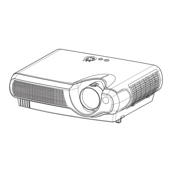
Page 3: Part Names
CP-S235 (C10SM2) 3. Part names Projector Zoom ring Air filter cover (An air filter is Focus ring inside.) Lens (The picture is Remote sensor projected from here.) Elevator button Elevator feet Lens cap Projector (Front/Right) INPUT button POWER indicator TEMP indicator toggles between the signal tells the state of power lights or blinks when any... -
Page 4: Remote Control Transmitter
CP-S235 (C10SM2) (STANDBY/ON) SEARCH button RGB button button searches for an input selects the input signal of prepares for turning the signal between the RGB port. power on/off. following signal ports of AUTO button VIDEO button RGB, VIDEO, S-VIDEO executes automatic toggles between the signal and COMPONENT VIDEO. -
Page 5: Adjustment
CP-S235 (C10SM2) 4. Adjustment 4-1 Before adjusting 4-1-1 Selection of adjustment Table 4-1: Relation between the replaced part and adjustment When any parts in the table 4-1 are changed, choose Adjustment Replaced White Colour the proper adjusting items with the chart. Ghost Flicker NRSH... - Page 6 CP-S235 (C10SM2) 4-3 Flicker adjustment (V.COM adjustment) Signals for internal adjustment Adjustment procedure 1. Make this adjustment after completing the adjustment in 4-2 Ghost adjustment. 2. Use DAC-P - V.COM - R: in the FACTORY MENU to adjust so that the flicker at the centre of the screen is less than the flicker at the periphery.
- Page 7 CP-S235 (C10SM2) 4-6 Colour uniformity adjustment Preparations 1. Perform these adjustments after the white 6. To temporarily turn correction off, place the cursor balance adjustment described in Section 4-5. on [C.UNIF.] in the Adjust Tone menu and press the 2. Make a colour uniformity adjustment for the [ ] key.
- Page 8 CP-S235 (C10SM2) Adjustment procedure 1 (when a colour differential meter is used) 9. Similarly, measure adjustment points [No.3] to 1. First adjust [MID-L] tone [G:]. [No.17] and adjust their colour co-ordinates starting 2. Select adjustment point [No.2][G:]. in order from the small number points. When the background is not [G] monochrome, This completes adjustments required for [MIN].
- Page 9 CP-S235 (C10SM2) Adjustment procedure 2 (visual inspection) 1. First adjust [MIN] tone [G:]. 6. View measurement points [No.2], [No.3], [No.10] 2. Select [No.2] [G:]. and [No.11]. Adjust the [R] and [B] of each If the background is [G] monochrome, press the measurement point so that they have the same [ENTER] key on the Remote control transmitter to color as measurement point [No.1].
- Page 10 CP-S235 (C10SM2) 4-7 AIR-SENSOR adjustment When the MAIN board or the SENSOR board is replaced, perform this adjustment after completing reassembling the projector. 1. Open SERVICE MENU and choose AIR-SENSOR by using button. Service menu comes up by following operation. Set the cursor on the OPTION menu and press the MAGNIFY OFF button on the Remote controller.
-
Page 11: Troubleshooting
CP-S235 (C10SM2) 5. Troubleshooting Check points REMC Board E802 E801 E805 E302 E804 P701 E800 D841 D302 D303 (TEMP) P601 (LAMP) E7A1 D301 (POWER) E301 MAIN Board ESPL ET01 S301 S302 EA01 EV01 (P-ON) (INP) E102 E101 E103 SENSOR Board Rear view ET01 CNCT... - Page 12 CP-S235 (C10SM2) Power cannot be turned on voltage input Disconnect at pins TSW form Power unit Open E800 on the MAIN (circuit). And check board at standby TSW short or mode? open? : +12V : +17V Short : +6.6V : +4.1V Fuse Filter unit Power unit (circuit)
- Page 13 CP-S235 (C10SM2) Lamp does not light What is the Light state of LAMP Is the LAMP Install the Lamp indicator D303 during installation correct? operation? No light Light Change the lamp. Lamp Does lamp light? Not light Is the voltage at the of E804 on the MAIN board MAIN board fixed to "L"...
- Page 14 CP-S235 (C10SM2) Picture is not displayed when the RGB signal is input Check at operating mode voltage input at pins Power unit E800 on the (circuit) MAIN board? : +12V : +17V :+6.6V :+4.1V MAIN board LCD panel Picture is not displayed when the VIDEO, S-VIDEO, Component Signal is input Check at operating mode voltage input at...
- Page 15 CP-S235 (C10SM2) No sound Check at operating mode voltage input at pin Power unit (circuit) of the E800 on the MAIN board? : +12V : +17V : +6.6V : +4.1V Turn off the projector and about 8 disconnect the Speaker MAIN board cable from ESPL.
-
Page 16: Service Notes
CP-S235 (C10SM2) 6. Service notes 6-1 Lead-free solder [CAUTION] This product uses lead-free solder (unleaded) to help preserve the environment. Please read these instructions before attempting any soldering work. CAUTION Always wear safety glasses to prevent fumes or molten solder from getting into the eyes. Lead-free solder can splatter at high temperatures (600˚C). - Page 17 CP-S235 (C10SM2) 6-2 Cautions when removing the MAIN board When removing the MAIN board, there is danger of damaging the connector connecting cables. 1) Disconnect 11 cables and remove 4 screws. ATTENTION Handling FPC cable Be careful not to add strong load, such as pulling or twisting the FPC cable. If load is added to FPC cable, convergence may shift.
- Page 18 You should not separately replace the parts of the liquid crystal LCD/Lens prism because they only work properly when used together. Therefore, you can either replace the LCD/Lens prism assembly or send the whole LCD/Lens prism assembly unit back to HITACHI where we will replace the malfunctioning part, recondition the device and send it back to you.
- Page 19 CP-S235 (C10SM2) 3. Maintenance point Swab E a c h c o l o u r p a r t h a s s a m e Holder construction. Optical filters By using swab and air duster, you can easily remove dust from Panel panel and optical filters.
-
Page 20: Putting Batteries
CP-S235 (C10SM2) 6-5 Putting batteries CAUTION Always handle the batteries with care and use them only as directed. Improper use may result in battery cracking or leakage, which could result in fire, injury and/or pollution of the surrounding environment. • Keep the battery away from children and pets. •... -
Page 21: Air Filter
CP-S235 (C10SM2) 6-6 Air filter The air filter should be cleaned about every 100 hours. If the indicators or a message prompts you to clean the air filter, clean the air filter as soon as possible. If the air filter becomes clogged by dust or the like, internal temperature rises and could cause malfunction. - Page 22 CP-S235 (C10SM2) 6-5 Lamp WARNING HIGH VOLTAGE HIGH TEMPERATURE HIGH PRESSURE The projector uses a high-pressure mercury glass lamp. The lamp can break with a loud bang, or burn out, if jolted or scratched, handled while hot or worn-out over time. Note that each lamp has a different lifetime and some may burst or burn out soon after you start using them.
- Page 23 CP-S235 (C10SM2) Replacing the lamp If the indicators or a message prompts you to replace the lamp, replace the lamp as soon as possible. Using the lamp for long periods of time, or past the replacement date, could cause it to burst. WARNING •...
- Page 24 CP-S235 (C10SM2) 6-8 Notice of AUTO adjustment Use of AUTO adjustment with the image through RGB input optimises V_POSI, H_POSI, H_SIZE and H_PHASE automatically. In case that projected image has dark tone around its peripheral, AUTO operation sometimes makes artifacts in the image, shifts capture area and so on.
- Page 25 PIN BOX (ID Inquiring Code) 2. Send the HITACHI sales company the Inquiring code (10 digits) to receive the correct PIN code. 3. With the PIN BOX menu displayed, input the correct PIN code. Enter the correct PIN CODE that has been received.
-
Page 26: Related Messages
CP-S235 (C10SM2) 6-10 Related messages When the unit's power is ON, messages such as those shown below may be displayed. When any such message is displayed on the screen, please respond as described below. Message Description CHANGE THE LAMP Lamp usage time is approaching 2000 hours. (*2) Preparation of a new lamp and an early lamp change is recommended. -
Page 27: Indicator Lamps
CP-S235 (C10SM2) 6-11 Indicator lamps ATTENTION When the interior portion has become overheated, for safety purposes, the power source may be automatically turned off and the indicator lamps may also be turned off. In such a case, press the "○" (OFF) side of the power switch and wait at least 45 minutes. -
Page 28: Service Menu
CP-S235 (C10SM2) SERVICE MENU To display the OSD for “SERVICE MENU” set up. SERVICE MENU By the control panel By the remote control transmitter C10S 1. Display the menu by the “MENU” 1. Display the menu by the “MENU” FANSPEED B-SPEED button. - Page 29 CP-S235 (C10SM2) Setup of filter time (“ON” or “OFF”) 1. Select the “FILTER TIME” on the OSD using button “ ” . Next press the “ ” to select “FILTER TIME MENU” by the SERVICE MENU. SERVICE MENU C10S FANSPEED B-SPEED SERVICE MENU DURABLE...
-
Page 30: Wiring Diagram
Circuit/ballast power board, Control - Main board wiring Circuit power board wiring Ballast power board wiring (1) Connect TSW. (1) Connect CNBAR. (2) Connect CNPOW and FEB3. (3) Connect FEB2. (4) Connect CN1,CD2,FEB1, and FEB5. Confirm that CN200 is connected properly. CNBAR (confirmation is not possible later) Attach FEB1... - Page 31 Power block wiring (board block SUB ASS'Y) After attaching ballast power block (1) Secure FEB3. Attaching ballast power block (1) Connect and wire CNPWR. (2) Wire lamp lead. (3) Wire CN1 and CD2. CNPOW (4) Wire TSW and CNPOW. Pass CN1 and CD2 through circuit power case fastener. Caution: Parts differ for C10S and C10H.
- Page 32 Guide leads away from optical unit Bottom case assembly wiring positions to prevent leads from After fastening becoming wedged when mounting down the FEBA Arrange speaker and internal air sensor leads optical unit. Bottom case assembly to the Z4 on the as shown below.
- Page 33 Power block integration wiring Guide leads away from duct positions to prevent leads from becoming wedged when mounting ducts. Fasten CNSH, FG, CD2, and crown washer Power block integration to power case with a screw as shown below. Use caution to prevent CN1, (1) Connect CN1.
- Page 34 2. Mounting drive board Duct and drive board mounting wiring (1) Connect CNPOW and #6460 (Underside of board: exercise caution). (2) Connect CNBAR, CNLC, A83, #6800, #6430, CNRM, CNME, #3055, Arrange CNSH lead 1. Mounting duct and CNSH connectors. between main board Screw CNSH as shown below.
-
Page 35: Assembly Diagram
CP-S235 (C10SM2) 8. Disassembly diagram (Notice 3) M: Machine screw T: Tapping screw M3x10 Lamp fan/duct T3x16 T3x12 M3x6(lock) T2x5 Dichroic optics unit LCD/Lens prism (Notice 1) Power supply T3x12 unit T3x12 T3x12 M4x8 T3x12 T3x12 (Notice 5) T3x12 M3x10 (Notice 4) (black) T3x12(black) - Page 36 CP-S235 (C10SM2) M: Machine screw T: Tapping screw Power supply Dichroic optics unit unit LCD/Lens prism M3x8(black) (Notice 2) M3x8 M3x8 M3x6 M3x30 M3x8(black) M3x30 M3x30 MAIN Board Lamp fan/duct M3x6 M3x10 M3x10 T3x35 T3x8 T3x35...
- Page 37 CP-S235 (C10SM2) Notice 1. After attaching MAIN board assembly to case with 4. Align shield case joints. M3x6 lock screws, tighten screws on back of Outside bottom case. 2. To remove power board from shield case, push board in direction of arrow, and unlock catches (a) and (b) on board holders with screwdriver.
-
Page 38: Replacement Parts List
CP-S235 (C10SM2) 9. Replacement Parts list THE UPDATED PARTS LIST FOR THIS MODEL IS AVAILABLE ON ESTA Power cord RGB cable Remote control... -
Page 39: Rs-232C Communication
CP-S235 (C10SM2) 10. RS-232C communication Connecting the cable (1) Turn off the projector and the computer power supplies. (2) Connect the CONTROL port of the projector with a RS-232C port of the computer by a RS-232C cable. Use the cable that fulfills the specification shown in the following figure. (3) Turn on the computer power supply and after the computer has started up, turn on the projector power supply. - Page 40 CP-S235 (C10SM2) Requesting projector status (Get command) (1) Send the request code Header + Command data (‘02H’+‘00H’+ type (2 bytes)+‘00H’+‘00H’) from the computer to the projector. (2) The projector returns the response code ‘1DH’+ data (2 bytes) to the computer. Changing the projector settings (Set command) (1) Send the setting code Header + Command data (‘01H’+‘00H’+ type (2 bytes) + setting code (2 bytes)) from the computer to the projector.
-
Page 41: Command Data Chart
CP-S235 (C10SM2) Command data chart Command data Names Operation type Header Action Type Setting code BE EF 06 00 B9 D3 02 00 07 20 00 00 Keystone Increment BE EF 06 00 DF D3 04 00 07 20 00 00 Decrement BE EF 06 00... - Page 42 CP-S235 (C10SM2) Command data Names Operation type Header Action Type Setting code English BE EF 06 00 F7 D3 01 00 05 30 00 00 FRANÇAIS BE EF 06 00 67 D2 01 00 05 30 01 00 Deutsch BE EF 06 00 97 D2 01 00...
- Page 43 CP-S235 (C10SM2) Command data Names Operation type Header Action Type Setting code BE EF 06 00 EF F6 01 00 B3 30 05 00 BE EF 06 00 7F F7 01 00 B3 30 04 00 BE EF 06 00 4F F5 01 00 B3 30...
- Page 44 CP-S235 (C10SM2) Command data Names Operation type Header Action Type Setting code BE EF 06 00 0D 83 02 00 00 21 00 00 V Position Increment BE EF 06 00 6B 83 04 00 00 21 00 00 Decrement BE EF 06 00 BA 82...
- Page 45 CP-S235 (C10SM2) Command data Names Operation type Header Action Type Setting code BE EF 06 00 26 72 01 00 06 22 01 00 MIDDLE BE EF 06 00 D6 72 01 00 06 22 02 00 Video NR HIGH BE EF 06 00 46 73...
- Page 46 CP-S235 (C10SM2) Command data Names Operation type Header Action Type Setting code BE EF 06 00 31 D3 02 00 01 20 00 00 Volume Increment BE EF 06 00 57 D3 04 00 01 20 00 00 Decrement BE EF 06 00 86 D2 05 00...
-
Page 47: Block Diagram
MAIN PCB Flash EEPROM A/D, PLL RGB in 1st PLL THC7216 COLOUR 0.55" LCD RGB out UNIFORMITY CLAMP SVGA PANEL & with LENZ LEVEL TIMING Component SHIFTER GENERATOR Video PW168-05RK VIDEO CONTROL PCB Image Processor DECODER Video SELECTOR TC90A92AFG 2nd PLL S-Video RS-232C Crystal... -
Page 48: Connector Connection Diagram
CP-S235 (C10SM2) 12. Connector connection diagram 30P FPC(Flat) With Panel(OPT Unit) Y IN SVGA Wide (EPSON) (EPSON) 1:COM 1:NC Pb/Cb IN 2:VVDD 2:DY 3:DWN 3:CLY 4:PCG 4:/CLY Pr/Cr IN 5:VST 5:VDDY 6:VCK 6:LCCOM 7:ENB 7:NC 8:NC 8:NRG VIDEO IN 9:VSS 9:ENB1 10:HCK2 10:ENB2... -
Page 49: Basic Circuit Diagrams
CP-S235 (C10SM2) 13. Basic circuit diagrams Basic circuit diagram list SENSOR Board MAIN Board 3 COVER SWITCH Board MAIN Board 4 REMOTE CONTROL Board MAIN Board 5 MAIN Board 6 FILTER UNIT POWER UNIT CIRCUIT MAIN Board 7 POWER UNIT BALLAST 1 MAIN Board 8 POWER UNIT BALLAST 2 MAIN Board 9... - Page 50 SENSOR BOARD REMOTE CONTROL BOARD COVER SWITCH BOARD PARTS WITH HATCHING ARE NOT MOUNTED SM0541 SENSOR, COVER SWITCH & REMOTE CONTROL BOARDS...
- Page 51 POWER UNIT (CIRCUIT) FILTER UNIT PARTS WITH HATCHING ARE NOT MOUNTED SM0541 POWER UNIT (CIRCUIT) & FILTER UNIT...
- Page 52 VB 8 D117 D115 7 HO IN 2 2 IN HO 7 6 VS COM 3 3 COM VS 6 R129 R125 LO 4 LO 4 ZD100 22 18 PARTS WITH HATCHING ARE NOT MOUNTED SM0541 POWER UNIT (BALLAST) 1...
- Page 53 PARTS WITH HATCHING ARE NOT MOUNTED SM0541 POWER UNIT (BALLAST) 2...
- Page 54 PARTS WITH HATCHING ARE NOT MOUNTED SM0541 CONTROL BOARD...
- Page 55 PARTS WITH HATCHING ARE NOT MOUNTED SM0541 MAIN BOARD 1...
- Page 56 PARTS WITH HATCHING ARE NOT MOUNTED SM0541 MAIN BOARD 2...
- Page 57 PARTS WITH HATCHING ARE NOT MOUNTED SM0541 MAIN BOARD 3...
- Page 58 PARTS WITH HATCHING ARE NOT MOUNTED SM0541 MAIN BOARD 4...
- Page 59 PARTS WITH HATCHING ARE NOT MOUNTED SM0541 MAIN BOARD 5...
- Page 60 PARTS WITH HATCHING ARE NOT MOUNTED SM0541 MAIN BOARD 6...
- Page 61 PARTS WITH HATCHING ARE NOT MOUNTED SM0541 MAIN BOARD 7...
- Page 62 PARTS WITH HATCHING ARE NOT MOUNTED SM0541 MAIN BOARD 8...
- Page 63 PARTS WITH HATCHING ARE NOT MOUNTED SM0541 MAIN BOARD 9...
- Page 64 PARTS WITH HATCHING ARE NOT MOUNTED SM0541 MAIN BOARD 10...
- Page 65 PARTS WITH HATCHING ARE NOT MOUNTED SM0541 MAIN BOARD 11...
- Page 66 Fax: +46 (0) 8 562 711 13 Tel: +39 02 38073415 Servizio Clienti Email: csgswe@hitachi-eu.com Fax: +39 02 48786381/2 Email: customerservice.italy@hitachi-eu.com HITACHI EUROPE S.A.S HITACHI EUROPE LTD (Norway) AB Lyon Office STRANDVEIEN 18 B.P. 45, 69671 BRON CEDEX 1366 Lysaker FRANCE...
Need help?
Do you have a question about the SM0541 and is the answer not in the manual?
Questions and answers