Hitachi CPX380W Service Manual
Multimedia lcd projector
Hide thumbs
Also See for CPX380W:
- User manual (40 pages) ,
- Manuale d'istruzioni (40 pages) ,
- Specifications (2 pages)
Table of Contents
Advertisement
Quick Links
SERVICE MANUAL
Be sure to read this manual before servicing. To assure safety from fi re, electric shock, injury, harmful
radiation and materials, various measures are provided in this Hitachi Multimedia LCD Projector. Be sure to
read cautionary items described in the manual to maintain safety before servicing.
When replacing the lamp, avoid burns to your fi ngers, the lamp becomes very hot.
1. Never touch the lamp bulb with a fi nger or anything else.
2. Never drop it or give it a shock. They may cause bursting of the bulb.
3. This projector is provided with a high voltage circuit for the lamp. Do not touch the electric parts of power
unit (main), when turn on the projector.
4. Do not touch the exhaust fan during operation.
5. The LCD module assembly is likely to be damaged. If replacing the LCD module assembly, do not hold
the FPC of the LCD module assembly.
6. Use the cables which are included with the projector or specifi ed.
1. Features --------------------------------------------------- 2
2. Specifi cations--------------------------------------------- 2
3. Names of each part ------------------------------------- 3
4. Adjustment ------------------------------------------------ 5
5. Troubleshooting ---------------------------------------- 12
6. Service points ------------------------------------------ 17
7. Block diagram ------------------------------------------ 22
SPECIFICATIONS AND PARTS ARE SUBJECT TO CHANGE FOR IMPROVEMENT.
Multimedia LCD Projector
December 2001 Digital Media Systems Division
Caution
ServiceWarning
Contents
8. Connector connection diagram -------------------- 23
9. Wiring diagram ----------------------------------------- 24
10.Basic circuit diagram---------------------------------- 30
11.Disassembly diagram--------------------------------- 48
12.Replacement parts list ------------------------------- 50
13.RS-232C communication ---------------------------- 51
SM0519
CPX380W
PJ750-2
(C4X3)
(C4X3)
Advertisement
Table of Contents

Related Manuals for Hitachi CPX380W


Summary of Contents for Hitachi CPX380W
-
Page 1: Table Of Contents
Be sure to read this manual before servicing. To assure safety from fi re, electric shock, injury, harmful radiation and materials, various measures are provided in this Hitachi Multimedia LCD Projector. Be sure to read cautionary items described in the manual to maintain safety before servicing. -
Page 2: Features
PJ750-2 CP-X380W 1. Features High brightness, High resolution Compact size, light weight for portability RS-232C Communication Complies with VESA DDC1/2B specifications Auto-adjustment function 2. Specifications Drive system TFT active matrix Liquid crystal Panel size 0.9 inches panel Number of pixels 1024 (H) ×... -
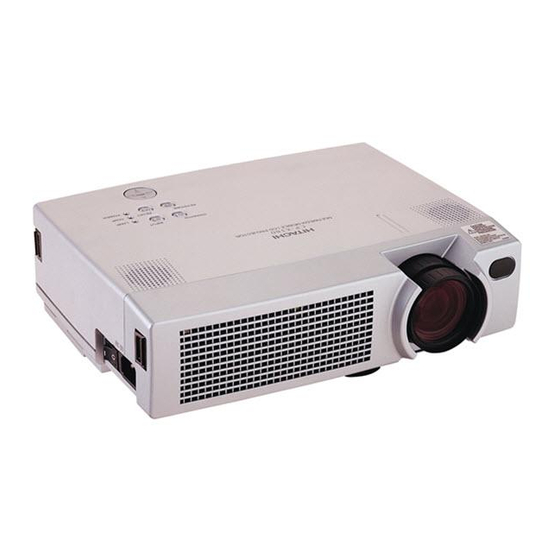
Page 3: Names Of Each Part
PJ750-2 CP-X380W 3. Names of each Part Parts names Speaker Zoom Knob Focus Ring Handle Hook Remote Control Sensor Power Switch Lens AC Inlet (to the Power Cord) Lens Cap Foot Adjuster Ventilation Openings (Intake) FRONT/LEFT VIEW OF THE PROJECTOR Control Panel INPUT Button STANDBY/ON Button... - Page 4 PJ750-2 CP-X380W Remote control transmitter BLANK Button STANDBY/ON Button LASER Button VIDEO Button RGB Button Disk Pad MOUSE / RIGHT Button Used to operate the Used to click the right mouse shift function and mouse button. left click function. KEYSTONE Button AUTO Button RESET Button MENU Button...
-
Page 5: Adjustment
PJ750-2 CP-X380W Model PJ750-2 only 4. Adjustment 4. Set the other [MENU] items as follows. 4-1 Before adjusting a. GAMMA in the IMAGE menu is NORMAL. 1. Before starting adjustment, warm up the projector b. COLOUR TEMP. in the IMAGE menu is NORMAL. for about 10 minutes.(Blank white) c. - Page 6 PJ750-2 CP-X380W 4-4 NRSH adjustment (vertical stripe adjustment) Signals for internal adjustment Adjustment procedure 1. Make this adjustment after completing the adjustment in 4-3 Flicker adjustment. 2. Use DAC-P - NRSH - R: in the Adjustment menu to adjust so that the vertical lines spaced every 6 or /255 /255 /255...
- Page 7 PJ750-2 CP-X380W 11. Adjust Gamma, 0%, G: and R: and B: so that the 16. Adjust Gamma, 43%, R: and B: so that the colour following values. coordinates (x, y) at the centre of the screen take Model PJ750-2 [0%][R:] = -96 on the following values.
- Page 8 PJ750-2 CP-X380W 4-6 Colour uniformity adjustment Preparations 1. Perform these adjustments after the white balance 6. To temporarily turn correction off, place the cursor adjustment described in Section 4-5. on “ON” in the Adjust Tone menu and press the 2. Make a colour uniformity adjustment for the ] key.
- Page 9 PJ750-2 CP-X380W Adjustment procedure 1 (when a colour differential meter is used) 9. Similarly, measure adjustment points [No.3] to 1. First adjust [MID-L] tone [G:]. 2. Select adjustment point [No.2][G:]. [No.17] and adjust their colour coordinates starting When the background is not [G] monochrome, in order from the small number points.
- Page 10 PJ750-2 CP-X380W Adjustment procedure 2 (visual inspection) 1. First adjust [MIN] tone [G:]. 6. View measurement points [No.2], [No.3], [No.10] 2. Select [No.2] [G:]. and [No.11]. Adjust the [R] and [B] of each If the background is [G] monochrome, press the measurement point so that they have the same [MENU SELECT] key on the Remote control colour as measurement point [No.1].
- Page 11 PJ750-2 CP-X380W No. 2 deviation range No. 10 deviation range No. 3 deviation range No. 11 deviation range No. 4 deviation range No. 12 deviation range No. 5 deviation range No. 13 deviation range 3 11 3 11 No. 6 deviation range No.
-
Page 12: Troubleshooting
PJ750-2 CP-X380W 5. Troubleshooting Check points for troubleshooting E805 ESPR DRIVE PCB E302 E801 I256 L818 E808 E800 I812 ESPL E806 S201 I306 P702 P502 E804 S302 S303 E803 D302 E802 P602 I841 D301 D303 E807 S305 S304 I102 CHV33 S307 CHV34 CHV35... - Page 13 PJ750-2 CP-X380W Power cannot be turned on Disconnect Are these TSW from Power Unit Open voltages present on the (Circuit). And check Drive PCB at standby TSW short or mode? open? I812 : +14V IV22 : +17V Short I102 : +6V I841 : +4.3V Fuse...
- Page 14 PJ750-2 CP-X380W Lamp does not light What is the state of Light Light Change the lamp. Lamp LAMP indicator D302 Does lamp light? during operation? No light No light Is the voltage at collector of Q801 on the Drive Drive PCB PCB fixed to "L"...
- Page 15 PJ750-2 CP-X380W Picture is not displayed when the RGB signal is input Check at operating mode Change the Are these signals IS01 on the Signal present at each pin listed on PCB, is it repaired? the Drive PCB? IC (IS01) CH106 : R signal EL4332CS CH102 : G signal...
- Page 16 PJ750-2 CP-X380W No sound Check at operating mode Are these signals present at each pins on the Drive PCB? Signal PCB CHV25 : Audio (L) CHV33 : Audio (R) Drive PCB Speaker Cannot control to RS-232C Check at operating mode Pin No RS-232C SEL0...
-
Page 17: Service Points
PJ750-2 CP-X380W 6. Service points Caution when removing the Upper Case Assembly When you remove the Upper Case Assembly, avoid to damage wires between speakers on the upper case and Drive PCB on the bottom case assembly. Speaker Wire from Speaker Caution when removing the Drive PCB When removing the Drive PCB, there is danger of damaging the connector connecting cables and the Signal PCB. - Page 18 Therefore, regarding these parts, you can either replace the LCD / Lens Prism assembly or send the whole LCD / Lens Prism assembly back to Hitachi, where we will replace the malfunctioning part, recondition the device and send it back to you. Please contact our distributor.
- Page 19 PJ750-2 CP-X380W Loading the Batteries Install the AA batteries into the remote control transmitter. 1. Remove the battery cover. Push the knob while lifting up the battery cover. 2. Loading the batteries. Make sure the plus and minus poles are correctly oriented. 3.
- Page 20 PJ750-2 CP-X380W Replacing the Lamp 1. Switch the projector OFF, remove the power cord from the power outlet, and wait at least 45 minutes for the unit to cool. 2. Prepare a new lamp. 3. Check that the projector has cooled suffi ciently, and gently turn it upside down.
- Page 21 PJ750-2 CP-X380W Message table On-screen display The following messages are displayed on the screen. "CHANGE THE LAMP" "AFTER REPLACING LAMP, RESET Lamp has 1,700 hours on it and may need to be changed. THE LAMP TIMER" "CHANGE THE LAMP" "AFTER REPLACING LAMP, Lamp has 1,979 hours on it.
-
Page 22: Block Diagram
SIGNAL PCB DRIVE PCB EEPROM 1M SRAM Flash ROM A/D, PLL SIGNAL EXT.I/O CXA3506R SELECTOR 1st_PLL RGB 2 CLAMP COLOUR SYNC UNIFORMITY Component & SEPARATOR Video CXA2151Q TIMING PW164-10RK VIDEO 0.9 type LCD GENERATOR S-Video Image_PROCESSOR LEVEL DECODER XGA PANEL Video VPC3230Q SHIFTER... -
Page 23: Connector Connection Diagram
PJ750-2 CP-X380W 8. Connector Connection Diagram E950 S-VIDEO ESM2 EV01 E302 PWB ass'y DRIVE ass'y C.VIDEO MOUSE SENSOR 19 REMOTE E806 L.IN 1 PWB 2 REMOTE 2 ass'y S.CIN P502 3 REMC P602 S.YIN P702 CVBSIN VDDY FAN1S YDDX E801 2 LCD-B (PANEL-B) ENB2... -
Page 24: Wiring Diagram
Check the connection between CNPWR the CN102 and the CN104. (Because it is impossible to check it afterward) Pass this through a notch of the PCB holder. CNBAR Let the CNPOW and TSW cables cross each other (so that the TSW will not approach the primary side power circuit). - Page 25 Check that the black cover of a lamp lead is securely White cover inserted into the connector. on lamp lead If even a trivial portion of the white cover is visible inside in a state where the black cover is not inserted into the connector as shown in the diagram on the right, shift the black cover appropriately and Shift the black...
- Page 26 CNPOW Do not let the TSW cable sag down (so that it will not approach the primary power side). CNTH Pass through the ballast cover guide after clamping the TSW cable as CNBAR shown in the diagram. Lamp lead INP. RC. PCB Keep individual cables away from positions to mount optical units as shown in the diagram so that the cables will not be caught in when optical units are mounted.
- Page 27 Clamp #6260, #6261, CNTH, CNBAR and CNPOW cables using PAS1. Provide extra length on the #6260 cable by making a loop, etc., at the clamp. Difference in level As regards the CNTH cable, provide some extra CNPOW length if there is any as mentioned above (in order to prevent the sagged cable caused by extra length from touching the front bezel and lens).
- Page 28 Procedures Before mounting the Drive PCB, connect the CNBAR and the CNPOW to a connector on the back of the PCB in a state where you hold the Drive PCB with your hands. Connect the other cables in a state where the Drive board is mounted. Thermistor cable Connect this to the Drive board E302.
- Page 29 * Installing the A83 cable on the upper case TAP1 and affixing of the TAP1 are to be performed in accordance with an assembly drawing. Upper case When installing the front bezel, exercise utmost caution not to Pass the A83 cable through the left side of a get the cable caught in.
-
Page 30: Basic Circuit Diagram
PJ750-2 CP-X380W 10. Basic Circuit Diagram Parts with hatching are not mounted. SENSOR PCB (C4X3) REMOTE CONTROL PCB (C4X3) LIMIT SWITCH PCB (C4X3) - Page 31 POWER UNIT (BALLAST) 1 (C4X3)
- Page 32 POWER UNIT (BALLAST) 2 (C4X3)
- Page 33 PJ750-2 CP-X380W POWER UNIT (CIRCUIT) 1 (C4X3)
- Page 34 PJ750-2 CP-X380W POWER UNIT (CIRCUIT) 2 (C4X3)
- Page 35 PJ750-2 CP-X380W SIGNAL PCB 1 (C4X3)
- Page 36 PJ750-2 CP-X380W SIGNAL PCB 2 (C4X3)
- Page 37 PJ750-2 CP-X380W SIGNAL PCB 3 (C4X3)
- Page 38 PJ750-2 CP-X380W DRIVE PCB 1 (C4X3)
- Page 39 PJ750-2 CP-X380W DRIVE PCB 2 (C4X3)
- Page 40 PJ750-2 CP-X380W DRIVE PCB 3 (C4X3)
- Page 41 PJ750-2 CP-X380W DRIVE PCB 4 (C4X3)
- Page 42 PJ750-2 CP-X380W DRIVE PCB 5 (C4X3)
- Page 43 PJ750-2 CP-X380W DRIVE PCB 6 (C4X3)
- Page 44 PJ750-2 CP-X380W DRIVE PCB 7 (C4X3)
- Page 45 PJ750-2 CP-X380W DRIVE PCB 8 (C4X3)
- Page 46 PJ750-2 CP-X380W DRIVE PCB 9 (C4X3)
- Page 47 PJ750-2 CP-X380W DRIVE PCB 10 (C4X3)
-
Page 48: Disassembly Diagram
PJ750-2 CP-X380W 11. Disassembly Diagram M : Meter screw T : Tapping screw T3X12 T3X12 M3X8 M3X65 M3X65 M3X6 M3X6... - Page 49 PJ750-2 CP-X380W M : Meter screw M3X8 T : Tapping screw M3X25 M3X10 T3X12 T3X12 T3X12 T3X12 T3X12 M3X8 M3X8 T3X12 T3X10 M3X8 M3X8 M3X8 T2X5...
-
Page 50: Replacement Parts List
THE UPDATED PARTS LIST FOR THIS MODEL IS AVAILABLE ON ESTA... -
Page 51: Rs-232C Communication
PJ750-2 CP-X380W 13. RS-232C Communication (1) Turn off the projector and computer power supplies and connect with the RS-232C cable. (2) Turn on the computer power supply and, after the computer has started up, turn on the projector power supply. RS-232C jack Projector Computer... - Page 52 PJ750-2 CP-X380W Requesting projector status (Get command) (1) Send the request code Header + Command data (‘02H’+‘00H’+ type (2 bytes) +‘00H’+‘00H’) from the computer to the projector. (2) The projector returns the response code ‘1DH’+ data (2 bytes) to the computer. Changing the projector settings (Set command) (1) Send the setting code Header + Command data (‘01H’+‘00H’+ type (2 bytes) + setting code (2 bytes)) from the computer to the projector.
- Page 53 PJ750-2 CP-X380W Command Data Chart Command data Names Operation type Header Action Type Setting code BE EF 06 00 3B D3 01 00 00 30 00 00 Orange BE EF 06 00 AB D2 01 00 00 30 01 00 Green BE EF 06 00...
- Page 54 PJ750-2 CP-X380W Command Data Chart Command data Names Operation type Header Action Type Setting code BE EF 06 00 7C D2 02 00 07 30 00 00 Magnify Increment BE EF 06 00 1A D2 04 00 07 30 00 00 Decrement BE EF 06 00...
- Page 55 PJ750-2 CP-X380W Command Data Chart Command data Names Operation type Header Action Type Setting code Normal BE EF 06 00 46 D3 01 00 02 20 00 00 Mute Mute BE EF 06 00 D6 D2 01 00 02 20 01 00 BE EF 06 00...
- Page 56 PJ750-2 CP-X380W Command Data Chart Command data Names Operation type Header Action Type Setting code BE EF 06 00 F1 72 02 00 01 22 00 00 Sharpness Increment BE EF 06 00 97 72 04 00 01 22 00 00 Decrement BE EF 06 00...
- Page 57 PJ750-2 CP-X380W Command Data Chart Command data Names Operation type Header Action Type Setting code BE EF 06 00 CB D0 01 00 08 30 01 00 Sync on G BE EF 06 00 5B D1 01 00 08 30 00 00 BE EF 06 00...
- Page 58 PJ750-2 CP-X380W MEMO...
- Page 59 Fax: +46 (0) 8 562 711 13 Email: csgswe@hitachi-eu.com Tel: +39 02 38073415 Servizio Clienti Fax: +39 02 48786381/2 Email: customerservice.italy@hitachi-eu.com HITACHI EUROPE S.A.S HITACHI EUROPE LTD (Norway) AB Lyon Office STRANDVEIEN 18 B.P. 45, 69671 BRON CEDEX 1366 Lysaker FRANCE...
Need help?
Do you have a question about the CPX380W and is the answer not in the manual?
Questions and answers