Table of Contents
Advertisement
Advertisement
Table of Contents

Subscribe to Our Youtube Channel
Related Manuals for a-them mrx 1120/720

Summary of Contents for a-them mrx 1120/720
- Page 1 MRX 1120/720 A/V RECEIVERS AVM 60 A/V PROCESSOR O P E R A T I N G M A N U A L...
- Page 2 I M P O R T A N T S A F E T Y I N S T R U C T I O N S CAUTION RISK OF ELECTRIC SHOCK DO NOT OPEN CAUTION: TO REDUCE THE RISK OF ELECTRIC SHOCK, DO NOT REMOVE COVER (OR BACK). NO USER-SERVICEABLE PARTS INSIDE.
- Page 3 WARNING: To reduce the risk of fire or electric shock, do not expose this apparatus to rain or moisture. Avoid installing this unit where foreign objects may fall onto this unit and/or this unit may be exposed to liquid dripping or splashing. On the top of this unit, do not place: •...
- Page 4 USA CANADA FCC Information (For US customers) RF Exposure Information IMPORTANT NOTICE: DO NOT MODIFY THIS PRODUCT This equipment complies with FCC/IC radiation exposure limits set forth for an uncontrolled environment and meets the FCC This product, when installed as indicated in the instructions contained in this manual, meets FCC requirements. Modification not radio frequency (RF) Exposure Guidelines in Supplement C to OET65 and RSS-102 of the IC radio frequency (RF) Exposure rules.
- Page 5 DO NOT LOCATE IN THE FOLLOWING PLACES: To ensure long-lasting use, do not locate the unit: • Exposed to direct sunlight. Left 0.2 m (8 in) Above 0.2 m Right 0.2 m or more (8 in) or more (8 in) or more •...
- Page 6 NOTES ON ENVIRONMENTAL PROTECTION At the end of its useful life, this product must not be disposed of with regular household waste but must be returned to a collection point for the recycling of electrical and electronic equipment. The symbol on the product, user’s manual and packaging, point this out.
- Page 7 LICENSE INFORMATION FOR THE SOFTWARE USED IN THE UNIT This product contains one or more free or open source software programs originating from third parties. This free and open source software is subject to the terms of the GNU General Public License, GNU Library/Lesser General Public License, or other different and/ or additional copyright licenses, notices, and disclaimers.
-
Page 8: Table Of Contents
T A B L E O F C O N T E N T S INTRODUCTION ANTHEM ROOM CORRECTION Before Making Connections Before Starting In-Use Notices ARC Software Installation Front Panel Microphone Stand Assembly MRX 720 Rear Panel Microphone Positioning MRX 1120 Rear Panel Measurement AVM 60 Rear Panel... -
Page 9: Introduction
I N T R O D U C T I O N 1.1 BEFORE MAKING CONNECTIONS Check that you have received all items listed below and report discrepancies to your dealer as soon as possible. In case the unit needs to be transported in the future, keep the packing materials. -
Page 10: 1.3 Front Panel
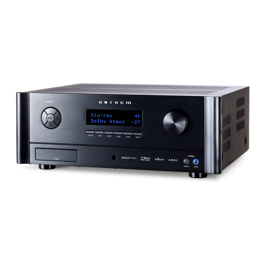
FRONT PANEL (MRX 1120 model shown.) 1 – Navigation buttons 2 – Display 3 – Volume, level functions, and character selection 4 – Power / standby 5 – Input selection 6 – Zone 2 selection 7 – Level selection 8 – Remote control sensor location 9 –... - Page 11 1.4 MRX 720 REAR PANEL US model shown. EU model is similar. MRX 720US 2015.10.26 PRINTING : WHITE FILM NO.:150909-3 1 – FM antenna connection 2 – Wireless antenna connectors 3 – HDMI inputs - HDMI7 supports MHL 4 – HDMI outputs - HDMI1 supports Audio Return Channel 5 –...
-
Page 12: 1.5 Mrx 1120 Rear Panel
1.5 MRX 1120 REAR PANEL MRX 1120US US model shown. EU model is similar. 2015.10.26 PRINTING : WHITE FILM NO.:150907-3 1 – FM antenna connection 2 – Wireless antenna connectors 3 – HDMI inputs - HDMI7 supports MHL 4 – HDMI outputs - HDMI1 supports Audio Return Channel 5 –... - Page 13 1.6 AVM 60 REAR PANEL AVM 60US US model shown. EU model is similar. 2015.10.26 PRINTING : WHITE FILM NO.:150913-3 1 – FM antenna connection 2 – Wireless antenna connectors 3 – HDMI inputs - HDMI7 supports MHL 4 – HDMI outputs - HDMI1 supports Audio Return Channel 5 –...
-
Page 14: 1.7 Remote Control
1.7 REMOTE CONTROL 1 – Main zone power on and standby 2 – Bass, Treble, Balance, Channel Level, Front panel dimmer 3 – Numeric keypad for tuner presets 4 – Input list BASS 5 – Tuner preset 6 – Setup menu TREB LEVEL 7 –... - Page 15 1.8 SPEAKER POSITIONING These illustrations show possible speaker placements. 5.1.2 Configuration 5.1.2 Configuration with one pair in-ceiling height speakers with Dolby enabled front speakers 5.1.4 Configuration 5.1.4 Configuration with two pair in-ceiling height speakers with Dolby enabled front and rear speakers...
- Page 16 7.1.2 Configuration 7.1.2 Configuration with one pair in-ceiling height speakers with Dolby enabled front speakers 7.1.4 Configuration 7.1.4 Configuration with two pair in-ceiling height speakers with Dolby enabled front and rear speakers...
- Page 17 One pair in-ceiling height speakers (side view) Two pair in-ceiling height speakers (side view)
-
Page 18: Connections
C O N N E C T I O N S This section describes connections between system components. Configuration of input and output will be discussed later, in section 3. 2.1 VIDEO INPUT AND OUTPUT With HDMI connection, video and audio are carried together. Connect HDMI output from MRX to a display with HDMI input –... -
Page 19: Audio Connections
2.2 AUDIO CONNECTIONS AUDIO INPUTS AND OUTPUTS Digital audio sources can be connected using an HDMI, coaxial or optical cable. These connections carry linear PCM, Dolby Digital, and DTS audio formats. HDMI connection is generally preferred to ensure that lossless audio is used where sources provide it although MRX 720US optical/coax can also be used for sources outputting 2-channel PCM, Dolby Digital 5.1, and DTS 5.1 without affecting audio quality. - Page 20 LINE OUTPUT AND ZONE 2 OUTPUT Line output is a 2-channel version of the selected input with fixed output level. This can be used with a headphone amp which has its own volume control. Zone 2 has its own volume control and can be used two ways: For independent source selection, connect the source using analog input, or optical/ coaxial input as long as the source is 2-channel PCM.
- Page 21 SPEAKER CONNECTIONS (MRX ONLY) Using speaker wire, connect the positive (+) connection on the speaker to the positive (+) binding post on the appropriate amplifier output, and the negative (–) connection on the speaker to the negative (–) binding post on the same amplifier channel using cable that is insulated to handle the maximum output of the amplifier.
-
Page 22: Antenna
2.3 ANTENNA Connect the FM antenna to the FM ANTENNA connector. Later, when unit is operating move the antenna to find best reception. 2.4 LOCAL AREA NETWORK A network connection is required for configuring Anthem Room Correction, using the Play-Fi App, or using IP control. To use a wired connection, simply connect your router using CAT5 cable. - Page 23 EXAMPLE 1 HDMI IN HDMI IN AVM 60US 2015.10.26 PRINTING : WHITE FILM NO.:150913-3 HDMI OUT HDMI OUT...
-
Page 24: Setup
S E T U P For optimum performance and enjoyment, your AVM/MRX should be properly set up. This may appear like a lot of work but most settings do not need to be changed from defaults. The important ones relate to your display and input connections, and distance from listening area to each speaker. -
Page 25: Speaker Setup
3.1 SPEAKER SETUP If your source components also have bass management and time alignment, be sure to disable them by setting all channels “large” and to the same distance from listener since the AVM/MRX will be performing these tasks. Audio quality will be degraded if these processes are performed twice. - Page 26 FOUR CONFIGURATIONS One speaker configuration is normally suitable but alternate sets of bass management, listening position, level calibration, and ARC equalization values can be entered and stored. This can be useful if your installation varies according to sound-altering characteristics such as screen up vs down, door open vs closed, or with subwoofer vs without.
-
Page 27: Bass Managment
3.2 BASS MANAGEMENT In this menu, information about your speakers is used so that bass does not become distorted. If using Anthem Room Correction, these items will be set during measurement, so you may skip this menu. If your subwoofer has a crossover, it should be bypassed – set its frequency control to the highest frequency. -
Page 28: Listener Position
3.3 LISTENER POSITION Through these settings, sound coming from all speakers is coordinated to reach the listening area at the same time. This way, proper imaging is achieved. The channel with the greatest distance setting will have no delay while channels with shorter distance settings will be delayed accordingly. -
Page 29: Level Calibration
3.4 LEVEL CALIBRATION Level Calibration uses internally generated test noises to match speaker output levels at the listening position. These noises are also a way of checking system connections between receiver, amplifier, and speaker. Audio calibrations from home theater setup discs are not recommended –... - Page 30 CHANNEL LEVEL If you’re calibrating by ear, use the remote control and sit in the listening area. Adjust each channel’s loudness until all levels sound the same. If using an SPL meter, adjust level so it reads 75 dB for each channel. If Noise Level is set while Front-L is at 0 dB, no adjustment of Front-L is needed since the output is the same.
-
Page 31: Input Setup
3.5 INPUT SETUP Inputs and listening mode presets are configured in this section. From the factory, 5 inputs are set but you may change this to anything from 1 to 30 configurations. Input Setup HDMI 1 HDMI 2 HDMI 3 Play-Fi Add Input Zone 2 Input Follows Main... - Page 32 INPUT NAME Using the navigation keys and volume knob each input can be renamed, up to 8 characters long. When finished, press Select. Example – Rename “HDMI 1” to “Blu-ray”: • Highlight “Input Name” and press Select. The first character will be highlighted in red. •...
- Page 33 LISTENING MODE PRESETS A listening mode is processing that enhances source material by increasing the number of output channels. Each mode performs this its own way, providing its own type of sound. To find your preference, spend some time listening to various modes using various sources. To disable presets and make selections entirely on the fly, select “Last Used”.
-
Page 34: Preferences / Line Output
3.6 PREFERENCES / LINE OUTPUT Here you can set preferences as listed. Volumes / REC Output Front Panel Brightness Medium Front Panel Wake-up Up 1 On-Screen Info Display Mute Level Silent Main Max Volume 0 dB Zone 2 Max Volume 0 dB Main Power On Volume -35 dB... - Page 35 HEADPHONE MUTES PRE-OUTS If using external amplification, changing this to No allows the speakers continue to playing while headphones are plugged into the front panel. MUTE LINE OUT OR DIGITAL OUT If using a recording device, select the input that the recorder’s output is connected to. This prevents the recorder’s output from being fed back to its input, which can result in a loud noise.
-
Page 36: Network / Remote Control
3.7 NETWORK / REMOTE CONTROL Network / Remote Control Network Status Device Name AVM 60 Wireless Setup IP Configuration Trigger Configuration TCP Port 14999 Rear IR Front IR Tx Status Control4 ID Tx NETWORK STATUS This displays the AVM/MRX’s IP address once connected to the local area network. DEVICE NAME: This is the name that the AVM/MRX broadcasts, and can be changed using up to 16 characters. - Page 37 PUSH-BUTTON SETUP This method can be used if your router has a WPS (Wi-Fi Protected Setup) button. After making the menu selection, press the button on your router. Push-button mode can also be enabled by holding the Wireless button on the rear panel for 5 seconds (tap again to cancel).
- Page 38 TCP PORT Change this only if there is a conflict with another application that uses 14999. Available settings are 1025 to 49150. REAR AND FRONT IR This allows you to disable each of the AVM/MRX’s infra-red inputs, which can be useful when the AVM/MRX is connected to an IR repeater and is receiving too many signals.
-
Page 39: General Configuration
3.8 GENERAL CONFIGURATION This menu contains power saving, control, and tuner options. General Configuration Auto Off 20 minutes IP Control Standby IP Control Standby HDMI Bypass CEC Control CEC Power Off Control Disabled CEC Power On Control Disabled FM Tuner Steps 100 kHz AUTO OFF When there is no input signal the AVM/MRX will turn off after the selected time: 5, 10, or... - Page 40 When Consumer Electronics Control is enabled it allows controlling one HDMI- connected component using another’s remote control, as long as CEC is also enabled After changing CEC settings or in the other components. Note that when component brands are mixed this control loading factory defaults it may be system may not be reliable.
-
Page 41: Save / Load Settings
3.9 SAVE / LOAD SETTINGS Save / Load Settings Save User Settings Load User Settings Reset on-the-fly Settings Load Factory Defaults SAVE/LOAD USER SETTINGS After selecting Save User Settings and confirming, all menu settings will be stored. If you change settings later and want to recall the saved settings, select Load User Settings and confirm. -
Page 42: System Information
3.10 SYSTEM INFORMATION System Information Update Via USB Release Version 1.0.0 Micro Version 1.0.0 DSP Version 1.0.0 OSD Version 1.0.0 ARC Name ARC Upload Time UPDATE VIA USB AND VERSION NUMBERING: The operational characteristics of the AVM/MRX are controlled by software installed through the USB port on the front panel. -
Page 43: Anthem Room Correction
A N T H E M R O O M C O R R E C T I O N ARC corrects the effects of reflective surfaces and room boundaries on sound quality by measuring the response of each speaker relative to the listening area and equalizing it. -
Page 44: Before Starting
4.1 BEFORE STARTING • Ensure that the AVM/MRX software and ARC-2 software that you will be using are compatible with one another – check www.anthemAV.com for latest versions. • Your ARC microphone and its support file are a system. Before a mic can be used for measurement, its response must be known. -
Page 45: Microphone Stand Assembly
4.3 MICROPHONE STAND ASSEMBLY Screw the telescoping tube into its base and the microphone clip onto the tube. Position the clip vertically. Connect the USB microphone cable to the microphone and slide the microphone into the clip. 4.4 MICROPHONE POSITIONING During measurement the microphone must point straight up. - Page 46 QUICK MEASURE SPEAKER POSITION HELPER If speaker positioning is flexible, particularly for the sub, you can try using Quick Measure before running ARC. Alternatively you can start with a full measurement and then see whether it’s necessary to re-position speakers. To use Quick Measure, select Manual mode instead of Automatic when starting ARC.
-
Page 47: Manual Mode And Targets
4.6 MANUAL MODE AND TARGETS When creating a new file, manual mode is the same as automatic mode except that you must measure, calculate, and upload in separate steps. After the measurement phase, targets can be edited but doing so is recommended only for experienced users. A file created in Automatic mode can be opened in Manual mode to allow target editing. -
Page 48: Advanced Subwoofer Targets
If you did change settings such that a large portion of the bass is being boosted, as would be shown by a wide range of the green corrected curve having higher level than the red measured curve, chances are that your equipment will be stressed more than the sound will improve. -
Page 49: Printing A Report
SUBWOOFER HIGH PASS ORDER Here you may set the low-end slope. If you have a subwoofer that has strong output below 20 Hz, or if it uses its own low-frequency input protection (check with its manufacturer, don’t assume) then selecting Flat may improve system performance. If on the other hand you have a subwoofer that is designed to be flat to a certain frequency then have response that drops very quickly below that, manually selecting a steeper than average slope may be beneficial. -
Page 50: Operation
O P E R A T I O N 5.1 POWER ON / OFF AND VOLUME Main and Zone 2 have separate power controls. During power-on and power-off a mechanical click is produced from the unit – this is normal. Volume comes on according to setup menu setting. -
Page 51: Input Selection
5.3 INPUT SELECTION The number of active inputs varies according to how the Input Setup menu was programmed. To scroll through the next/previous active inputs press the right/left buttons, and to make a selection press SELECT. Front Panel Remote SELECT INPUT Alternatively, press the INPUT button for an on-screen list of inputs. -
Page 52: Dts Play-Fi
PRESETS (remote control only) 30 FM stations can be stored. To store the current station press PRESET then assign a number from 01 to 30. To recall a preset enter the assigned number or press PG/PR up/down for the next/ previous one. -
Page 53: Bass / Treble / Balance
5.7 BASS / TREBLE / BALANCE To change tone, press Bass or Treble on the remote control then up/down. Note that Bass does not affect the subwoofer output – this is handled by the Level adjustment. BASS TREB To change balance press BAL on the remote then up to move the image to the right, or down to move the image to the left. -
Page 54: Dolby Volume And Dynamic Range Control
5.10 DOLBY VOLUME AND DYNAMIC RANGE CONTROL Refer to the Input Setup section for a description of Dolby Volume. Output is forced to a maximum of 7.1 channels if height channels are configured. To change on/off status press DYN on the remote control then up/down. To change Leveler amount press DYN a second time when Dolby Volume is on then adjust. -
Page 55: Limited Warranty
L I M I T E D W A R R A N T Y CANADA & USA The warranty period on new Anthem products is: 5 years: Separate power amplifiers and integrated amplifiers 3 years: Audio/Video preamplifiers and receivers Please register your product at www.anthemAV.com The warranty period begins on the date of purchase from Anthem or an Authorized Anthem Dealer. - Page 56 T H E B I G P I C T U R E M R X 7 2 0 F R O N T P A N E L...
- Page 57 T H E B I G P I C T U R E M R X 7 2 0 R E A R P A N E L...
- Page 58 T H E B I G P I C T U R E M R X 1 1 2 0 F R O N T P A N E L...
- Page 59 T H E B I G P I C T U R E M R X 1 1 2 0 R E A R P A N E L...
- Page 60 T H E B I G P I C T U R E AV M 6 0 F R O N T P A N E L...
- Page 61 T H E B I G P I C T U R E AV M 6 0 R E A R P A N E L...
- Page 62 N O T E S...
- Page 63 N O T E S...
- Page 64 N O T E S...
- Page 65 N O T E S...
- Page 66 DESIGNED IN NORTH AMERICA +1 905-564-1994 8:30 am - 5:00 pm M-F (ET) www.anthemAV.com 2080000327 2015-11-30...
Need help?
Do you have a question about the mrx 1120/720 and is the answer not in the manual?
Questions and answers
how to use spade plug on anthem 1120 amp
The context does not mention the use of spade plugs on the Anthem MRX 1120 amplifier. Therefore, it cannot be determined how to use a spade plug with this amplifier.
This answer is automatically generated