Table of Contents
Advertisement
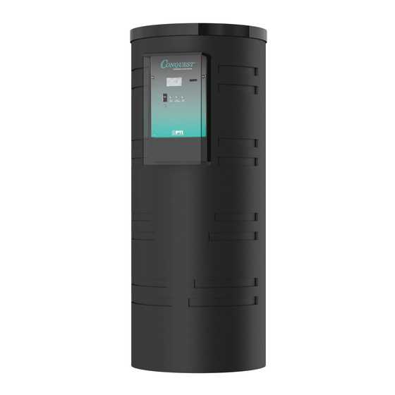
INSTALLATION & MAINTENANCE MANUAL
®
CONQUEST
WATER HEATER with
EOS (ELECTRONIC OPERATING SYSTEM)
MODELS (50, 60, 70, 80) L 130 A-GCML
MODEL (40) L 130 A-GC
Installation and service must be performed by a qualified service installer, service agency or the gas supplier.
IMPORTANT:
THIS
MANUAL
CONTAINS
INFORMATION
REQUIRED
FOR
INSTALLATION,
OPERATION
AND
MAINTENANCE OF THIS EQUIPMENT. READ AND FOLLOW THE INFORMATION IN THIS MANUAL AND ALL OTHER
PROVIDED INSTRUCTIONS, LABELS AND MARKINGS BEFORE INSTALLING, OPERATING OR SERVICING THIS UNIT.
TO THE INSTALLER: After installation, these instructions must be given to the equipment user or left near the appliance.
SPECIAL INSTRUCTIONS TO THE OWNER: Retain this manual for future reference. These instructions contain
important information that will help you in maintaining and operating this appliance.
PVI INDUSTRIES, LLC - Fort Worth, Texas 76111 - Web
www.pvi.com
- Phone 1-800-433-5654
PV500-71 02/16
Advertisement
Table of Contents

Related Manuals for PVI conquest 50 L 130 A-GCML


Summary of Contents for PVI conquest 50 L 130 A-GCML
- Page 1 SPECIAL INSTRUCTIONS TO THE OWNER: Retain this manual for future reference. These instructions contain important information that will help you in maintaining and operating this appliance. PVI INDUSTRIES, LLC - Fort Worth, Texas 76111 - Web www.pvi.com - Phone 1-800-433-5654...
-
Page 2: Table Of Contents
® CONQUEST WATER HEATER TABLE OF CONTENTS Safety Considerations Product Description Water Heater Installation Checking Equipment Before You Install Codes Electrical Requirements Handling and Locating the Water Heater Clearances to Combustible Surfaces Service Clearances Other Codes and Regulatory Clearances and Requirements General Piping Guidelines Inlet and Outlet Connections Building Return Piping... - Page 3 ® CONQUEST WATER HEATER EOS (Electronic Operating System) 10.1 Touch Screen User Interface 10.2 Status Field Display 10.3 Operational Sequence Field Display 10.4 View Menu (Home Screen - Default Display) 10.5 Control System Menus 10.6 Changing the Operating Set Point 10.7 Setting the Real Time Clock 10.8 Scheduled Setback 10.9 Using the Manual Override Menu...
-
Page 4: Safety Considerations
® CONQUEST WATER HEATER SAFETY CONSIDERATIONS IMPORTANT SAFETY NOTE It takes only 5 seconds of skin contact with 140°F water to cause a second degree burn! You must protect against high water temperatures at all lavatories, tubs, showers and other points of hot water contact. Accidental scalding from high water temperatures is a greater risk in some types of installations. - Page 5 ® CONQUEST WATER HEATER WARNING: If the information in the supplied manual(s) is not followed exactly, a fire, explosion or exposure to hazardous materials may result, causing property damage, personal injury or death. AVERTISSEMENT. Assurez-vous de bien suivre les instructions données dans cette notice pour réduire au minimum le risque d’incendie ou d’explosion ou pour éviter tout dommage matérial, toute blessure ou la mort FOR YOUR SAFETY •...
- Page 6 ® CONQUEST WATER HEATER PRODUCT SAFETY INFORMATION REFRACTORY CERAMIC FIBER PRODUCT WITH CRYSTALLINE SILICA WARNING: This product contains or may come to contain crystalline silica, which has been identified by the International Agency for Research on Cancer (IARC) as carcinogenic to humans. This product also contains refractory ceramic fibers, which have been identified by the IARC as possibly carcinogenic to humans.
-
Page 7: Product Description
® CONQUEST WATER HEATER PRODUCT DESCRIPTION Component, Controls and Connection Locations (Locations May Vary) PV500-71 02/16... -
Page 8: Water Heater Installation
® CONQUEST WATER HEATER WATER HEATER INSTALLATION 3.1 Checking Equipment Before You Install • Inspect the unit completely upon receipt from the freight carrier before signing the bill of lading. Inspect the appliance and all accompanying parts for signs of impact or mishandling. Verify the total number of pieces shown on packing slips with those actually received. -
Page 9: Clearances To Combustible Surfaces
® CONQUEST WATER HEATER 3.5 Clearances To Combustible Surfaces The minimum clearance to combustible material is 15" from the top, 24" from the front and zero clearance (0") from the sides and back of the water heater. The Conquest can be installed directly on a combustible floor. Distance minimale aux matériaux combustibles est égale à... -
Page 10: General Piping Guidelines
® CONQUEST WATER HEATER GENERAL PIPING GUIDELINES 4.1 Inlet and Outlet Connections 1. Use only non-ferrous water piping and fittings. Do not use galvanized pipe or fittings. Use of ferrous or galvanized pipe or fittings can cause rust to form. 2. - Page 11 ® CONQUEST WATER HEATER SINGLE STORAGE WATER HEATER WITH SUPPLEMENTAL STORAGE TANK TWO WATER HEATERS WITH REVERSE RETURN PIPING PV500-71 02/16...
-
Page 12: Requirement For 180°F Delivered Water To A Dish Machine
4. The dish washer application must include a 15 gpm circulation loop between the booster heater and the dish machine. A B&G NBF 22 pump with a minimum 1-inch pipe return to the heater is recommended and is available from PVI. 5. All dishwashing machines meeting National Sanitation Foundation (NSF) requirements must operate between 15 and 25 PSI water flow pressure. -
Page 13: Booster Heater Applications
6. The booster heater application must include a 10 gpm circulation loop between the booster heater and the dish machine. A B&G NBF 22 pump with a minimum 1-inch pipe return to the heater is recommended and is available from PVI. 7. All dishwashing machines meeting National Sanitation Foundation (NSF) requirements must operate between 15 and 25 PSI water flow pressure. - Page 14 Connect a condensate drain line or the PVI Condensate Neutralization System to the barbed hose connection, sized for 1/2" ID heavy wall Vinyl tubing rated for 170ºF or higher, located at the end of the condensate trap. All piping from the condensate trap to the suitable drain must remain below the highest point (top of the condensate outlet pipe) on the properly attached condensate trap.
-
Page 15: Condensate Neutralization System (Optional
The condensate neutralizer reduces or avoids the need for separate chemical treatment or dilution using substantial quantities of tap water. Contact your local PVI representative to obtain a Condensate Neutralization System and follow the instructions included for assembly and connection. -
Page 16: Gas Supply And Piping
® CONQUEST WATER HEATER Condensate Trap with Optional Condensate Neutralizer Located Below Conquest GAS SUPPLY AND PIPING Verify the type of gas specified on rating plate is supplied to the unit. This unit is orificed for operation up to 2000 feet altitude. -
Page 17: Gas Piping Size
® CONQUEST WATER HEATER 6.5 Gas Piping Size Do not use the gas pipe connection size to determine the gas supply piping. Designing and sizing a gas supply piping system requires consideration of many factors and must be done by a gas supply piping expert. Always follow NFPA 54 National Fuel Gas Code for gas pipe sizing and gas pipe system design. -
Page 18: Combustion And Ventilation Air
® CONQUEST WATER HEATER 6.7 Gas Connection 1. Safe operation of unit requires adequate gas supply with the required static and dynamic (flow) pressures. Actual piping selection depends on many variables that must be carefully considered by the gas piping system designer. 2. -
Page 19: Maximum Allowed Remote Combustion Air Inlet Length
® CONQUEST WATER HEATER NOTE: This unit may be installed with a remote air intake system which uses a make-up air duct to draw combustion air directly from outdoors. WARNING: Adequate clean combustion air must be provided to the appliance. The appliance must never operate under a negative pressure. -
Page 20: Remote Combustion Air Cap
Before operation of a combined remote air ducting system, all of the duct design firm’s system installation and operation requirements must be in place, their instructions followed and the system must be properly maintained. -
Page 21: Optional Filter Box For Dusty Or Dirty Combustion Air
® CONQUEST WATER HEATER 7.6 Optional Filter Box for Dusty or Dirty Combustion Air The field installed optional air inlet filter box must be attached to the combustion air inlet on any appliance located where it is exposed to dusty, dirty or lint filled combustion air. Replace the filter on a 3 to 6 month schedule, or more often, based on severity of contamination Inadequate combustion air or non-combustible particulate matter such as dust, dirt, dryer lint, concrete dust, dry wall dust or the like can be drawn in with combustion air and block burner ports. -
Page 22: Venting
® CONQUEST WATER HEATER VENTING 8.1 Venting the CONQUEST: All Conquest models use the positive pressure generated by the burner system blower to push combustion products out of the vent. Since the vent system is under positive pressure and must be capable of containing condensate, it must be constructed of schedule 40 solid PVC or CPVC pipe. - Page 23 ® CONQUEST WATER HEATER Testing for leaks – Once the vent system is installed, it must be checked to confirm all joints in the vent system are air and water tight. After the vent is assembled, close the end of the vent with a taped plastic bag or some other temporary closure.
-
Page 24: Vertical Or Horizontal Vent Termination
® CONQUEST WATER HEATER The following vent information is provided for use in design calculations, if needed: Venting Specifications Combustion Air Max Vent Input MBtu/h Volume (cfm) Press. " W.C. 8.3 Vertical or Horizontal Vent Termination: 1. The vent terminal must have a minimum clearance of 4 feet (1.22 m) horizontally from, and in no case be located above or below, unless a 4 foot (1.22 m) horizontal distance is maintained from electric meters, gas meters, regulators and relief equipment. -
Page 25: Optional Concentric Vent For Combustion Air And Exhausting Flue Products
ULC S636 and comply with the non-metallic vent listing requirements in CAN/CSA B149.1-10 Natural Gas and Propane Installation Code. The following IPEX System 636 Concentric Vent Termination Kits are available through PVI for Conquest water heaters: PVI Part No. - Page 26 ® CONQUEST WATER HEATER The following information describes the components and installation methods for the IPEX System 636 Concentric Vent Termination Kit: ITEM NO. DESCRIPTON Wye-(Concentric) Rain Cap Exhaust Vent Pipe (Inner) Fresh Air Intake Pipe (Outer) Stainless Steel Screw & Nut Notes: •...
- Page 27 ® CONQUEST WATER HEATER Concentric Vent Kit Assembly, Installation and Support 1. Follow the concentric vent kit instructions to properly assemble the kit. 2. Follow the concentric vent kit instructions to locate and cut a hole in the roof or wall large enough to accommodate the largest dimension of the kit.
-
Page 28: Connecting To An Existing Vent System
® CONQUEST WATER HEATER Mechanically Fastened Rain Cap The Rain Cap must be installed with the supplied Stainless Steel screw and lock nut, and in accordance with instructions and diagram below. 1. Locate the drill location dimple on the outside of the rain cap. 2. -
Page 29: Cathodic Protection
9.2 Cathodic Protection PVI water heaters do not utilize cathodic protection. However, in hot water systems utilizing cathodic protection, hydrogen gas can be produced when the hot water system has not been used for a long period of time (generally two weeks or more). - Page 30 ® CONQUEST WATER HEATER THE ELECTRONIC OPERATING SYSTEM (EOS) The Conquest EOS consists of three components: The Platform Ignition Module (PIM), plug-in ID card and the Control Display. The PIM is connected to the control display using an RJ485 patch cable. All communication between the PIM and control display as well as the power to the control display is through this cable.
- Page 31 ® CONQUEST WATER HEATER 10.2 Status Field Display The Status Field displays the current operating status of the control display. Most items in the status field are only visible when in the View Menu or an alarm condition is present. Item Description Sanitation Mode is active.
- Page 32 ® CONQUEST WATER HEATER 10.4 View Menu (Home Screen - Default Display) Menu Icon The CTRL TEMP is the operating temperature sensed at the top of the tank Home Button. Return to the ‘Home’ Screen from any menu. Press and hold for 3 Home seconds to access the Button...
- Page 33 ® CONQUEST WATER HEATER 10.5 Control System Menus The control display has multiple access levels. System critical settings will not be available for adjustment. The settings which can be adjusted by the user will display UP and DOWN adjustment arrows on the right side of the display screen.
- Page 34 ® CONQUEST WATER HEATER 10.7 Setting The Real Time Clock (User & Installer Level Access) The TIME MENU allows the user to program the time of day, the date and the year. A 12 or 24 hour time clock as well as daylight saving time can be selected.
- Page 35 ® CONQUEST WATER HEATER • At 4:00pm the 2 occupied period will begin and the occupied set point will be used until the 2 unoccupied period begins at 10:00pm. • From 10pm until 6:00am, the unoccupied set point will then be used. Notice that schedule times and set points are identified as occupied (Occ) or unoccupied (UnOcc) here.
- Page 36 ® CONQUEST WATER HEATER 10. The next screen is SAN PUMP. To force on the SANI pump, turn this setting to ON. 11. The next screen is HTR PUMP. To force on the integral tank circulator, turn this setting to ON. 12.
- Page 37 ® CONQUEST WATER HEATER COMMUNICATIONS AND DIAGNOSTICS 11.1 Indicators The PIM has three LED indicators to display operational status and to help diagnose system error conditions: • Power: Green LED indicating the PIM module is receiving 24 VAC power. • Alarm/Test: Amber LED which indicates the PIM is in Commission Test Mode or that a diagnostic alarm (fault) is present.
- Page 38 ® CONQUEST WATER HEATER condition may be caused by a sensor failure or a faulty control board. Indicates a problem with the top temperature sensor, possibly a broken or HTR TOP shorted sensor wire or failed sensor. NOTE: The top sensor and the high limit sensor or located in the same probe body.
- Page 39 ® CONQUEST WATER HEATER 11.8 ID Card The PIM determines its operating parameters by reading the identification code of an external plug-in ID card. The ID card is connected to the PIM at the J6 connector. NOTE: This ID card must be present for the PIM and appliance to operate. This card selects the proper settings in the PIM's memory for various appliance models.
- Page 40 ® CONQUEST WATER HEATER 12.1 EOS Register List Read/ Register Parameter Type Format Units Range Write Address 0=IDLE, 1=PREPurge, 2=IGNition, 3=BURNer Heater Ignition Read Input Enum on, 4=postPURG, 5=FAIL Upper Tank Temperature Read Input °F -22 to 266 Lower Tank Temperature Read Input °F...
- Page 41 ® CONQUEST WATER HEATER 12.2 Error Codes Code Description No Error Control Display Errors EEPROM Outdoor Sensor Supply Sensor DHW Sensor Vent Limiting FTBus Communication PIM Errors LWCO Remote Proof Air Pressure Low Gas Pressure Boiler Outlet/Tank Top Sensor Boiler Inlet/Tank Bottom Sensor Vent Sensor Hi-Limit Sensor Ignition Failure...
- Page 42 ® CONQUEST WATER HEATER REMOTE CONNECTIONS – TERMINAL STRIP 13.1 Making BMS/BAS remote connections for analog and binary (on/off) signals A terminal strip for the remote connection is located behind the bottom control panel door and is accessed removing the two thumb screws a lifting the hinged door. IMPORTANT: Do not use single strand bell wire for remote field connections to terminals R1-R2 and C1-C2.
- Page 43 ® CONQUEST WATER HEATER SEQUENCE OF OPERATION 1. Incoming 120VAC a. Full time power to the Fuse b. Full time power to the Main Control Switch 2. Power On - When the main control switch is turned on: a. 120V is applied to the step-down transformer (24V) b.
- Page 44 ® CONQUEST WATER HEATER 6. Ignition - When dwell time is completed a 4-second Trial for Ignition (TFI) period is initiated: a. The Gas Safety Valves are energized. b. The hot surface element is de-energized during the last second of the TFI period. c.
- Page 45 • Product Installation & Maintenance Manuals • Start-up Report with instructions • Local, State, & Federal Codes • Website: www.pvi.com • Technical Support: 1-800-433-5654 15.4 On Site Considerations • Electrical Supply in accordance with the Nameplate Rating • Adequate uncontaminated indoor or outdoor combustion air •...
- Page 46 ® CONQUEST WATER HEATER • Check the back of the digital control display board on the hinged panel to see if a 2-wire, RS-485 communication cable is connected. These wires must be removed to isolate the water heater from the Building Automation System during startup.
- Page 47 ® CONQUEST WATER HEATER CONFIRM THE SUPPLY GAS PRESSURE WARNING: If you smell gas: Do not try to light any appliance. Do not try to touch any electrical switch or use a phone in your building. Immediately call your gas supplier and follow their instructions. For Natural Gas, the maximum inlet static gas pressure must not exceed 14.0 inches water column and must not drop below 3.5 inches water column during operation.
- Page 48 4. Burner Combustion Adjustment WARNING: If at any point carbon monoxide is in excess of 200 ppm, contact PVI Customer Care for assistance. WARNING: Do not continue to operate the appliance with carbon monoxide levels above 200 ppm.
- Page 49 ® CONQUEST WATER HEATER NOTE: Do not attempt to adjust combustion based on manifold pressure alone. Manifold pressure should only be used as a reference point. It should not be necessary to adjust the regulator for this model. See Gas Train Illustrations for details.
- Page 50 ® CONQUEST WATER HEATER 5. Check The Vent Pressure With the combustion properly adjusted, now use the test hole in the flue vent to measure the vent pressure. With the burner firing, confirm the vent pressure does not exceed .5” W.C. Pressure in excess of .5” W.C. indicates a venting sizing issue that must be addressed by the installer before operating the water heater.
- Page 51 Tight construction of the properly installed and assembled heater enclosure does not provide a haven for pests. If the floor bolting access covers do not seal completely, they must be replace with direct replacement covers, available from PVI. TROUBLESHOOTING PROCEDURE Before troubleshooting the system, check the following items: •...
- Page 52 ® CONQUEST WATER HEATER 18.1 General Troubleshooting Symptom Probable Cause Corrective Action Power Supply Check fuse and/or circuit breaker. Check if On-Off switch is illuminated when on. If not check panel On-Off Switch fuse or incoming power. Temperature Control Check that the operating temperature control is set higher than the temperature of the water heater.
- Page 53 ® CONQUEST WATER HEATER 18.2 LED Error Code Listing The following table lists the errors detected by the Platform Ignition Module (PIM) control and the associated LED indications. Error Mode LED Code Recommended Troubleshooting Normal Operation Red LED Steady ON, Check that the proper ID card is securely connected.
- Page 54 ® CONQUEST WATER HEATER REPLACEMENT PARTS 19.1 Blower & Burner Assembly (Optional components may not be shown) Models (40, 50, 60, 70, 80) L 130A-GC(M)L ITEM DESCRIPTION 40 L 50 L 60 L 70 L 80 L ADAPTER,FLEXIBLE RUBBER 4 X 3 119469 119469 119469...
- Page 55 ® CONQUEST WATER HEATER 19.2 Control Panel Components ITEM DESCRIPTION 40 L 130A-GCL 50-80 L 130A-GCML Digital Control Display HMI TEKMAR 126070 126070 SWITCH, SPST N.C. MOMENTARY CONTACT SELECTA #SS229 70573 70573 SWITCH, SPST N.O. MOMENTARY CONTACT SELECTA #SS228 75908 75908 FACE PLATE DECAL 126335...
- Page 56 ® CONQUEST WATER HEATER 19.3 Drain Valve – T & P Relief Valve – Integral Circulating Pump Assembly ITEM DESCRIPTION 40 L 130A-GCL 50-80 L 130A-GCML FLANGE, MTG BRONZE INTEGRAL PUMP PL 119301 119301 MOTOR, PUMP B & G #1BL113 MODEL #PL-75 115 VAC W/IMPELLER 120090 120090 O-RING, GASKET 4.25 OD X 3.50 ID X .375...
- Page 57 ® CONQUEST WATER HEATER 19.5 Component Wiring and Routing Details PV500-71 02/16...
- Page 58 4, 5 & 6 below. 4. All gaskets on disassembled components must be replaced on reassembly with exact, Factory Authorized, ® replacement parts only. Gasket kits are available from your PVI Industries Representative or by contacting PVI ®...
- Page 59 11. All replacement parts are available through your PVI Industries Dealer. If you need assistance identifying or contacting your local dealer, you may contact PVI Industries, LLC directly at the address and telephone number located on the first and last page of this manual.
- Page 60 ® CONQUEST WATER HEATER RECOMMENDED MAINTENANCE SCHEDULE Regular service by a qualified service agency and routine maintenance must be performed to ensure safe, reliable and efficient operation. Yearly (Every 12 Months) Schedule annual service call by qualified service agency. 1. Check for piping leaks around pumps, relief valves, and tank connections. Repair, if found. 2.
- Page 61 ® CONQUEST WATER HEATER REQUIREMENTS FOR THE COMMONWEALTH OF MASSACHUSETTS: This equipment complies with Massachusetts State Fuel Gas and Plumbing Codes CMR 248 3.00-10.00 as amended. For all side wall horizontally vented gas fueled equipment installed in every dwelling, building or structure used in whole or in part for residential purposes, including those owned or operated by the Commonwealth and where the side wall exhaust vent termination is less than seven (7) feet above finished grade in the area of the venting, including but not limited to decks and porches, the following requirements shall be satisfied:...
- Page 62 ® CONQUEST WATER HEATER Since PVI cannot control the use of the appliance, water conditions, or maintenance, the warranty on the heat exchanger does not cover poor performance, structural failure, or leaking due to an excessive accumulation of scale. Warranty Forms Ship Separately With Each Product...
Need help?
Do you have a question about the conquest 50 L 130 A-GCML and is the answer not in the manual?
Questions and answers