Table of Contents
Advertisement
®
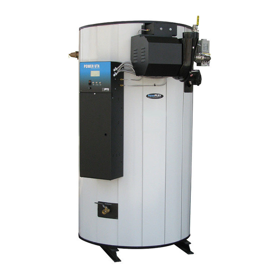
POWER VTX
Water Heater with
EOS (ELECTRONIC OPERATING SYSTEM)
MODELS (50, 75, 100) L 225 A-PVX
Installation and service must be performed by a qualified service installer, service agency or the gas supplier.
IMPORTANT: THIS MANUAL CONTAINS INFORMATION REQUIRED FOR INSTALLATION, OPERATION AND
MAINTENANCE OF THIS EQUIPMENT. READ AND FOLLOW THE INFORMATION IN THIS MANUAL AND ALL OTHER
PROVIDED INSTRUCTIONS, LABELS AND MARKINGS BEFORE INSTALLING, OPERATING OR SERVICING THIS UNIT.
TO THE INSTALLER: After installation, these instructions must be given to the equipment user or left near the appliance.
SPECIAL INSTRUCTIONS TO THE OWNER: Retain this manual for future reference. These instructions contain
important information that will help you in maintaining and operating this appliance.
PVI INDUSTRIES, LLC - Fort Worth, Texas 76111 - Web
www.pvi.com
- Phone 1-800-433-5654
PV500-68 06/16
Advertisement
Table of Contents
Troubleshooting

Subscribe to Our Youtube Channel
Related Manuals for PVI Power VTX 50 L 225 A-PVX


Summary of Contents for PVI Power VTX 50 L 225 A-PVX
- Page 1 SPECIAL INSTRUCTIONS TO THE OWNER: Retain this manual for future reference. These instructions contain important information that will help you in maintaining and operating this appliance. PVI INDUSTRIES, LLC - Fort Worth, Texas 76111 - Web www.pvi.com - Phone 1-800-433-5654...
-
Page 2: Table Of Contents
® POWER VTX WATER HEATER TABLE OF CONTENTS Safety Considerations Product Description Water Heater Installation Checking Equipment Before You Install Codes Electrical Requirements Handling and Locating the Water Heater Clearances to Combustible Surfaces Service Clearances Other Codes and Regulatory Clearances and Requirements General Piping Guidelines Inlet and Outlet Connections Building Return Piping... - Page 3 ® POWER VTX WATER HEATER EOS (Electronic Operating System) 10.1 Touch Screen User Interface 10.2 Status Field Display 10.3 Operational Sequence Field Display 10.4 View Menu (Home Screen - Default Display) 10.5 Control System Menus 10.6 Changing the Operating Set Point 10.7 Setting the Real Time Clock 10.8 Scheduled Setback 10.9 Using the Manual Override Menu...
-
Page 4: Safety Considerations
® POWER VTX WATER HEATER SAFETY CONSIDERATIONS WARNING: If the information in the supplied manual(s) is not followed exactly, a fire, explosion or exposure to hazardous materials may result, causing property damage, personal injury or death. AVERTISSEMENT. Assurez-vous de bien suivre les instructions données dans cette notice pour réduire au minimum le risque d’incendie ou d’explosion ou pour éviter tout dommage matérial, toute blessure ou la mort FOR YOUR SAFETY •... - Page 5 ® POWER VTX WATER HEATER PRODUCT SAFETY INFORMATION REFRACTORY CERAMIC FIBER PRODUCT WITH CRYSTALLINE SILICA WARNING: This product contains or may come to contain crystalline silica, which has been identified by the International Agency for Research on Cancer (IARC) as carcinogenic to humans. This product also contains refractory ceramic fibers, which have been identified by the IARC as possibly carcinogenic to humans.
- Page 6 ® POWER VTX WATER HEATER IMPORTANT SAFETY NOTE It takes only 5 seconds of skin contact with 140°F water to cause a second degree burn! You must protect against high water temperatures at all lavatories, tubs, showers and other points of hot water contact. Accidental scalding from high water temperatures is a greater risk in some types of installations.
-
Page 7: Product Description
® POWER VTX WATER HEATER PRODUCT DESCRIPTION Component, Controls and Connection Locations (Locations May Vary) PV500-68 06/16... -
Page 8: Water Heater Installation
® POWER VTX WATER HEATER WATER HEATER INSTALLATION 3.1 Checking Equipment Before You Install • Inspect the unit completely upon receipt from the freight carrier before signing the bill of lading. Inspect the appliance and all accompanying parts for signs of impact or mishandling. Verify the total number of pieces shown on packing slips with those actually received. -
Page 9: Clearances To Combustible Surfaces
® POWER VTX WATER HEATER 3.5 Clearances To Combustible Surfaces The minimum clearance to combustible material is 16” from the top, 24” from the front and zero clearance (4”) from ® the sides and back of the water heater. The POWER VTX can be installed directly on a combustible floor. - Page 10 ® POWER VTX WATER HEATER SINGLE WATER PIPING SINGLE STORAGE WATER HEATER WITH SUPPLEMENTAL STORAGE TANK PV500-68 06/16...
- Page 11 ® POWER VTX WATER HEATER TWO WATER HEATERS WITH REVERSE RETURN PIPING PV500-68 06/16...
-
Page 12: Condensate Drain, Trap & Disposal
CPVC union. Hand-tighten the CPVC union to seat the internal gasket. Connect a 1/2" ID heavy wall Vinyl tubing rated for 170ºF or higher condensate drain line, or a PVI Condensate Neutralization System to the barbed hose connection located at the end of the condensate trap. Alternatively, 3/4”... -
Page 13: Condensate Neutralization System (Optional
The condensate neutralizer reduces or avoids the need for separate chemical treatment or dilution using substantial quantities of tap water. Contact your local PVI representative to obtain a Condensate Neutralization System and follow the instructions included for assembly and connection. -
Page 14: Gas Supply And Piping
® POWER VTX WATER HEATER GAS SUPPLY AND PIPING Verify the type of gas specified on rating plate is supplied to the unit. This unit is orificed for operation up to 2000 feet altitude. Appliance Btu/h input derates 4% per 1000 feet elevation above sea level. Consult Factory for installations above 2000 feet elevation. -
Page 15: Appliance Isolation During Gas Supply Piping Pressure Test
® POWER VTX WATER HEATER Use the following table to determine the possible pipe size based on distance from gas meter for a Single Unit Installation using Schedule Metallic Gas Pipe.* SINGLE UNIT INSTALLATION SUGGESTED PIPE SIZE Maximum Capacity for Natural Gas* Equivalent Feet MBTU/HR Based on 0.5"... -
Page 16: Combustion And Ventilation Air
® POWER VTX WATER HEATER COMBUSTION AND VENTILATION AIR Provisions for adequate combustion and ventilation air to the mechanical room must be in accordance with Section “Air for Combustion and Ventilation” in the latest edition of the NFPA 54 National Fuel Gas Code, ANSI Z223.1 and/or CAN/CSA B149, Installation Codes or applicable provisions of the local building codes. -
Page 17: Maximum Allowed Remote Combustion Air Inlet Length
® POWER VTX WATER HEATER 7.2 Maximum Allowed Remote Combustion Air Inlet Length (Equivalent Length) A vertical or horizontal remote air inlet system can be connected to this appliance without modification. The maximum length of field supplied single wall pipe, such as galvanized ventilation pipe, is shown in the chart below titled Maximum Air Inlet Duct Equivalent Length. -
Page 18: Combining Remote Air Ducting
Before operation of a combined remote air ducting system, all of the duct design firm’s system installation and operation requirements must be in place, their instructions followed and the system must be properly maintained. -
Page 19: Venting
® POWER VTX WATER HEATER VENTING ® 8.1 Venting the POWER VTX All POWER VTX® models use the positive pressure generated by the burner system blower to push combustion products out of the vent. Since the vent system is under positive pressure and must be capable of containing condensate, it must be constructed of schedule 40 solid PVC or CPVC pipe. - Page 20 ® POWER VTX WATER HEATER Vent support – For PVC or CPVC, the vent system must be supported at intervals no greater than four feet, to prevent sagging, distortion and stress on pipe fittings. Vertical pipe must also be supported to avoid stress on all cemented pipe fittings and to prevent putting excessive weight on the appliance vent connection.
-
Page 21: Vertical Or Horizontal Vent Termination
® POWER VTX WATER HEATER The following vent information is provided for use in design calculations, if needed. Venting Specifications Combustion Air Max Vent Pressure Input MBtu/h Volume (cfm) inches W.C. 1000 8.3 Vertical or Horizontal Vent Termination: 1. The vent terminal must have a minimum clearance of 4 feet (1.22 m) horizontally from, and in no case be located above or below, unless a 4 foot (1.22 m) horizontal distance is maintained from electric meters, gas meters, regulators and relief equipment. - Page 22 ® POWER VTX WATER HEATER When combining the exhausts of multiple POWER VTX® water heaters do not use individual remote ducts to provide outdoor combustion air. 4. When exhaust vents are combined, it is necessary to either: a. Draw all combustion air for each heater from the mechanical room in which they are installed, or b.
-
Page 23: Operating And Safety Controls
9.2 Cathodic Protection PVI water heaters do not utilize cathodic protection. However, in hot water systems utilizing cathodic protection, hydrogen gas can be produced when the hot water system has not been used for a long period of time (generally two weeks or more). -
Page 24: Operating Temperature Control
® POWER VTX WATER HEATER 9.4 Operating Temperature Control The stored water temperature is adjustable through a Touch Screen User Interface located in the front control panel. º The control is factory pre-set at approximately 120 F. See Water Heater Control Panel, Section 10.1, in this manual for more information. - Page 25 ® POWER VTX WATER HEATER THE ELECTRONIC OPERATING SYSTEM (EOS) The POWER VTX® EOS consists of three components: The Platform Ignition Module (PIM), plug-in ID card and the Control Display. The PIM is connected to the control display using an RJ485 patch cable. All communication between the PIM and control display as well as the power to the control display is through this cable.
- Page 26 ® POWER VTX WATER HEATER 10.1 Touch Screen User Interface The touchscreen of the EOS provides one-touch access to view and adjust various Menu set points. The touchscreen displays Status Fields, Items, Heater Output and Number Fields. It also contains buttons for navigation &...
- Page 27 ® POWER VTX WATER HEATER 10.4 View Menu (Home Screen - Default Display) Menu Icon The CTRL TEMP is the operating temperature sensed at the top of the tank Home Button. Return to the ‘Home’ Screen from any menu. Press and hold for 3 Home seconds to access the Button...
- Page 28 ® POWER VTX WATER HEATER 10.5 Control System Menus The control display has multiple access levels. System critical settings will not be available for adjustment. The settings which can be adjusted by the user will display UP and DOWN adjustment arrows on the right side of the display screen.
- Page 29 ® POWER VTX WATER HEATER 10.6 Changing the Operating Set Point (USER Level Access) The water POWER VTX® water heater operates to satisfy the stored water temperature set point of the EOS control. The value of the controls’ set point is the desired stored tank water temperature. The unit ships with a factory set point of 120⁰F.
- Page 30 ® POWER VTX WATER HEATER 10.8 Scheduled Setback (USER Level Access) The SCHEDULE MENU allows the user to program this water heater to automatically lower the operating set point for times when a facility is not occupied or the use of hot water is curtailed. 1.
- Page 31 ® POWER VTX WATER HEATER 10.9 Using the Manual Override Menu (INSTaller Level Access) The OVERRIDE MENU is helpful during the initial commissioning as well as anytime burner adjustment is necessary. Manual override controls for the integral tank circulator and the optional SANI pump. 1.
- Page 32 ® POWER VTX WATER HEATER 10.11 Using Tool Box Menu The TOOL BOX MENU contains several adjustable parameters as well as up to the 15 past alarm messages logged. 1. The first screen in the Tool Box is for the ACCESS level. The three choices available here are USER, INSTaller and ADVanced.
- Page 33 ® POWER VTX WATER HEATER 11 COMMUNICATIONS AND DIAGNOSTICS 11.1 Indicators The PIM has three LED indicators to display operational status and to help diagnose system error conditions: • Power: Green LED indicating the PIM module is receiving 24 VAC power. •...
- Page 34 ® POWER VTX WATER HEATER The vent temperature sensor is used to protect low temperature vent systems from damage caused by high flue gas temperatures. When this alarm occurs, first confirm that the vent material is VENT MAX suitable for the application as well as the limit setting for this control. When this product is operated with high return or inlet water temperature, the flue gas can exceed the rating of low temperature vent systems.
- Page 35 ® POWER VTX WATER HEATER 11.6 Flame Current Measurements The PIM supports direct measurement of flame signal strength using the flame current test pins (FC+, FC-) on connector P2. Flame current may be measured by a micro-ammeter, or alternately by using a standard digital voltmeter.
- Page 36 ® POWER VTX WATER HEATER 12.1 EOS Register List Register Read/ Parameter Type Format Units Range Write Address 0=IDLE, 1=PREPurge, 2=IGNition, 3=BURNer Heater Ignition Read Input Enum on, 4=postPURG, 5=FAIL Upper Tank Temperature Read Input °F -22 to 266 Lower Tank Temperature Read Input °F...
- Page 37 ® POWER VTX WATER HEATER 12.2 Error Codes Code Description No Error Control Display Errors EEPROM Outdoor Sensor Supply Sensor DHW Sensor Vent Limiting FTBus Communication PIM Errors LWCO Remote Proof Air Pressure Low Gas Pressure Boiler Outlet/Tank Top Sensor Boiler Inlet/Tank Bottom Sensor Vent Sensor Hi-Limit Sensor...
- Page 38 ® POWER VTX WATER HEATER REMOTE CONNECTIONS – TERMINAL STRIP 13.1 Making BMS/BAS remote connections for analog and binary (on/off) signals A terminal strip for the remote connections is located in the upper portion of the control panel and is accessed by first removing the lower control panel cover and then removing the the two screws that secure the upper control panel.
- Page 39 ® POWER VTX WATER HEATER SEQUENCE OF OPERATION 1. Incoming 120VAC a. Full time power to the Fuse b. Full time power to the Main Control Switch 2. Power On - When the main control switch is turned on: a. 120V is applied to the step-down transformer (24V) b.
- Page 40 ® POWER VTX WATER HEATER 5. Heat-Up - Following the pre-purge delay, the hot surface igniter will be energized: a. The flame control will send 120V to the hot surface igniter for approximately 20 seconds. b. The HSI Element proving current is verified. c.
- Page 41 • Product Installation & Maintenance Manuals • Start-up Report with instructions • Local, State, & Federal Codes • Website: www.pvi.com • Technical Support: 1-800-433-5654 15.4 On Site Considerations • Electrical Supply in accordance with the Nameplate Rating • Adequate uncontaminated indoor or outdoor combustion air •...
- Page 42 ® POWER VTX WATER HEATER 3. Be sure all connections into the tank are tight, as leaks at tank fittings will damage the insulation. CAUTION: Be sure the tank is filled with water. Dry firing can cause unwarranted damage to the appliance. 4.
- Page 43 ® POWER VTX WATER HEATER 20. If the burner fails to light, the flame control will recycle two more times before lockout unless the POWER VTX® contains the CSD-1 option. There is only a single try for ignition with the CSD-1 option. When lockout occurs, cycle the main power switch to reset the flame ignition control before the alarm-on-any-failure occurs.
- Page 44 The LED will flash on for 1/10 second, then off for 2/5 second during a fault condition. The pause between fault codes is 8 seconds. If the problem is not addressed in this chapter or, if after performing the suggested actions, the problem persists, contact PVI Technical Support 1-800-433-5654. PV500-68 06/16...
- Page 45 ® POWER VTX WATER HEATER 16.1 General Troubleshooting Symptom Probable Cause Corrective Action Power Supply Check fuse and/or circuit breaker. Check if On-Off switch is illuminated when on. If not check panel On-Off Switch fuse or incoming power. Temperature Control Check that the operating temperature control is set higher than the temperature of the water heater.
- Page 46 ® POWER VTX WATER HEATER 16.2 LED Error Code Listing The following table lists the errors detected by the Platform Ignition Module (PIM) control and the associated LED indications. Error Mode LED Code Recommended Troubleshooting Normal Operation Red LED Steady ON, Check that the proper ID card is securely connected.
-
Page 47: Replacement Parts
® POWER VTX WATER HEATER REPLACEMENT PARTS 17.1 Blower & Burner Assembly (Optional components may not be shown) ITEM DESCRIPTION 50 L 225A-PVX 75 L 225A-PVX 100 L 225A-PVX ASSY,TRANSITION BURNER/BLOWER PVX G1G170 126854 126854 ASSY,TRANSITION BURNER/BLOWER PVX G3G200 126859 ASSY, BULKHEAD PVX W/INSULATION 126104 126104... - Page 48 ® POWER VTX WATER HEATER 17.2 Control Panel Components ITEM DESCRIPTION 50 L 225A-PVX 75 L 225A-PVX 100 L 225A-PVX Digital Control Display HMI TEKMAR 126070 126070 126070 SWITCH, SPST N.C. MOMENTARY CONTACT SELECTA #SS229 70573 70573 70573 SWITCH, SPST N.O. MOMENTARY CONTACT SELECTA #SS228 75908 75908 75908...
- Page 49 ® POWER VTX WATER HEATER 17.3 Gas Train Assembly ITEM DESCRIPTION 50 L 225A-PVX 75 L 225A-PVX 100 L 225A-PVX VALVE,GAS DUNGS #259487 MBC SE 1000/602L S02 120VAC 109884 109884 109884 VALVE,SHUTOFF 1 GAS COMBU #55350 MODEL #840S 52823 52823 52823 UNION, BLACK 1 5929...
- Page 50 ® POWER VTX WATER HEATER 17.4 Drain Valve – T & P Relief Valve – Integral Circulating Pump Assembly ITEM DESCRIPTION 50 L 225A-PVX 75 L 225A-PVX 100 L 225A-PVX FLANGE, MTG BRONZE INTEGRAL PUMP PL 2 SIDE RAD SB584 UNS 119301 119301 119301...
- Page 51 ® POWER VTX WATER HEATER 17.5 Component Wiring and Conduit Routing Details PV500-68 06/16...
- Page 52 4, 5 & 6 below. 4. All gaskets on disassembled components must be replaced on reassembly with exact, Factory Authorized, ® replacement parts only. Gasket kits are available from your PVI Industries Representative or by contacting PVI ®...
- Page 53 11. All replacement parts are available through your PVI Industries Dealer. If you need assistance identifying or contacting your local dealer, you may contact PVI Industries, LLC directly at the address and telephone number located on the first and last page of this manual.
- Page 54 ® POWER VTX WATER HEATER RECOMMENDED MAINTENANCE SCHEDULE Regular service by a qualified service agency and routine maintenance must be performed to ensure safe, reliable and efficient operation. Yearly (Every 12 Months) Schedule annual service call by qualified service agency. Check for piping leaks around pumps, relief valves, and tank connections.
- Page 55 ® POWER VTX WATER HEATER PV500-68 06/16...
- Page 56 ® POWER VTX WATER HEATER Since PVI cannot control the use of the appliance, water conditions, or maintenance, the warranty on the heat exchanger does not cover poor performance, structural failure, or leaking due to an excessive accumulation of scale.
Need help?
Do you have a question about the Power VTX 50 L 225 A-PVX and is the answer not in the manual?
Questions and answers