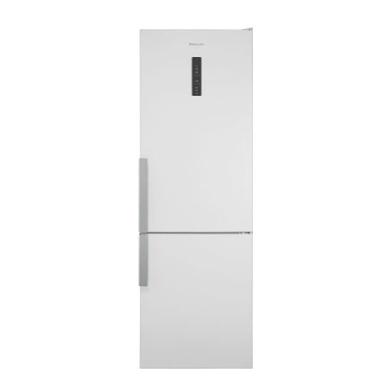
Panasonic NR-BN31AS1 Service Manual
Refrigerator-freezer
Hide thumbs
Also See for NR-BN31AS1:
- Operating instructions manual (68 pages) ,
- Operating instructions manual (68 pages)
Table of Contents
Advertisement
TABLE OF CONTENTS
1 Safety Precautions----------------------------------------------- 2
2 Specifications ----------------------------------------------------- 5
3 Technical Descriptions ----------------------------------------- 6
4 Location of Controls and Components ------------------- 8
5 Installation Instructions ---------------------------------------10
6 Operating Instructions-----------------------------------------12
7 Service Mode -----------------------------------------------------15
8 Troubleshooting Guide ----------------------------------------25
9 Disassembly and Assembly Instructions ---------------31
10 Schematic Diagram ---------------------------------------------43
REFRIGERATOR-FREEZER
Model No.
Model No.
Product-Color
Destination E(Europe Continental) except France
F(France)
B(U.K.)
PAGE
11 Exploded View and Replacement Parts List ----------- 44
© Panasonic Corporation 2013 Unauthorized copying
and distribution is a violation of law.
Order Number GORR1309001CE
NR-BN31AS1
NR-BN31AW1
S:Inox-look
W:White
PAGE
Advertisement
Table of Contents

Related Manuals for Panasonic NR-BN31AS1


Summary of Contents for Panasonic NR-BN31AS1
- Page 1 4 Location of Controls and Components ------------------- 8 5 Installation Instructions ---------------------------------------10 6 Operating Instructions-----------------------------------------12 7 Service Mode -----------------------------------------------------15 8 Troubleshooting Guide ----------------------------------------25 9 Disassembly and Assembly Instructions ---------------31 10 Schematic Diagram ---------------------------------------------43 © Panasonic Corporation 2013 Unauthorized copying and distribution is a violation of law.
-
Page 2: Safety Precautions
1 Safety Precautions... -
Page 5: Specifications
2 Specifications Model NR-BN31AS1 NR-BN31AW1 Total effective volume capacity 307 L Volume capacity Fridge compartment (PC) 222 L Freezer compartment (FC) 85 L External dimensions Width/ Depth/ Height (mm) 600 mm x 637 mm x 1,850 mm side : 20 mm or more... -
Page 6: Technical Descriptions
3 Technical Descriptions Single-compressor cooling system On the basis of temperature checking with sensor in fridge compartment and temperature in freezer compartment, the request for switch-on/off of compressor and Fan Motor is set /deleted Compressor operation In normal mode of operation the compressor functions with the frequency which is prescribed with regard to the actual conditions of regulations. - Page 7 Condition for fridge of freezer compartment (FC) Standard compressor The temperature in freezer compartment can be set from -16°C to -24°C. It operates according to the principle of setting/deleting the request for cooling of freezer compartment. When the temperature in the freezer compartment is equal to or rises above +1 ° C, the compressor and Fan Motor (in normal operation) switch on or, after the expiry of Fan Motor switch-on delay time after defrosting, the Fan Motor of freezer compartment switches on, too.
-
Page 8: Location Of Controls And Components
4 Location of Controls and Components 4.1. Display and Control Panel... - Page 9 4.2. Components...
-
Page 10: Installation Instructions
5 Installation Instructions... -
Page 12: Operating Instructions
6 Operating Instructions 6.1. Setting the temperature 6.1.1. Fridge compartment (PC) 6.1.2. Freezer compartment (FC) 6.1.3. Fresh Zone Crisper 6.2. Functions 6.2.1. Super Cool Mode... - Page 13 6.2.2. Super Freeze Mode 6.2.3. Jet Freeze Mode 6.2.4. ECO Mode...
- Page 14 6.2.5. Holiday Mode 6.2.6. Alarm Mode 6.2.7. Child safety lock...
-
Page 15: Service Mode
7 Service Mode 7.1. Service mode operations General • Service mode is intended for service interventions • In service mode it is possible to select optionally among the outputs • From service mode we always enter normal mode of operation Display Panel A’ssy Display Panel A’ssy on appliance door... - Page 16 7.1.1. How to start 7.1.2. How to stop 7.1.3. Summary of Service Mode...
- Page 17 7.1.4. Service Mode “00” (Main PCB) 7.1.5. Service Mode “01” (Display Panel PCB)
- Page 18 7.1.6. Service Mode “02” (Compressor) 7.1.7. Service Mode “03” (Fan Motor)
- Page 19 7.1.8. Service Mode “04” (Defrost Heater) 7.1.9. Service Mode”05” (PC Damper)
- Page 20 7.1.10. Service Mode “06” (LED Lamp) 7.1.11. Service Mode “07” (PC Temp. Sensor)
- Page 21 7.1.12. Service Mode “08” (FC Temp. Sensor) 7.1.13. Service Mode “09” (Defrost Sensor)
- Page 22 7.2. Measuring Points on Main PCB Box Note: For more detail, refer to the Schematic Diagram on page 44. 7.3. Value of Temperature sensors...
- Page 23 7.4. Operation in case of failure Failure of magnetic switch (LED Lamp) In case of failure of magnetic door switch, the LED Lamp stays switched on for 10 minutes, even when door is closed. During this time the appliance is operating normally and in accordance with the settings. Failure of Temperature Sensors Fridge compartment (PC) Failure of PC sensor in fridge compartment: time algorithm is installed which sets and deletes the request for...
- Page 24 Open door alarm If the door of fridge or freezer compartment is open for more than 2 minutes, the uninterrupted buzzer sound will be heard and the key "1" for cancellation of the alarm will be flashing. When the door is closed, the alarm is canceled. The sound alarm can also be cancelled by pressing the key "1";...
-
Page 25: Troubleshooting Guide
8 Troubleshooting Guide 8.1. Not cooling at all [ Both PC & FC (compressor does not operate)]... - Page 26 8.2. PC is not cooling or poor cooling. [ FC cooling condition is normal]...
- Page 27 8.3. FC is not cooling. [ Compressor operate]...
- Page 28 8.4. Cooling system trouble.
- Page 29 8.5. Communication trouble. 8.6. Temperature sensor trouble.
-
Page 31: Disassembly And Assembly Instructions
9 Disassembly and Assembly Instructions 9.1. Display Panel A’ssy (Display and Control Panel) Before taking any action, please unplug the power supply. To separate Display Panel A’ssy from the door, insert flat screw driver (picture B) into the small opening on the down side in the mid- dle of Display Panel A’ssy. - Page 32 9.2. LED Lamp PC 9.3. Main PCB LED Lamp is installed at the ceiling of PC 1. Main PCB is installed at the upper side of refrigerator. Unhook the hook and push the LED cover to the left. 2. Slide both the Head Panel Cover R and the Head Panel Cover L to remove.
- Page 33 5. While unhooking the rib at the upper center of PCB box 9.4. Air Flow Ins. PC by inserting the screwdriver, draw out the PCB box 1. First, remove the Glass Shelves, Bottle Support and toward you. Drawers, then unscrew the two screws. 6.
- Page 34 3. Remove the PC Duct Upper, then the Air Flow Ins. PC 9.5. Fan Assy can be seen. 1. First, remove the FC Drawers, then unscrew the four screws. 2. Pull the FC Air Duct Cover toward, then the connector of 4.
- Page 35 9.6. Door Switch FC 4. Unhook the hook, then remove the Door Switch FC. 1. First, remove the FC Drawers, Disconnect the connector. 2. Unscrew the screw fixing the Door Switch Cover. Open the Door Switch Cover.
- Page 36 9.7. Replacement of PC temperature sensor 1. Release the latches by screwdriver and remove the cover 4. First crimp the enclosed end splices on conductor of the by hand. new sensor. Place the enclosed thermo-shrinkable bushing. Note: The sensor cover is hooked at two position as Crimp end splices on conductors of cut cable.
- Page 37 9.8. Positions of Temperature Sensors, Thermal Fuse, Defrost Heater and PC Door Switch 9.9. Warning: Make sure the unit is unplugged Changing The doorway Direction...
- Page 38 Remove the Hinge Cover Upper. Remove the PC Door. Remove the PC Door Edge Cover Left. Remove the PC Hinge Cover VC. Disconnect the Display Connector. Slide the Head Panel Cover Right and Head Panel Cover Left then remove its. Unscrew the screws fixing the Upper Hinge.
- Page 39 9. While unhooking the rib at the center of PCB box by using 13. Unscrew the Middle Hinge fixing screw and remove it. the screwdriver Remove the FC Door. 10. Draw out the PCB box toward you and change the elec- tric wire direction.
- Page 40 Lie down the appliance to the back. (min 600mm) Replace the Door Bushing and the FC Door Plug. CAUTION: Do not damage the outer condenser. Remove the PC Door Limiter Right, then install PC Replace the Levelling Leg Right with the Lower Door Limiter Left.
- Page 41 Remove the PC Door Edge Cover Left. Install the Hinge Cover. Install the upper Hinge. Fix the Hinge Cover VC and the PC Door Edge Cover Right. Connect the Display Connector. Remove the display panel by using a small flat-blade screwdriver. (Refer to the Replacement of Display) Screw the Upper Hinge fixing screws.
- Page 42 Remove the Filling Plugs. Unscrew the Handles fixing Torx screws using the Torx screwdriver. Screw the Handles to the right side. Install the Filling Plugs to the left side.
-
Page 43: Schematic Diagram
10 Schematic Diagram... -
Page 44: Exploded View And Replacement Parts List
11 Exploded View and Replacement Parts List 11.1. Interior Parts... - Page 45 11.1.1. Interior Parts List NR-BN31AS1 NR-BN31AW1 Ref. Safety Parts No. Parts Name & Description Remarks 1 CNR-420268 MIDDLE HINGE PLUG 41 CNR-526273 LEVELLING LEG M8X25 41A CNR-697782 LEVELLING LEG M8X40 69 CNR-421098 SCREW CAP 69 CNR-377549 SCREW CAP 100 CNR-662161 SENSOR COVER PC...
- Page 46 11.1.2. Door Assy Parts...
- Page 47 11.1.3. Door Assy Parts List NR-BN31AS1 NR-BN31AW1 Ref. Safety Parts No Parts Name & Description Remarks 26 CNR-435905 NAME PLATE 29 CNR-449209 DOOR PLUG FC 29 CNR-449363 DOOR PLUG FC 83 CNR-442916 DOOR LIMITER 102 CNR-449210 FILLING PLUG 102 CNR-420247 FILLING PLUG...
- Page 48 11.1.4. Multiflow Parts...
- Page 49 11.1.5. Multiflow Parts List NR-BN31AS1 NR-BN31AW1 Ref. Safety Parts No Parts Name & Description Remarks 1360 CNR-408254 PC AIR DUCT LOWER with Air Damper 1361 CNR-436878 AIR FLOW INS PC 1362 CNR-413239 FC AIR DUCT WITH FAN 1364 CNR-408281 FC AIR DUCT COVER...
- Page 50 11.1.6. Unit Parts...
- Page 51 11.1.7. Unit Parts List NR-BN31AS1 NR-BN31AW1 Ref. Safety Parts No. Parts Name & Description Remarks 31 CNR-342001 STARTING RELAY ART.No.******/01 and /02 31 CNR-336728 CONNECTION BOX ART.No.******/03 35 CNR-260862 DRYER WITH TUBE ENDS 43 CNR-410404 CONDENSER 138 CNR-436516 RSO FILTER 165 CNR-199000 CAPACITOR ART.No.******/01 and /02...
Need help?
Do you have a question about the NR-BN31AS1 and is the answer not in the manual?
Questions and answers