Chapters
Table of Contents

Subscribe to Our Youtube Channel
Related Manuals for AGA marvel M60CFWR-SS


Summary of Contents for AGA marvel M60CFWR-SS
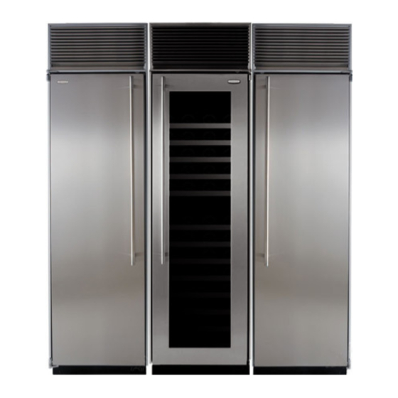
- Page 1 Installation Operation Maintenance Instructions Built In Side by Side by Side Freezer/Wine Cellar/Refrigerator M60CFWR-SS M72CFWR-SS M72CFWR-WS M72CFWR-WP M72CTWT-WS M72CFSWR-WS...
-
Page 2: Table Of Contents
CONTENTS Unpacking the refrigerator/freezer ........3 Important Safety Instructions Tools required ..............3 Warnings and safety instructions appearing in this guide Warranty registration ............4 are not meant to cover all possible conditions and situa- Dimensions for M(XX)CFWR and CFSWR .......5 tions that may occur. Common sense, caution, and care Dimensions for M72CFWR-WP .........6 must be exercised when installing, maintaining, or operat- Dimensions for M72CTWT-WS .........7... -
Page 3: Help Prevent Tragedies
UNPACKING YOUR REFRIGERATOR/FREEZER CAUTION WARNING Help Prevent Tragedies EXCESSIVE WEIGHT HAZARD Child entrapment and suffocation are not problems of the Use two or more people to move product. past. Junked or abandoned refrigerators are still dangerous Failure to do so can result in back or other injury. - even if they sit out for "just a few days". -
Page 4: Warranty Registration
WARRANTY REGISTRATION Cabinet serial plate is on the Power module serial inside top liner toward the right plate is behind the side- grille on the front of the power module- Figure 1 Serial plate locations (M72CFWR shown) Each unit will have two serial plates which will require filling out three warranty registration cards. -
Page 5: Dimensions For M(Xx)Cfwr And Cfswr
AND A GLASS DOOR Electrical Requirements: MODEL "A" "B" "C" "D" "E" Each of the three units will require a M60CFWR-SS 60" (152.4cm) 17" (43.2cm) 17" (43.2cm) 23" (58.4cm) ⁄ " (121.1cm) grounded 115 volt, 60 cycle, single 72" (182.9cm) 23"... -
Page 6: Dimensions For M72Cfwr-Wp
PRODUCT DIMENSIONS FOR M72CFWR-WP WITH 2 SOLID OVERLAY DOORS AND A GLASS OVERLAY DOOR Electrical Requirements: Each of the three units will require a grounded 115 volt, 60 cycle, single phase, 15 amp dedicated circuit. Follow all local building codes when installing electrical and units. 23"... -
Page 7: Dimensions For M72Ctwt-Ws
PRODUCT DIMENSIONS FOR M72CTWT-WS WITH SOLID DOORS AND A GLASS REFRIGERATOR DOOR Electrical Requirements: Each of the three units will require a grounded 115 volt, 60 cycle, single phase, 15 amp dedicated circuit. Follow all local building codes when installing electrical and units. 23"... -
Page 8: Preinstallation Considerations
PRE INSTALLATION CONSIDERATIONS Electrical Requirements: NOTE Provide a 115 volt, 60 cycle, single phase 15 amp, AC receptacle for each of the three units. It is recommended that a separately fused circuit (a time delay fuse or circuit Floor under product MUST be at or above the same level breaker is recommended), serving only each of these ap- of the surrounding finished floor, for ease of installation and pliances, be provided. - Page 9 " (45.1cm) ⁄ " (90.8cm) 54" Figure 5 (137.2cm) Rough in Opening and electrical ⁄ " (199.4cm) locations for the following model: Minimum M60CFWR-SS ⁄ " to 84 ⁄ " (214cm) to (215.6cm) 24" (61cm) ⁄ " (153.7cm) Figure 5...
-
Page 10: Plumbing Requirements
On model M72CTWT-SS two (2) water lines will be re- Model "A" "B" quired as there are two ice makers. This can be accom- M60CFWR-SS ⁄ " (43.8cm) plished by running two separate lines or by providing a tee 20" (50.8cm) to in the line to go to one of the ice makers. -
Page 11: Installing The Cabinet
INSTALLING THE CABINET Corner Installation When planning your rough in opening a 3" removable filler panel is recommended above the grille. To remove the For the door to be opened to a full 90°, a 3" (7.6cm) filler power module from the cabinet the front has to be tilted up will have to be added to the hinge side of the door. -
Page 12: Anti Tip Bracket Considerations
INSTALLING THE CABINET Anti - tip Bracket considerations Before placing the cabinet in opening, the depth of the cut-out opening should be at least 24" (61cm). If the cut-out -Crosswise opening depth is more than 24" (61cm), then a piece of lumber wood must be secured crosswise on the wall into the studs at the height of the anti-tip brackets. -
Page 13: Leveling The Unit
LEVELING THE UNIT Leveling the unit: Unit MUST be installed level in all planes, on a floor that is strong enough to support a fully loaded freezer. See Figure 14. This unit is equipped with front and rear rollers. Rollers will aid during installation. -
Page 14: Installing Three Units Side By Side
INSTALLING THE THREE UNITS SIDE BY SIDE BY SIDE Installing Three Units Side-By-Side By Side: Securing the trim: When three (3) units are installed together, a divider panel Install a wood shim (provided) cut to the dimensions shown needs to be installed between two (2) adjacent power in Section A-A to the side trim of the first cabinet to be modules (refer to Figure 16). -
Page 15: Installing The Power Module
INSTALLING THE POWER MODULE Placing power module on top of cabinet: WARNING Place module on top of the cabinet with rear shoulder screws resting on the locator brackets behind the front slots. Slide module toward the rear of the cabinet until the EXCESSIVE WEIGHT HAZARD rear shoulder screws engage the slots in the rear of the brackets. - Page 16 INSTALLING THE POWER MODULE 18" wide freezer model for (M60CFWR-SS): Plug in the (5) electrical connectors for the lights coming from the cabinet into the (2) power supplies which are at- tached to the power module, see Figure 19. -Light power supplies mounted...
-
Page 17: Installing The Ice Maker Water Valve
INSTALLING THE ICE MAKER WATER VALVE NOTE An inline water filter can be used with this ice maker and is recommended. A shutoff valve should also be installed in the water line. Do not use a self-piercing type valve. Ice Maker (Solenoid) Connection The water valve and the water line fittings are packed inside the cabinet in a plastic bag. -
Page 18: Installing The Grille
INSTALLING THE GRILLE There are three methods that can be used to install the grille. Pick the method that suits your installation. Style 1: Brackets are installed on top of the cabi- net, toward the back, and springs are used to secure the grille. - Page 19 INSTALLING THE GRILLE Style 2 mounting method: Instructions for Installing Grille Brackets This is an optional accessory, order part number S34060-000. Brackets 1. Use the two (91180-000) screws to secure each optional- bracket to the cabinet top. See Figure's 23 and 24. 2.
- Page 20 INSTALLING THE GRILLE Style 3 mounting method: Fasten top of grille to enclosure with screw provided. Cover screw head with snap-on cap. See Figure 25. Cut custom facia panel and mount facia bracket per the instructions on next page. Install facia to grille back by inserting shoulder rivets on back of facia bracket into large ends of teardrop holes.
-
Page 21: Mounting Grille Facia Panel
CUSTOM GRILLE FACIA AND DOOR PANELS Facia Diagram for 72" Wide Models: Mounting grille facia panel for model M72CFWR-WP: Cut the facia panel to the size shown in Figure 26. Drill the three facia bracket screw pilot holes in the back side of the 69"... - Page 22 CUSTOM GRILLE FACIA AND DOOR PANELS Step #1: Remove the Door Custom Door Panel Installation Instructions Support the door at the floor. Determine Wood Screw Requirements for 1. Loosen the set screw in the bullit cap with a ⁄ " hex model M72CFWR-WP: key and remove the bullit cap from the hinge pin by 1.
- Page 23 CUSTOM GRILLE FACIA AND DOOR PANELS CAUTION ⁄ " (56.7cm) Door panels MUST NOT exceed 50 lbs (22.7 kg). Do NOT use glass, mirrors, granite or similar heavy materials for panels. Panels weighing more than 50 lbs (22.7 kg), may cause product damage.
-
Page 24: Hinge And Gasket Adjustments
HINGE AND GASKET ADJUSTMENTS Hinge and Gasket Adjustment Screw- It is possible that doors may become out of adjustment in Door shipment. Gasket- If product is installed slightly "out of level", doors may not line up properly. Check this BEFORE adjusting hinges. NOTE Door gaskets occasionally compress in shipment. -
Page 25: Installing Side Panels
INSTALLING SIDE PANELS AND KICK PLATE Instructions for Fastening Side Panels to ⁄ " freezer (28.4mm) ⁄ " (6.4mm) thick battens- Typical 1. Side panels should be 24" (61cm) deep or 24 ⁄ " (61.7cm) deep when tucked into the front trim. 2. -
Page 26: Installation Checks
INSTALLATION CHECKS/COMMON ERRORS Installation Checks Use and Care Guide: • Anti-tip mounting bracket must be installed correctly CONGRATULATIONS! You are now the proud owner of a and anchored to prevent cabinet from tipping forward. superb, beautiful and durable addition to your kitchen. The following information will help you get the most pleasure •... -
Page 27: Using Your Freezer
USE AND CARE GUIDE Using your freezer: Motor- -Ejector blade Meats, fish and poultry pre-packed in plastic (self-service) wrap can be stored in the freezer for a couple of weeks. -Ice mold For longer freezer storage, wrap food in foil or other vapor- proof, moisture-proof freezer wrap. -
Page 28: Operation Of Your Wine Cellar
USE AND CARE GUIDE Wine cellar features: Setting the control, dual zone models: The upper com- partment has a range from the low forties to the mid sixties. Adjustable temperature control: The temperature control The middle range on the control is approximately 53°F is fully adjustable from the low fourties to the mid sixties. -
Page 29: Temperatures
USE AND CARE GUIDE Condenser cleaning procedure: Temperatures: The condenser is located behind the top grille. It is a part The temperature is automatically controlled by a thermo- of the Power Module on its very right hand side. It has stat. -
Page 30: Energy Saving Tips
ENERGY SAVING TIPS AND PRODUCT SOUNDS Product Sounds: The following suggestions will minimize the Your new refrigerator/freezer may make sounds unfamiliar cost of operating your refrigeration appliance. to you. These sounds normally indicate that the refrigera- tor/freezer is operating correctly. Note that hard surfaces 1. -
Page 31: Obtaining Service
If the product is within the first year warranty pe- If the unit appears to be malfunctioning, read through this riod please call AGA MARVEL Customer Service at manual first. If the problem persists, check the trouble- 800.223.3900 for directions on how to obtain warranty shooting guide below. -
Page 32: Warranty
WARRANTY OF MERCHANTABILITY, ARE LIMITED TO Warranty THE DURATION OF THESE EXPRESS WARRANTIES. During the second year, from date of sale, AGA MARVEL IN NO EVENT SHALL AGA MARVEL BE LIABLE FOR will provide all necessary parts only to repair or replace... - Page 34 www.agamarvel.com 1260 E. VanDeinse St. Greenville MI 48838 800.223.3900 35577-000 EN Rev A All specifications and product designs subject to change without notice. Such revisions do not en- 9/24/13 title the buyer to corresponding changes, improvements, additions, replacements or compensation for previously purchased products.
- Page 35 Instructions d’installation, d’utilisation et d’entretien Construit en Côte à côte à côte Congélateur/Caves à vin/ Réfrigérateur M60CFWR-SS M72CFWR-SS M72CFWR-WS M72CFWR-WP M72CTWT-WS M72CFSWR-WS...
- Page 36 CONTENU Importantes instructions de sécurité Deballage de votre réfrigérateur /congélateur.......3 Outils à avoir sous la main pour l’installation......3 Les avertissements et les instructions de sécurité qui apparais- Enregistrement de la garantie............4 sent dans ce guide n’ont pas la prétention de couvrir toutes les Dimensions M(XX)CFWR and CFSWR ........5 conditions et situations possibles pouvant arriver.
-
Page 37: Deballage De Votre Réfrigérateur /Congélateur
DEBALLAGE DE VOTRE RÉFRIGÉRATEUR /CONGÉLATEUR AVERTISSEMENT ATTENTION RISQUE DE POIDS EXCESSIF Contribuez à éviter des tragédies Utilisez deux personnes ou plus pour bouger et empiler le L’emprisonnement d’enfants et leur asphyxie ne sont pas des produit. Sinon vous pourriez souffrir du dos ou d’une autre problèmes du passé. -
Page 38: Enregistrement De La Garantie
ENREGISTREMENT DE LA GARANTIE La plaque signalétique de l’armoire La plaque signalétique de est en haut de son revêtement intéri- module d’alimentation est eur du côté droit- derrière la grille à l’avant de ce module- Figure 1 Emplacements de plaques signalétiques M72CFWR (montré... -
Page 39: Dimensions M(Xx)Cfwr And Cfswr
DIMENSIONS M(XX)CFWR AND CFSWR Modèle « A » « B » « C » « D » « E » M60CFWR-SS 60 po (152,4cm) 17 po (43,2cm) 17 po (43,2cm) 23 po (58,4cm) ⁄ po (121,1cm) 72 po (182,9cm) 23 po (58,4cm) -
Page 40: Dimensions M72Cfwr-Wp
DIMENSIONS M72CFWR-WP Besoins électriques : Chacun des trois appareils nécessitera un circuit d’alimentation dédié (Secteur monophasé 115 V / 60 Hz / 15 A). Appliquez toutes les normes de construction locales à l’installation de l’électricité et de l’appareil. 23 po 23 po 23 po ⁄... -
Page 41: Dimensions M72Ctwt-Ws
DIMENSIONS M72CTWT-WS Besoins électriques : Chacun des trois appareils nécessitera un circuit d’alimentation dédié (Secteur monophasé 115 V / 60 Hz / 15 A). Appliquez toutes les normes de construction locales à l’installation de l’électricité et de l’appareil. 23 po 23 po 23 po ⁄... -
Page 42: Considérations Pour Avant L'installation
CONSIDÉRATIONS POUR AVANT L’INSTALLATION Besoins électriques REMARQUE Une prise secteur monophasé doit être disponible (115 V / 60 Hz / 15 A). Il est recommandé que le circuit d’alimentation secteur soit dédié à ce seul appareillage, et protégé (fusible temporisé ou La surface d’appui sous le produit DOIT être au même niveau ou disjoncteur). - Page 43 22 po (55,9cm) ⁄ (45,1cm) ⁄ (90,8cm) 54 po Figure 5 (137,2cm) Ouverture brute et emplacements ⁄ électriques pour les produit suivants : (199,4cm) M60CFWR-SS Minimum ⁄ po à 84 ⁄ (214cm) à (215,6cm) 24 po (61cm) ⁄ (153,7cm) Figure 5...
-
Page 44: Besoins En Plomberie
Sur le modèle M72CTWT-SS, deux (2) conduites d’eau seront Modèle « A » « B » nécessaires comme il y a deux machines à glaçons. Cela peut se M60CFWR-SS ⁄ po (43,8cm) réaliser en tirant deux conduites séparées ou en mettant un té sur 20 po (50,8cm) à... -
Page 45: Installation De L'armoire
INSTALLATION DE L’ARMOIRE Quand vous préparez votre ouverture brute, un panneau de rem- Installation en angle plissage de 3 po amovible est recommandé au-dessus de la grille. Pour que la porte puisse complètement s’ouvrir à 90°, un rem- Pour enlever le module d’alimentation de l’armoire, son avant doit plissage de 3 po (7,6 cm) doit être intercalé... -
Page 46: Considérations Sur Le Dispositif Anti-Basculement
INSTALLATION DE L’ARMOIRE Considérations sur le dispositif anti-basculement Avant de placer l’armoire dans son ouverture, la profondeur de la niche doit faire au moins 24 pouces (61 cm). Si cette profondeur est plus importante, il faut fixer une pièce de bois transversale sur -Pièce de le mur dans les poteaux muraux à... -
Page 47: Mise À Niveau De L'armoire
MISE À NIVEAU DE L’ARMOIRE Mise à niveau de l’armoire : L’ensemble DOIT être installé bien d’aplomb sur tous les plans, sur un sol suffisamment solide pour le supporter à pleine charge. Voyez la Figure 14. Cet ensemble est équipé de rouleaux à l’avant et à l’arrière. Ils seront une aide durant l’installation. -
Page 48: Installation Des Trois Appareils
INSTALLATION DES TROIS APPAREILS CÔTE À CÔTE À CÔTE Installation des trois appareils côte à côte à côte : Fixation de garniture : Quand les trois appareils sont installés ensemble, il faut placer Installez une cale en bois (fournie) coupée aux dimensions un panneau séparateur entre les deux modules d’alimentation montrées en coupe A-A sur la garniture latérale de la première (référez-vous à... -
Page 49: Placement Du Module D'alimentation
INSTALLATION DU MODULE D’ALIMENTATION Placement du module d’alimentation en haut de l’armoire : AVERTISSEMENT Placez le module en haut de l’armoire avec les vis à épaulement arrière sur les supports de positionnement derrière les fentes RISQUE DE POIDS EXCESSIF avant. Glissez le module vers l’arrière de l’armoire jusqu’à ce que Utilisez deux personnes ou plus pour bouger et empiler le les vis à... - Page 50 INSTALLATION DU MODULE D’ALIMENTATION 18 po de largeur congélateur modèle for (M60CFWR-SS) : Branchez les (5) connecteurs électriques pour les éclairages ve- nant de l’armoire dans les (2) prises d’alimentation qui sont fixés au module d’alimentation (voyez la Figure 19).
-
Page 51: Installation De La Vanne Sur Le Tube Pour Fabrication De Glaçons
INSTALLATION DE LA VANNE SUR LE TUBE POUR FABRICATION DE GLAÇONS REMARQUE Un filtre en ligne sur la conduite d’eau pour la fabrication de gla- çons est recommandé. Une vanne de coupure peut aussi y être installée. N’utilisez pas de vanne de type auto-perceur. Raccordement de l’électrovanne de la fabrication de glaçons L’électrovanne d’eau et les raccords de conduite sont emballés... -
Page 52: Installation De La Grille
INSTALLATION DE LA GRILLE Il y a trois méthodes utilisables pour installer la grille. Adoptez la méthode qui convient pour votre installation. Style 1 : Des supports sont installés en haut de l’armoire, vers l’arrière, et des ressorts sont utilisés pour retenir la grille. Style 2 : (Optionnel) Des supports sont installés en haut de l’armoire, vers l’avant, et la grille y est fixée avec des vis. - Page 53 INSTALLATION DE LA GRILLE Méthode de montage de style 2 : Instructions pour installer des supports de grille Pour cet accessoire optionnel, commandez la référence S34060-000. 1. Utilisez deux vis (référence 91180-000) pour fixer chaque support sur le haut d’armoire. Voyez les Figures 23 et 24. Supports 2.
- Page 54 INSTALLATION DE LA GRILLE Méthode de montage de style 3 : Fixez la grille du haut sur l’encadrement avec la vis fournie. Cou- vrez la tête de vis avec un capuchon à enfoncer. Voyez la Figure 25. Coupez le tableau personnalisé et montez le support de tableau en suivant les instructions de la page suivante.
-
Page 55: Tableau De Grille Et Panneaux De Porte Personnalisés
TABLEAU DE GRILLE ET PANNEAUX DE PORTE PERSONNALISÉS Montage du panneau de tableau de grille pour Schéma de tableau pour modèles modèle M72CFWR-WP : de largeur 72 po : Selon votre modèle, découpez votre panneau de tableau à la taille montrée en Figure 26. -
Page 56: Instructions D'installation Pour Panneau De Porte
TABLEAU DE GRILLE ET PANNEAUX DE PORTE PERSONNALISÉS Instructions d’installation pour panneau de porte Étape 1 : Enlèvement de la porte personnalisé Déterminez les besoins en vis à bois Supportez la porte à partir du sol. 1. Desserrez la vis de blocage dans le cache boulon avec une modèle M72CFWR-WP : clé... - Page 57 TABLEAU DE GRILLE ET PANNEAUX DE PORTE PERSONNALISÉS ATTENTION ⁄ (56,7cm) Les panneaux de portes ne doivent pas dépasser 50 lbs. (22,7 kg). N’utilisez PAS de verre, miroir, granite ou d’autres matériaux lourds similaires pour les panneaux. Des panneaux pesant plus de 50 lbs.
-
Page 58: Réglages De Charnières Et De Joint
RÉGLAGES DE CHARNIÈRES ET DE JOINT Réglage de charnières et de joint Vis- Il est possible que la porte se désaligne durant l’expédition. Joint de porte- Si un produit est installé en n’étant pas bien d’aplomb, les portes peuvent ne pas être alignées correctement. Vérifiez donc l’aplomb AVANT de régler les charnières. -
Page 59: Installation Des Panneaux Latéraux Et De La Plinthe
INSTALLATION DES PANNEAUX LATÉRAUX ET DE LA PLINTHE Instructions pour fixer les panneaux latéraux sur ⁄ le congélateur Liteaux d’épaisseur (28,4mm) ⁄ po (6,4 mm)- 1. Les panneaux latéraux doivent avoir une profondeur de 24 typique pouces (61cm) (ou 24 ⁄... -
Page 60: Contrôles D'installation
CONTRÔLES D’INSTALLATION/ERREURS HABITUELLES Contrôles d’installation Guide d’utilisation et d’entretien : • Le support de montage anti-basculement doit être installé FÉLICITATIONS! Vous pouvez maintenant vous enorgueillir de correctement et ancré pour éviter que l’armoire ne bascule posséder un ajout superbe et durable dans votre cuisine. Les vers l’avant. -
Page 61: Utilisation De Votre Congélateur
USE AND CARE GUIDE Utilisation de votre congélateur : Moteur- Des viandes, poissons et volailles dans un emballage en plas- -Lame d’éjecteur tique fermé peuvent être entreposés dans le congélateur pour deux semaines. Pour des conservations au froid plus longues, -Moule à... -
Page 62: Caractéristiques De La Cave À Vins
GUIDE D’UTILISATION ET D’ENTRETIEN FÉLICITATIONS! Vous pouvez maintenant vous enorgueillir de Réglage du contrôle, modèles à deux zones : posséder un ajout superbe et durable dans votre cuisine. Les compartiment supérieur a une plage qui va de 5 à 18 degrés informations qui suivent vous aideront à... -
Page 63: Températures
GUIDE D’UTILISATION ET D’ENTRETIEN Procédure de nettoyage du condenseur : Températures : Le condenseur est situé derrière la grille du haut. Il fait partie du La température est automatiquement contrôlée par un thermo- module d’alimentation, complètement à droite. Il comporte des stat. -
Page 64: Conseils Pour Économie D'énergie
CONSEILS POUR ÉCONOMIE D’ÉNERGIE ET BRUITS EN PROVENANCE DU RÉFRIGÉRATEUR Les suggestions suivantes vont minimiser le coût 3) Le ventilateur d’évaporateur va également s’activer/ se désactiver avec le compresseur afin de fournir du de fonctionnement de votre appareil de refroid- refroidissement dans les compartiments d’entreposage. -
Page 65: Dépannage
Si le produit est encore dans sa première année de garan- par bien relire son manuel. Si le problème persiste, consultez tie, veuillez appeler le service à la clientèle d’AGA MARVEL le guide de dépannage qui suit. Identifiez le problème dans ce au 800.223.3900 pour avoir des instructions sur la façon... -
Page 66: Garantie
Ensemble de l’appareil – Garantie limitée d’un an LES GARANTIES DÉFINIES DANS CE DOCUMENT AGA MARVEL garantit qu’il fournira toutes les pièces et la main- SONT LES SEULEES ACCORDÉES PAR AGA d'œuvre nécessaires pour réparer ou remplacer, au domicile de MARVEL. - Page 68 www.agamarvel.com 1260 E. VanDeinse St. Greenville MI 48838 800.223.3900 35577-000 FR Rev A Toutes les spécifications et les conceptions des produits sont sujettes à des changements sans 10/4/13 préavis. De telles révisions ne donnent aucun droit pour l’acheteur de produits antérieurs à béné- ficier de ces changements, améliorations, ajouts, remplacements, ni de recevoir une compensation.
Need help?
Do you have a question about the M60CFWR-SS and is the answer not in the manual?
Questions and answers