Table of Contents
Advertisement
577D- - - - A
EVOLUTIONR
15 SEER SINGLE- - PACKAGED AIR CONDITIONER AND GAS FURNACE
SYSTEM WITH PURONR (R- - 410A) REFRIGERANT
SINGLE PHASE
2- - 5 NOMINAL TONS (SIZES 24- - 60)
CAUTION
!
EQUIPMENT OPERATION HAZARD
Failure to follow this caution may result in improper unit
operation.
OAT sensor must be field installed. See Accessory
Installation for more details.
CAUTION
!
EQUIPMENT OPERATION HAZARD
Failure to follow this caution may result in improper unit
operation.
This Evolutionr unit is designed for use with an Evolution
User Interface.
NOTE:
Read the entire instruction manual before starting the
installation.
TABLE OF CONTENTS
. . . . . . . . . . . . . . . . . . . . . . . . . . . . . . . . . . .
. . . . . . . . . . . . . . . . . . . . . . . . . . . . . . . . . .
. . . . . . . . . . . . . . . . . . . . . . . . . . . . . . . . . . . .
. . . . . . . . . . . . . . . . . . . . . . . . . . . . . . . . .
. . . . . . . . . . . . . . . . . . . . . . . . . . . . . . .
. . . . . . . . . . . . . . . . . . . . . . . . . . . . . . . . . . . . . .
. . . . . . . . . . . . . . . . . . . . . . . . . . . . . . . . . . . . .
. . . . . . . . . . . . . . . . . . . . . . . . . . . . . . . . .
. . . . . . . . . . . . . . . . . . . . . . . . . . . . . . . . .
. . . . . . . . . . . . . . . . . . . . . . . . . . . . . . . . . . . . . .
. . . . . . . . . . . . . . . . . . . . . . . . . . . .
. . . . . . . . . . . . . . . . . . . . . . . . . . . . . . . . . .
. . . . . . . . . . . . . . . . . . . . . . . . . . . . . . . . .
. . . . . . . . . . . . . . . . . . . . . . . . . . . .
. . . . . . . . . . . . . . . . . . . . . . . . . . . . . . . . . . .
. . . . . . . . . . . . . . . . . . . . . . . . . . . . . . . . . . . . .
. . . . . . . . . . . . . . . . . . . . . . . . . . . . .
. . . . . . . . . . . . . . . . . . . . . . . . . . . . . .
Installation Instructions
. . . . . . . . . . . . . . . . . . . . . . . . .
. . . . . . . . . . . . . . . . .
. . . . . . . . . . . . . . . . . . . . . . . . . . .
. . .
. . . . . . . . . . . . . . . . . . . . .
. . . . . . . . . . . . . . . . . . . . . . . .
. . . . . . . . . . . . . . . . . . . . . . . .
. . . . . . . . . . . . . . . . . . . . .
. . . . . . . . . . .
. . . . . . . . . . . . . . . . . . . . .
. . . . . . . . . . . . . .
. . . . . . . . . . . . . . . . . . .
. . . . . . . . . . . . . . . . . . . . . . . . .
PAGE
2
2
2- -13
2
2
2
. . . . . . . . . . . . . . . . . . . . . . . . . . . . . . . . . . . . . . . .
2
2
3
3
3
3
9
9
10
10
11
11
12
12
12
12
13
13
13
16
16- -29
16
23
28
28
1
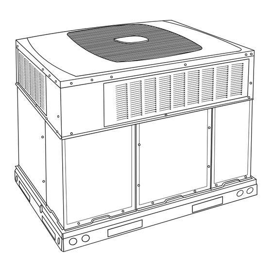
Fig. 1 - - Unit 577D- -- -A
. . . . . . . . . . . . . . . . . . . . . . . . . . . . . .
. . . . . . . . . . . . . . . . . . . . . . . . . . . . . . . . . . . . .
. . . . . . . . . . . . . . . . . . . . . . . . . . . . .
. . . . . . . . . . . . . . . . . . . .
. . . . . . . . . . . . . . . . . . . . . . . . . . . . . . . .
. . . . . . . . . . . . . . . . . . . . . . . . . . . . . .
. . . . . . . . . . . . . . . . . . . . . . . . . . . . . . . . . . .
. . . . . . . . . . . . . . . . . . . . . . . . . . . . . . . . . . . . .
. . . . . . . . . . . . . . . . . . . . . . . . . . . . . . . . . . .
. . . . . . . . . . . . . . . . . . . . . . . . . . . . . . . . . . . .
. . . . . . . . . . . . . . . . . . . . . . . . . . . .
. . . . . . . . . . . . . . . . . . . . . . . . . . . . . . . . . . . . .
. . . . . . . . . . . . . . . . . . . . . . .
. . . . . . . . . . . . . . . . . . . . . . . . . . . . . . . . .
. . . . . . . . . . . . . . . . . . . . . . . . . . . . . . . . . . .
. . . . . . . . . . . . . . . . . . . . . . . . . . . . . . . . .
. . . . . . . . . . . . . . . . . . . . . . . . . . . .
. . . . . . . . . . . . . . . . . . . . . . . . . . . .
®
. . . . . . . . . . . . . . . . . . . . . . . . . . . . . . . .
. . . . . . . . . . . . . . . . . . . . . . . . . . . . . . . . . . . .
. . . . . . . . . . . . . . . . . . . . . . . . . . . . . . . . .
. . . . . . . . . . . . . . . . . . . . . . . . . .
. . . . . . . . . . . . . . .
. . . . . . . . . . . . . . . . . . . . . . . . . . . . . .
. . . . . . . . . . . . . . . . . . . . . . . . . . . . . . . . . . .
. . . . . . . . . . . . . . . . . . . . . . . .
. . . . . . . . . . . . . . . . . . . . . . . . . . . .
A09032
. . . . . .
28
. . . . . . . . . . .
28
29
29
29
29
. .
29
31- -34
31
31
31
31
31
31
32
. . . . .
32
32
32
33
33
33
33
33
. . . . . . . .
33
33
33
33
. . . .
33
34
34
34
35
35
39
Advertisement
Table of Contents
Troubleshooting

Related Manuals for Bryant EVOLUTION 577D----A


Summary of Contents for Bryant EVOLUTION 577D----A
-
Page 1: Table Of Contents
577D- - - - A EVOLUTIONR 15 SEER SINGLE- - PACKAGED AIR CONDITIONER AND GAS FURNACE SYSTEM WITH PURONR (R- - 410A) REFRIGERANT SINGLE PHASE 2- - 5 NOMINAL TONS (SIZES 24- - 60) Installation Instructions CAUTION EQUIPMENT OPERATION HAZARD Failure to follow this caution may result in improper unit operation. -
Page 2: 577D
INTRODUCTION The 577D- -- -A packaged unit is a fully self- -contained combination Category I gas heating/electric air conditioner designed for outdoor installation (See Fig. 1). Standard units are shipped in a horizontal- -discharge configuration for installation on a rooftop, or on cement slab (See Fig. -
Page 3: Slab Mount
MAXIMUM ALLOWABLE DIFFERENCE in. (mm) (6.35) (6.35) Fig. 2 - - Unit Leveling Tolerances Installation on older “G” series roof curbs. Two accessory kits are available to aid in installing a new “G” series unit on an old “G” roof curb. 1. - Page 4 HVAC unit HVAC unit basepan base rails Anchor screw Flashing field supplied Roofing material field supplied Cant strip field supplied *Provided with roofcurb ROOF CURB DETAIL LARGE CURB UNIT CATALOG SIZE NUMBER (mm) CPRFCURB010A00 Small (279) Large CPRFCURB011A00 (356) CPRFCURB012A00 (279) Large CPRFCURB013A00...
- Page 5 A09556 Fig. 5 - - 577D- -- -A24- -30 Unit Dimensions...
- Page 6 A09557 Fig. 6 - - 577D- -- -A36- -60 Unit Dimensions...
- Page 7 UNIT SIZE 24040 NOMINAL COOLING CAPACITY (ton) NOMINAL HEATING CAPACITY (Btu) 40,000 SHIPPING WEIGHT (lb) (kg) COMPRESSORS Quantity REFRIGERANT: PURON (R--- 410A) 10.1 Quantity (lb) (kg) REFRIGERANT METERING DEVICE Size 2 Ton OUTDOOR COIL Rows...Fins/in. 2...21 Face Area (sq ft) 13.6 OUTDOOR FAN Nominal Cfm...
- Page 8 UNIT SIZE NOMINAL COOLING CAPACITY (ton) NOMINAL HEATING CAPACITY (Btu) SHIPPING WEIGHT (lb) (kg) COMPRESSORS Quantity REFRIGERANT: PURON (R--- 410A) Quantity (lb) (kg) REFRIGERANT METERING DEVICE Size OUTDOOR FAN Nominal Cfm Diameter (in.) (mm) Motor Hp (Rpm) OUTDOOR COIL Rows...Fins/in. Face Area (sq ft) INDOOR COIL Rows...Fins/in.
-
Page 9: Rigging/Lifting Of Unit
CAUTION - NOTICE TO RIGGERS PRUDENCE - AVIS AUX MANIPULATEUR ACCESS PANELS MUST BE IN PLACE WHEN RIGGING. PANNEAUX D'ACCES DOIT ÊTRE EN PLACE POUR MANIPULATION. Use top skid as spreader bar. / Utiliser la palette du haut comme barre de répartition SEE DETAIL A VOIR DÉTAIL A CABINET... -
Page 10: Configuring Units For Downflow (Vertical) Discharge
2. Avoid abrupt duct size increases and reductions. Abrupt change in duct size adversely affects air performance. IMPORTANT: Use flexible connectors between ductwork and unit to prevent transmission of vibration. Use suitable gaskets to ensure weather tight and airtight seal. When electric heat is installed, use fireproof canvas (or similar heat resistant material) connector between ductwork and unit discharge connection. -
Page 11: Install Flue Hood
the outlet of the trap is at least 1 in. (25 mm) lower than the drain- -pan condensate connection to prevent the pan from overflowing. Prime the trap with water. When using a gravel apron, make sure it slopes away from the unit. If the installation requires draining the condensate water away from the unit, install a field- -supplied 2- -in. -
Page 12: Install Electrical Connections
Fig. 10 - - Sediment Trap WARNING FIRE OR EXPLOSION HAZARD Failure to follow this warning could result in fire, explosion, personal injury, death and/or property damage. S Connect gas pipe to unit using a backup wrench to avoid damaging gas controls. S Never purge a gas line into a combustion chamber. -
Page 13: Routing Control Power Wires
NOMINAL INTERNAL IRON PIPE DIAMETER SIZE (IN.) (IN.) (3.0) (6.1) .622 .824 1.049 1--- 1/4 1.380 1400 1--- 1/2 1.610 2100 1460 *Capacity of pipe in cu ft of gas per hr for gas pressure of 0.5 psig or less. Pressure drop of 0.5 ---IN. W.C. (based on a 0.60 specific gravity gas). Refer to Table 2 and NFPA 54/ANSI Z223.1. - Page 14 Fig. 11 - - Typical Installation GROUND SCREW (IN SPLICE BOX) GROUND LEAD SINGLE-PHASE CONNECTIONS TO DISCONNECT PER NEC NOTE: Use copper wire only. LEGEND NEC – National Electrical Code Field Wiring Splice Connections Fig. 12 - - Line Power Connections A09075 A06299...
- Page 15 HP/AC BOARD FURNACE BOARD Fig. 13 - - Control Plate Fig. 14 - - Control Voltage Wiring Connections A09108 A06357...
-
Page 16: Pre- -Start- -Up
Careful use of information displayed will reduce the need for extensive manual troubleshooting. Both the furnace and heat pump (HP)/air conditioner (AC) boards have an amber LED and a green LED. On the HP/AC board, these are located near the System Communications connector (ABCD) (lower right corner of the HP/AC board as installed in the unit). - Page 17 emergency heating or cooling operation using a common thermostat and the terminal strip connections on the two control boards (See Non- -Communicating Emergency Cooling/Heating Mode) and will display Status Code 16, System Communication Fault, on amber STATUS LED. No further troubleshooting information will be available at UI until communications are re- -established.
- Page 18 A10217C Fig. 16 - - Connection Wiring Schematic- -577D- -- -A Single Phase Gas Inputs 040, 060, 090 kBtu/hr...
- Page 19 A10217L Fig. 16 Cont. - - Ladder Wiring Schematic- -577D- -- -A Single Phase Gas Inputs 040, 060, 090 kBtu/hr...
- Page 20 A10219C Fig. 17 - - Connection Wiring Schematic- -577D- -- -A Single Phase Gas Inputs 115, 130 kBtu/hr...
- Page 21 A10219L Fig. 17 Cont. - - Ladder Wiring Schematic- -577D- -- -A Single Phase Gas Inputs 115, 130 kBtu/hr...
- Page 22 UTILITY RELAY UTILITY SIGNAL OPEN RELAY SUPPLIED BY UTILITY PROVIDER STATUS CODE 21 - - GAS HEATING LOCKOUT Control will NOT auto reset. Check for mis- -wired gas valve or defective control (valve relay). STATUS CODE 22 - - ABNORMAL FLAME- -PROVING SIGNAL Flame is proved while gas valve is de- -energized.
-
Page 23: Sequence Of Operation
100_F (38°C). S There is no time delay between air conditioner staging from low to high and from high to low capacity; the compressor will change from low to high and from high to low capacity as demand... - Page 24 115,000 577DNWA60115 577DNWA48130 130,000 577DNWA60130 Airflow delivery values for external static pressure values of up to 1 IN. W.C. Table 4 – Heat Pump/Air Conditioner Board Status Codes OPERATION FAULT Standby – no call for unit operation None Standard Thermo-...
-
Page 25: Dehumidification Mode
EVOLUTION CONTROLLED LOW AMBIENT COOLING NOTE: When this unit is operating below 55_F (13°C) outdoor temperature, provisions must be made for low ambient operation. This unit is capable of low ambient cooling down to 0_F (- -18°C). ONLY when using the Evolution control. A low ambient kit is not required, and the outdoor fan motor does not need to be replaced for Evolution controlled low ambient operation. - Page 26 WARNING CARBON MONOXIDE POISONING HAZARD Failure to follow this warning could result in personal injury and/or death. If the manifold pressure and/or gas rate is not properly adjusted on HI and LO stages, excess carbon monoxide can be produced. WARNING FIRE AND UNIT DAMAGE HAZARD Failure to follow this warning could result in personal injury or death and/or property damage.
-
Page 27: Check Burner Flame
a. 129 sec. to complete one revolution b. 3600/129 = 27.9 c. 27.9 x 2 = 55.8 ft of gas flow/hr. d. 55.8 x 1050 = 58,590 Btuh input. In this example, the nominal input rate for low stage is 58,500 Btu/hr, so the low stage manifold pressure is correctly set. -
Page 28: Check For Refrigerant Leaks
BURNER FLAME Fig. 21 - - Monoport Burner LIMIT SWITCHES Normally closed limit switch (LS) completes the control circuit. Should the leaving- -air temperature rise above the maximum allowable temperature, the limit switch opens and the control circuit “breaks.” Any interruption in the control circuit instantly closes the gas valve and stops gas flow to the burners. -
Page 29: Refrigerant Charge
HEATING INPUT (BTU/HR)* NUMBER OF NUMBER OF ORIFICES ORIFICES High Stage Low Stage 40,000 26,000 60,000 39,000 90,000 58,500 115,000 75,000 130,000 84,500 *Cubic ft of natural gas per hour for gas pressures of .5 psig (14 IN. W.C.) or less and a pressure drop of .5 IN. W.C. (based on a .60 specific gravity gas). Ref: Table 6.2 (b) NPFA 54 / ANSI Z223.1 ---2009. - Page 30 A06360 Fig. 22 - - Non- -Communicating Emergency Cooling/Heating Wiring Connections A09109 Fig. 23 - - Cooling Charging Table- -Subcooling...
-
Page 31: Maintenance
MAINTENANCE To ensure continuing high performance, and to minimize the possibility of premature equipment failure, periodic maintenance must be performed on this equipment. This packaged unit should be inspected at least once each year by a qualified service person. To troubleshoot unit, refer to Table 9 and 10, Troubleshooting Chart. -
Page 32: Inducer Pressure Switch
8. Partially slide the burner rack out of the unit (see Fig. 25 and 26). Remove ignitor and sensor wires at the burner as- sembly. Remove wires to rollout switch. 9. Slide the burner rack out of the unit (See Fig. 25 and 26). 10. -
Page 33: Refrigerant Circuit
After inspecting the electrical controls and wiring, replace all the panels. Start the unit, and observe at least one complete cooling cycle to ensure proper operation. If discrepancies are observed in operating cycle, or if a suspected malfunction has occurred, check each electrical component... -
Page 34: Liquid- -Line Filter Drier
Exposure, even if immediately cleaned up, may cause embrittlement (leading to cracking) to occur in one year or more. When performing any service that may risk exposure of compressor oil to the roof, take appropriate precautions to protect roofing. Procedures which risk oil leakage include, but are not limited to, compressor replacement, repairing refrigerant leaks, and replacing refrigerant components such as filter drier, pressure switch, metering device, coil, accumulator, or reversing valve. -
Page 35: Final Checks
exists, the thermal protector is open. The control de- -energizes the compressor contactor for 15 minutes, but continues to operate the outdoor fan. The control Status LED will flash the appropriate code shown in Table 4. After 15 minutes, with a call for low or high stage cooling, the compressor contactor is energized. -
Page 36: Care And Maintenance
CARE AND MAINTENANCE For continuing high performance and to minimize possible equipment failure, periodic maintenance must be performed on this equipment. Frequency of maintenance may vary depending upon geographic areas, such as coastal applications. See Users Manual for information. - Page 37 S When system must be opened for service, break vacuum with dry nitrogen and replace filter driers. S Do not vent Puron into the atmosphere. S Observe all warnings, cautions, and bold text. S Do not leave Puron suction line driers in place for more than 72 hrs. AIR CONDITIONER WITH PURON...
- Page 38 SYMPTOM Compressor and outdoor fan will not start Compressor will not start but condenser fan runs Compressor cycles (other than normally sat- isfying) cooling/heating calls Compressor operates continuously Excessive head pressure Head pressure too low Excessive suction pressure Suction pressure too low IFM does not run IFM operation is intermittent Table 9 –...
- Page 39 Table 10 – Troubleshooting Chart - - Gas Furnace Operation SYMPTOM Burners will not ignite Inadequate heating Poor flame characteristics CAUSE Water in gas line No power to unit No 24--v power supply to control circuit Mis--wired or loose connections Misaligned spark electrodes No gas at main burners Inducer pressure switch not closing...
-
Page 40: Start- -Up Checklist
{ Measured at liquid line leaving condenser. E2010 Bryant Heating & Cooling Systems D 7310 W. Morris St. D Indianapolis, IN 46231 Manufacturer reserves the right to discontinue, or change at any time, specifications or designs without notice and without incurring obligations.
Need help?
Do you have a question about the EVOLUTION 577D----A and is the answer not in the manual?
Questions and answers