Advertisement
Quick Links
577C--(E, F) Ultra Low NOx
Legacy™ 14 SEER Single-Packaged Air Conditioner
and Gas Furnace System with Puron® (R-410A)
Refrigerant
Single Phase 2-5 Nominal Tons (Sizes 24-60)
Three Phase 3-5 Nominal Tons (Sizes 36-60)
IMPORTANT: Effective January 1, 2015, all split system and packaged
air conditioners must be installed pursuant to applicable regional
efficiency standards issued by the Department of Energy.
NOTE:
Read the entire instruction manual before starting the
installation.
NOTE:
Installer: Make sure the Owner's Manual and Service
Instructions are left with the unit after installation.
Table of Contents
Safety Considerations . . . . . . . . . . . . . . . . . . . . . . . . . . . . . . . . . . . . . . . 1
Introduction. . . . . . . . . . . . . . . . . . . . . . . . . . . . . . . . . . . . . . . . . . . . . . . 2
Receiving and Installation . . . . . . . . . . . . . . . . . . . . . . . . . . . . . . . . . . . 2
Pre-start-up . . . . . . . . . . . . . . . . . . . . . . . . . . . . . . . . . . . . . . . . . . . . . . 13
Start-up . . . . . . . . . . . . . . . . . . . . . . . . . . . . . . . . . . . . . . . . . . . . . . . . . 13
Maintenance . . . . . . . . . . . . . . . . . . . . . . . . . . . . . . . . . . . . . . . . . . . . . 28
Troubleshooting . . . . . . . . . . . . . . . . . . . . . . . . . . . . . . . . . . . . . . . . . . 32
Start-up Checklist . . . . . . . . . . . . . . . . . . . . . . . . . . . . . . . . . . . . . . . . . 32
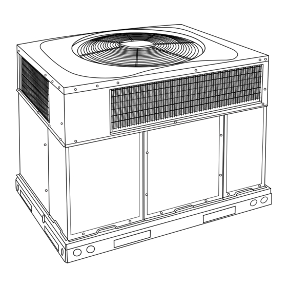
Fig. 1 - Unit 577C
Safety Considerations
Improper installation, adjustment, alteration, service maintenance, or use
can cause explosion, fire, electrical shock, or other conditions which
may cause death, personal injury, or property damage. Consult a
qualified installer, service agency, or your distributor or branch for
information or assistance. The qualified installer or agency must use
factory-authorized kits or accessories when modifying this product.
Refer to the individual instructions packaged with the kits or accessories
when installing.
Follow all safety codes. Wear safety glasses, protective clothing, and
work gloves. Have a fire extinguisher available. Read these instructions
thoroughly and follow all warnings or cautions included in literature and
Installation Instructions
A170030
attached to the unit. consult local building codes, the current editions of
the National Fuel Gas Code (NFGC) NFPA 54/ANSI Z223.1, and the
National Electrical Code (NEC) NFPA 70.
In Canada refer to the current editions of the National Standards of
Canada CAN/CSA-B149.1 and .2 Natural Gas and Propane Installation
codes, and Canadian Electrical Code CSA C22.1
Recognize safety information. This is the safety-alert symbol
you see this symbol on the unit and in instructions or manuals, be alert to
the potential for personal injury. Understand these signal words:
DANGER, WARNING, and CAUTION. These words are used with the
safety-alert symbol. DANGER identifies the most serious hazards which
will result in severe personal injury or death. WARNING signifies
hazards which could result in personal injury or death. CAUTION is
used to identify unsafe practices which may result in minor personal
injury or product and property damage. NOTE is used to highlight
suggestions which will result in enhanced installation, reliability, or
operation.
WARNING
!
CARBON MONOXIDE POISONING HAZARD
Failure to follow this warning could result in personal injury and/or
death.
Carbon Monoxide (CO) is a colorless, odorless, and tasteless poisonous
gas that can be fatal when inhaled. Follow all installation, maintenance,
and service instructions. See additional information below regarding
the installation of a CO Alarm.
Most states in the USA and jurisdictions in Canada have laws that
require the use of Carbon Monoxide (CO) alarms with fuel burning
products. Examples of fuel burning products are furnaces, boilers, space
heaters, generators, water heaters, stoves/ranges, clothes dryers,
fireplaces, incinerators, automobiles, and other internal combustion
engines. Even if there are no laws in your jurisdiction requiring a CO
Alarm, it's highly recommended that whenever any fuel burning product
is used in or around the home or business that the dwelling be equipped
with a CO Alarm(s). The Consumer Product Safety Commission
recommends the use of CO Alarm(s). The CO Alarm(s) must be
installed, operated, and maintained according to the CO Alarm
manufacturer's instructions. For more information about Carbon
Monoxide, local laws, or to purchase a CO Alarm only, please visit the
following website
https://www.kidde.com
. When
Advertisement

Related Manuals for Bryant 577C-E Series


Summary of Contents for Bryant 577C-E Series
-
Page 1: Table Of Contents
577C--(E, F) Ultra Low NOx Legacy™ 14 SEER Single-Packaged Air Conditioner and Gas Furnace System with Puron® (R-410A) Refrigerant Single Phase 2-5 Nominal Tons (Sizes 24-60) Three Phase 3-5 Nominal Tons (Sizes 36-60) Installation Instructions IMPORTANT: Effective January 1, 2015, all split system and packaged attached to the unit. -
Page 2: Introduction
577C--(E, F) Ultra Low NOx: Installation Instructions If the unit is to be mounted on a curb in a downflow application, review CAUTION Step 9 to determine which method is to be used to remove the downflow panels before rigging and lifting into place. The panel removal process ELECTRICAL SHOCK HAZARD may require the unit to be on the ground. - Page 3 577C--(E, F) Ultra Low NOx: Installation Instructions Only trained, qualified crane operators and ground support staff should handle and install this equipment. When working with this equipment, observe precautions in the literature, OPTIONAL OPTIONAL on tags, stickers, and labels attached to the equipment, and any other RETURN SUPPLY safety precautions that might apply.
- Page 4 577C--(E, F) Ultra Low NOx: Installation Instructions A200166 Fig. 3 – 24-36 Unit Dimensions Manufacturer reserves the right to change, at any time, specifications and designs without notice and without obligations.
- Page 5 577C--(E, F) Ultra Low NOx: Installation Instructions A200160 Fig. 4 – 42-60 Unit Dimensions Manufacturer reserves the right to change, at any time, specifications and designs without notice and without obligations.
- Page 6 577C--(E, F) Ultra Low NOx: Installation Instructions Dashed lines show cross support location for large basepan units. HVAC unit HVAC unit basepan base rails Sealing Gasket Roofcurb Anchor screw Wood nailer* Flashing field supplied Roofcurb* Insulation (field supplied) Roofing material field supplied Cant strip field supplied...
- Page 7 577C--(E, F) Ultra Low NOx: Installation Instructions CAUTION - NOTICE TO RIGGERS PRUDENCE - AVIS AUX MANIPULATEUR ACCESS PANELS MUST BE IN PLACE WHEN RIGGING. PANNEAUX D'ACCES DOIT ÊTRE EN PLACE POUR MANIPULATION. Use top skid as spreader bar. / Utiliser la palette du haut comme barre de répartition DUCTS MINIMUM HEIGHT: 36"...
- Page 8 Table 1 – Physical Data Unit Size 24040 24060 30040 30060 36060 42060 42090 48090 60090 NOMINAL CAPACITY (ton) 2-1/2 2-1/2 3-1/2 3-1/2 SHIPPING WEIGHT lb. SHIPPING WEIGHT (kg) COMPRESSOR / QUANTITY Rotary / 1 Scroll / 1 REFRIGERANT (R-410A) Quantity lb.
- Page 9 577C--(E, F) Ultra Low NOx: Installation Instructions Table 2 – Maximum Gas Flow Capacity † Length of Pipe ft (m) Nominal Internal Iron Pipe Diameter Size (in.) (in.) (12) (15) (18) (21) (24) (27) (30) (38) (46) (53) (61) .622 —...
- Page 10 577C--(E, F) Ultra Low NOx: Installation Instructions Use a minimum of one hanger every 6 ft (1.8 m). For pipe sizes WARNING larger than 1/2 in., follow recommendations of national codes. 3. Apply joint compound (pipe dope) sparingly and only to male FIRE OR EXPLOSION HAZARD threads of joint when making pipe connections.
- Page 11 577C--(E, F) Ultra Low NOx: Installation Instructions side tabs. These plastic knockouts are held in place with tabs use vapor barrier in accordance with latest issue of Sheet Metal and similar to an electrical knockout. Discard plastic knockout covers. Air Conditioning Contractors National Association (SMACNA) and Air Conditioning Contractors of America (ACCA) minimum 5.
- Page 12 577C--(E, F) Ultra Low NOx: Installation Instructions NOTE: Field supplied disconnect switch box should be positioned so Locate six (seven for 3-phase) 18-gage wires leaving control box. These that it does not cover up any of the unit gas combustion supply air low-voltage connection leads can be identified by the colors red, green, louvers.
-
Page 13: Pre-Start-Up
577C--(E, F) Ultra Low NOx: Installation Instructions Pre-start-up a. Make sure gas line is free of air. Before lighting the unit for the first time, perform the following with the gas valve in the OFF WARNING position: NOTE: If the gas supply pipe was not purged before connecting the unit, it will be full of air. - Page 14 577C--(E, F) Ultra Low NOx: Installation Instructions Table 3 – Altitude Derate Multiplier for U.S.A. Derate Multiplier † Altitude ft Percent of Derate ‡ Factor 0-2000 1.00 (0-610) *. In Canada see Canadian Altitude Adjustment. †. Altitude of 2001 ft and above is not allowed. ‡.
- Page 15 577C--(E, F) Ultra Low NOx: Installation Instructions If larger adjustments are required, change main burner orifices following 4. 87.8 x 1050 = 92,190 Btuh input the recommendations of national and local codes. If the desired gas input is 89,000 Btuh, only a minor change in the NOTE: All other appliances that use the same meter must be turned off manifold pressure is required.
- Page 16 577C--(E, F) Ultra Low NOx: Installation Instructions CONNECTION WIRING DIAGRAM DANGER: ELECTRICAL SHOCK HAZARD DISCONNECT POWER BEFORE SERVICING SCHEMATIC 208/230-1-60 IF USED CONT CAP 1 FIELD SUPPLY SEE NOTE 8 POWER EQUIP GND UNIT ONLY MAXIMUM WIRE GRN/YEL SIZE 2 AWG COMP TO IGC SEE NOTE 4/5...
- Page 17 577C--(E, F) Ultra Low NOx: Installation Instructions LADDER WIRING DIAGRAM DANGER: ELECTRICAL SHOCK HAZARD DISCONNECT POWER BEFORE SERVICING USE COPPER CONDUCTORS ONLY LEGEND FIELD SUPPLY EQUIP GND 208/230 VAC. 60 HZ. 1PH C;21 FIELD SPLICE CONT COMPRESSOR CONTACTOR C;11 EQUIP EQUIPMENT TERMINAL (MARKED) FLAME SENSOR...
- Page 18 577C--(E, F) Ultra Low NOx: Installation Instructions CONNECTION WIRING DIAGRAM DANGER: ELECTRICAL SHOCK HAZARD DISCONNECT POWER BEFORE SERVICING SCHEMATIC 208/230-3-60 IF USED CONT CAP 1 FIELD SUPPLY SEE NOTE 8 POWER COMP EQUIP GND GRN/YEL UNIT ONLY MAXIMUM WIRE SIZE 2 AWG 1 2 3 4 5 TO IGC SEE NOTE 4/5...
- Page 19 577C--(E, F) Ultra Low NOx: Installation Instructions LADDER WIRING DIAGRAM DANGER: ELECTRICAL SHOCK HAZARD DISCONNECT POWER BEFORE SERVICING USE COPPER CONDUCTORS ONLY LEGEND FIELD SUPPLY EQUIP GND 208/230 VAC. 60 HZ. 3PH EQUIP EQUIPMENT FIELD SPLICE C;21 FLAME SENSOR C;11 TERMINAL (MARKED) GROUND HIGH PRESSURE SWITCH...
- Page 20 577C--(E, F) Ultra Low NOx: Installation Instructions Normal Operation Table 6 – LED Indications An LED (light-emitting diode) indicator is provided on the integrated Status Code LED Indication gas unit controller (IGC) to monitor operation. The IGC is located by Normal Operation removing the control access panel (see Fig.
- Page 21 577C--(E, F) Ultra Low NOx: Installation Instructions is more than 2°F (1.1°C) lower than required liquid line WARNING temperature. NOTE: If the problem causing the inaccurate readings is a refrigerant EXPLOSION HAZARD leak, refer to the Check for Refrigerant Leaks section. Failure to follow this warning could result in Indoor Airflow and Airflow Adjustments death, serious personal injury, and/or property...
- Page 22 577C--(E, F) Ultra Low NOx: Installation Instructions Dehumidification Cooling Fan Speed Set-up: 2-Pin Terminal IMPORTANT: Dehumidification control must open control circuit on humidity rise above set point. Use of the dehumidification cooling fan speed requires use of either a 24 VAC dehumidistat or a thermostat which includes control of a 24 VAC dehumidistat connection.
- Page 23 577C--(E, F) Ultra Low NOx: Installation Instructions Table 8 – Cooling Charging Chart Superheat charging table is derived from optimum performance point. (95°F [35°C] outdoor ambient and (80°F [27°C] dry bulb; 67°F [19°C] wet bulb indoor condition.) Where a dash(--) appears do not attempt to check charge or charge unit under these conditions using the superheat method.
- Page 24 Table 9 – Dry Coil Air Delivery - Horizontal and Downflow Discharge Sizes 24-60 208/230VAC - 1 & 3 Phase ESP (in. W.C.) Heating Rise Allowable Unit Size Motor Speed °F (°C) Functions 0.09 0.10 0.10 0.11 † Blue Alternate Heating Gas Heat Rise (°F) Gas Heat Rise (°C) Heating...
- Page 25 Table 9 – Dry Coil Air Delivery - Horizontal and Downflow Discharge Sizes 24-60 208/230VAC - 1 & 3 Phase (Continued) Heating Rise Allowable ESP (in. W.C.) Unit Size Motor Speed °F (°C) Functions 0.09 0.10 0.10 0.11 † Blue Gas Heat Rise (°F) Gas Heat Rise (°C) 0.14...
- Page 26 Table 9 – Dry Coil Air Delivery - Horizontal and Downflow Discharge Sizes 24-60 208/230VAC - 1 & 3 Phase (Continued) Heating Rise Allowable ESP (in. W.C.) Unit Size Motor Speed °F (°C) Functions 1001 0.13 0.13 0.14 0.14 0.15 0.16 0.17 0.18...
- Page 27 Table 9 – Dry Coil Air Delivery - Horizontal and Downflow Discharge Sizes 24-60 208/230VAC - 1 & 3 Phase (Continued) Heating Rise Allowable ESP (in. W.C.) Unit Size Motor Speed °F (°C) Functions 0.09 0.10 0.10 0.11 0.12 0.12 0.13 0.14 0.14...
-
Page 28: Maintenance
577C--(E, F) Ultra Low NOx: Installation Instructions Table 12 – Filter Pressure Drop Table (IN. W.C.) Cooling Standard CFM (SCFM) Filter Size in. (mm) Tons 600 700 800 900 1000 1100 1200 1300 1400 1500 1600 1700 1800 1900 2000 2100 2200 600-1400 CFM 2.0, 12x20x1+12x20x1... - Page 29 577C--(E, F) Ultra Low NOx: Installation Instructions a. Ensure proper reassembly by marking wheel orientation. If lockout occurs, unit may be reset by either momentarily interrupting b. Lift wheel from housing. When handling and/or cleaning blower power supply to unit or by turning selector switch to OFF position at the wheel, be sure not to disturb balance weights (clips) on blower thermostat.
- Page 30 577C--(E, F) Ultra Low NOx: Installation Instructions done by removing the screws from the front cover of the burner box and losing the screws on each side of the top cover to allow easy removal of baffle from the burner box. Once the baffle is removed the inlet side of the burner can be accessed and cleaned.
- Page 31 577C--(E, F) Ultra Low NOx: Installation Instructions FAN GRILLE MOTOR MOTOR SHAFT A08505 MAX DISTANCE BETWEEN TOP OF FAN GRILLE AND BOTTOM OF FAN BLADE “A” Size Fig. 24 – Fan Blade Position Electrical Controls and Wiring Puron (R-410A) Items Inspect and check the electrical controls and wiring annually.
-
Page 32: Troubleshooting
577C--(E, F) Ultra Low NOx: Installation Instructions Compressor (Puron (R-410A) Refrigerant) The rotary compressor also utilizes an external built-in accumulator to reduce the likelihood of refrigerant liquid from entering the compressor. The compressor used in this product is specifically designed to operate Servicing Systems on Roofs with Synthetic Materials with Puron (R-410A) refrigerant and cannot be interchanged. - Page 33 577C--(E, F) Ultra Low NOx: Installation Instructions Table 13 – Troubleshooting Chart SYMPTOM CAUSE REMEDY Power failure Call power company Fuse blown or circuit breaker tripped Replace fuse or reset circuit breaker Defective contactor, transformer, or high-pressure, Replace component loss-of-charge or low-pressure switch Compressor and condenser fan will not start.
- Page 34 577C--(E, F) Ultra Low NOx: Installation Instructions Table 14 – Troubleshooting Guide–Heating SYMPTOM CAUSE REMEDY Water in gas line Drain. Install drip leg. No power to furnace Check power supply fuses, wiring or circuit breaker. Check transformer. No 24-v power supply to control circuit NOTE: Some transformers have internal over-current protection that requires a cool-down period to reset.
- Page 35 577C--(E, F) Ultra Low NOx: Installation Instructions Start-Up Checklist (Remove and Store in Job Files) I. PRELIMINARY INFORMATION MODEL NO.: ____________________________________________ SERIAL NO.: ____________________________________________ DATE: __________________________________________________ TECHNICIAN: ___________________________________________ II. PRESTART-UP (Insert check mark in box as each item is completed) (¦...
- Page 36 577C--(E, F) Ultra Low NOx: Installation Instructions © 2021 Carrier. All rights reserved. Edition Date: 12/21 Catalog No: II577C-ULN-03 A Carrier Company Replaces: II577C-ULN-02 Manufacturer reserves the right to change, at any time, specifications and designs without notice and without obligations.
Need help?
Do you have a question about the 577C-E Series and is the answer not in the manual?
Questions and answers